EP1351267B1 - Verfahren fur ein netzsynchrones Schalten von Leistungsschaltern und Vorrichtung zur Durchfuhrung dieses Verfahrens - Google Patents
Verfahren fur ein netzsynchrones Schalten von Leistungsschaltern und Vorrichtung zur Durchfuhrung dieses Verfahrens Download PDFInfo
- Publication number
- EP1351267B1 EP1351267B1 EP20020405271 EP02405271A EP1351267B1 EP 1351267 B1 EP1351267 B1 EP 1351267B1 EP 20020405271 EP20020405271 EP 20020405271 EP 02405271 A EP02405271 A EP 02405271A EP 1351267 B1 EP1351267 B1 EP 1351267B1
- Authority
- EP
- European Patent Office
- Prior art keywords
- circuit breaker
- switching
- control device
- mains
- synchronous
- Prior art date
- Legal status (The legal status is an assumption and is not a legal conclusion. Google has not performed a legal analysis and makes no representation as to the accuracy of the status listed.)
- Expired - Lifetime
Links
- 238000000034 method Methods 0.000 title claims description 13
- 230000001360 synchronised effect Effects 0.000 title description 7
- 238000005259 measurement Methods 0.000 claims abstract description 21
- 230000001960 triggered effect Effects 0.000 description 4
- 241001136792 Alle Species 0.000 description 2
- 230000003628 erosive effect Effects 0.000 description 2
- 230000001939 inductive effect Effects 0.000 description 2
- 230000008033 biological extinction Effects 0.000 description 1
- 230000001419 dependent effect Effects 0.000 description 1
- 230000001976 improved effect Effects 0.000 description 1
- 230000000977 initiatory effect Effects 0.000 description 1
- 238000009434 installation Methods 0.000 description 1
- 238000009413 insulation Methods 0.000 description 1
- 238000002955 isolation Methods 0.000 description 1
Images
Classifications
-
- H—ELECTRICITY
- H02—GENERATION; CONVERSION OR DISTRIBUTION OF ELECTRIC POWER
- H02J—CIRCUIT ARRANGEMENTS OR SYSTEMS FOR SUPPLYING OR DISTRIBUTING ELECTRIC POWER; SYSTEMS FOR STORING ELECTRIC ENERGY
- H02J3/00—Circuit arrangements for AC mains or AC distribution networks
- H02J3/04—Circuit arrangements for AC mains or AC distribution networks for connecting networks of the same frequency but supplied from different sources
-
- H—ELECTRICITY
- H01—ELECTRIC ELEMENTS
- H01H—ELECTRIC SWITCHES; RELAYS; SELECTORS; EMERGENCY PROTECTIVE DEVICES
- H01H9/00—Details of switching devices, not covered by groups H01H1/00 - H01H7/00
- H01H9/54—Circuit arrangements not adapted to a particular application of the switching device and for which no provision exists elsewhere
- H01H9/56—Circuit arrangements not adapted to a particular application of the switching device and for which no provision exists elsewhere for ensuring operation of the switch at a predetermined point in the AC cycle
Definitions
- the invention is based on a method for a mains-synchronous switching of circuit breakers according to the The preamble of claim 1 and of a device for Implementation of this method according to the preamble of Claim 3.
- US-A-5 563 459 discloses a method for a network synchronous Switching of circuit breaker according to the preamble of claim 1, and a device for its implementation according to the preamble of claim 3 discloses.
- the control device detects all possible Switching cases and causes the respective switching case assigned network-synchronous circuit.
- the device for carrying out the method for a network-synchronous switching of circuit breakers is with a Current transformer and with a voltage converter on a first Side of a circuit breaker. Moreover, on one second side of the circuit breaker another Voltage converter provided.
- a control device In the Control device is a memory with characteristic Data provided for all possible switching cases, due which is decided which measurement signal as a reference value for the mains-synchronous tripping of the circuit breaker can be used is.
- the control device means are provided which one the mains-synchronous switching of the circuit breaker can generate a triggering switching command.
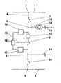
- the single figure shows a simplistic single-phase shown part of a switchgear a Power distribution network.
- FIG. 1 shows a simplified single-phase illustrated Part of a substation, in turn, as part of a not to be considered further represented energy distribution network.
- This switchgear includes, for example, two busbars 1 and 2. From a terminal 3 of the busbar 1 branches one Line 4, which is connected to a terminal 5 of the busbar. 2 connected is. Between the terminal 3 and one likewise with the line 4 connected terminal 6 is a circuit breaker. 7 arranged, which can interrupt the line 4. Between the Terminal 6 and also connected to the line 4 Terminal 8 is a second circuit breaker 9 is arranged, the can interrupt the line 4. Between the terminal 8 and the Terminal 5, a third power switch 10 is arranged, the can interrupt the line 4.
- a connecting line 11 From the terminal 6 branches off a connecting line 11, which the terminal 6 connects to a transformer 12. From Transformer 12 is a line 13. These Connecting line 11 may, depending on the operating state of Power distribution network that serve power supply or she can supply electrical energy via the line 13 to a Disconnect power supply, where energy is needed. Of the Terminal 8 also branches off a line 14, which, depending on Operating state of the power distribution network, electrical Add or remove energy. The power flows through the Line 4 are therefore the respective operating state of Energy distribution network dependent, they can be comparatively quickly change direction.
- a current transformer 15 is provided in the connection between the terminal 6 and the Circuit breaker 9, a current transformer 15 is provided. moreover is in this area connected to terminal 6 Voltage converter 16 connected. In the area between the Terminal 8 and the circuit breaker 9 is another Voltage converter 17 connected.
- the two voltage transformers 16 and 17 are connected to a controller 18, which further processes their measurement signals.
- the ones from Current transformer 15 recorded measurement signals are also in the controller 18 further processed.
- the Control device 18 compares the received measurement signals with already stored data.
- the control device 18 is the power switch 9 assigned.
- the data stored in it include the Characteristics of all possible at this installation site Radiound Error cases and define them clearly. In addition contains they use the algorithm that helps with each specific Druckfall a corresponding network synchronous triggering of Circuit breaker 9 is guaranteed. Further, you can also Data about the current operating status of the Circuit breaker 9, for example, operational Changes to the own time, burn - caused change of the Contact spacing and the like, detected by sensors and considered by the controller 18 accordingly become.
- the circuit breaker 9 is, together with the him associated control device 18, for network-synchronous switching suitable.
- the control device 18 Since here on both sides of the circuit breaker 9 Voltage measurements are provided, the control device 18 also by means of comparisons with the data stored in it always determine clearly in every possible error case which side of the circuit breaker 9 as a reference base for the network-synchronous switching can be used. Especially is also in normal operation, regardless of the Load flow direction through the circuit breaker 9, a mains-synchronous switching of this circuit breaker 9 guaranteed.
- a dashed line of action 19 indicates that the Control device 18, the power switch 9 is actuated when one of the predetermined triggering criteria is met. Of the Circuit breaker 9 is then always triggered so that he switched network synchronously.
- the figure 1 is closer considered.
- the power switch 9 When the power switch 9 is turned off and to be switched on, so deliver the two Voltage transformer 16 and 17 measuring signals, which on the correspond to respective side voltages.
- the Control device 18 When on recognizes the same tension on both sides, recognizes the Control device 18 this and the switching takes place problems. Is however on one side of the circuit breaker 9 no voltage available, d. H. this side of the web is switched off, the controller 18 selects the other Page with voltage applied as reference for the mains-synchronous switching on.
- the circuit breaker 9 then becomes triggered by the controller 18 so that the Contact is made so that little or no Switch-on overvoltages or overcurrents can occur.
- the Mains insulation will not be live in this case significantly loaded, causing the dielectric Operational safety of the network is advantageously improved.
- the Voltage measurement on both sides of the circuit breaker 9 and comparing the readings also prevents two Power supplies operated asynchronously due to a fault be interconnected. Such Failure could cause serious consequential damage. Should capacitive loads are switched on, so will the Circuit breaker 9 so triggered that high inrush currents be avoided.
Landscapes
- Engineering & Computer Science (AREA)
- Power Engineering (AREA)
- Driving Mechanisms And Operating Circuits Of Arc-Extinguishing High-Tension Switches (AREA)
- Remote Monitoring And Control Of Power-Distribution Networks (AREA)
- Keying Circuit Devices (AREA)
- Supply And Distribution Of Alternating Current (AREA)
Priority Applications (6)
| Application Number | Priority Date | Filing Date | Title |
|---|---|---|---|
| DE50201990T DE50201990D1 (de) | 2002-04-05 | 2002-04-05 | Verfahren fur ein netzsynchrones Schalten von Leistungsschaltern und Vorrichtung zur Durchfuhrung dieses Verfahrens |
| AT02405271T ATE287123T1 (de) | 2002-04-05 | 2002-04-05 | Verfahren fur ein netzsynchrones schalten von leistungsschaltern und vorrichtung zur durchfuhrung dieses verfahrens |
| EP20020405271 EP1351267B1 (de) | 2002-04-05 | 2002-04-05 | Verfahren fur ein netzsynchrones Schalten von Leistungsschaltern und Vorrichtung zur Durchfuhrung dieses Verfahrens |
| US10/394,273 US7626286B2 (en) | 2002-04-05 | 2003-03-24 | Method for mains-synchronous switching of circuit breakers, and an apparatus for carrying out this method |
| JP2003097961A JP4381711B2 (ja) | 2002-04-05 | 2003-04-01 | 遮断器を配電系統同期的に開閉する方法及びこの方法を実施する装置 |
| CNB031102093A CN100472685C (zh) | 2002-04-05 | 2003-04-04 | 与电网同步地切换功率开关的方法及执行该方法的装置 |
Applications Claiming Priority (1)
| Application Number | Priority Date | Filing Date | Title |
|---|---|---|---|
| EP20020405271 EP1351267B1 (de) | 2002-04-05 | 2002-04-05 | Verfahren fur ein netzsynchrones Schalten von Leistungsschaltern und Vorrichtung zur Durchfuhrung dieses Verfahrens |
Publications (2)
| Publication Number | Publication Date |
|---|---|
| EP1351267A1 EP1351267A1 (de) | 2003-10-08 |
| EP1351267B1 true EP1351267B1 (de) | 2005-01-12 |
Family
ID=27838211
Family Applications (1)
| Application Number | Title | Priority Date | Filing Date |
|---|---|---|---|
| EP20020405271 Expired - Lifetime EP1351267B1 (de) | 2002-04-05 | 2002-04-05 | Verfahren fur ein netzsynchrones Schalten von Leistungsschaltern und Vorrichtung zur Durchfuhrung dieses Verfahrens |
Country Status (6)
| Country | Link |
|---|---|
| US (1) | US7626286B2 (enExample) |
| EP (1) | EP1351267B1 (enExample) |
| JP (1) | JP4381711B2 (enExample) |
| CN (1) | CN100472685C (enExample) |
| AT (1) | ATE287123T1 (enExample) |
| DE (1) | DE50201990D1 (enExample) |
Families Citing this family (5)
| Publication number | Priority date | Publication date | Assignee | Title |
|---|---|---|---|---|
| DE102005005228A1 (de) * | 2005-01-31 | 2006-08-31 | Siemens Ag | Verfahren sowie Vorrichtung zur Bestimmung eines Schaltzeitpunktes eines elektrischen Schaltgerätes |
| RU2432635C1 (ru) * | 2010-05-28 | 2011-10-27 | Общество с ограниченной ответственностью "АВТ Систем" | Синхронный вакуумный коммутационный аппарат |
| EP2707958B1 (en) | 2011-05-09 | 2015-11-18 | ABB Technology AG | Point-on-wave controller with at least three monitoring inputs |
| KR101592059B1 (ko) * | 2011-06-24 | 2016-02-05 | 엘에스산전 주식회사 | 동기검출 계전기의 제어장치 및 방법 |
| CA3121141C (en) * | 2018-12-27 | 2024-06-04 | Abb Power Grids Switzerland Ag | Method and device for monitoring operation of a switching device for controlled switching applications |
Family Cites Families (5)
| Publication number | Priority date | Publication date | Assignee | Title |
|---|---|---|---|---|
| CH443443A (de) | 1966-04-22 | 1967-09-15 | Bbc Brown Boveri & Cie | Synchronisiereinrichtung an einem Wechselstromleistungsschalter zur Bestimmung des Zeitpunktes, an dem dieser den Ausschaltbefehl erhalten soll |
| JP2892717B2 (ja) * | 1989-11-15 | 1999-05-17 | 株式会社日立製作所 | 電力開閉制御装置 |
| CA2290561A1 (en) * | 1997-05-19 | 1998-11-26 | Uri Rosenschein | Feedback control system for ultrasound probe |
| US6282499B1 (en) * | 1998-12-28 | 2001-08-28 | General Electric Company | Method of detecting manual trips in an intelligent electronic device |
| US6603672B1 (en) * | 2000-11-10 | 2003-08-05 | Ballard Power Systems Corporation | Power converter system |
-
2002
- 2002-04-05 AT AT02405271T patent/ATE287123T1/de active
- 2002-04-05 EP EP20020405271 patent/EP1351267B1/de not_active Expired - Lifetime
- 2002-04-05 DE DE50201990T patent/DE50201990D1/de not_active Expired - Lifetime
-
2003
- 2003-03-24 US US10/394,273 patent/US7626286B2/en not_active Expired - Lifetime
- 2003-04-01 JP JP2003097961A patent/JP4381711B2/ja not_active Expired - Fee Related
- 2003-04-04 CN CNB031102093A patent/CN100472685C/zh not_active Expired - Lifetime
Also Published As
| Publication number | Publication date |
|---|---|
| ATE287123T1 (de) | 2005-01-15 |
| JP2004031322A (ja) | 2004-01-29 |
| CN1450578A (zh) | 2003-10-22 |
| CN100472685C (zh) | 2009-03-25 |
| US20030189378A1 (en) | 2003-10-09 |
| US7626286B2 (en) | 2009-12-01 |
| JP4381711B2 (ja) | 2009-12-09 |
| EP1351267A1 (de) | 2003-10-08 |
| DE50201990D1 (de) | 2005-02-17 |
Similar Documents
| Publication | Publication Date | Title |
|---|---|---|
| DE102020216405B4 (de) | Verfahren zum Ansteuern eines Leistungshalbleiterschalters, Ansteuerschaltung für einen Leistungshalbleiterschalter sowie elektronischer Schutzschalter | |
| EP2296244A1 (de) | Verfahren und Schaltungsanordnung zum Verbinden mindestens eines Strings einer Photovoltaikanlage mit einem Wechselrichter | |
| DE112018005677T5 (de) | Verfahren und vorrichtung zur fehlererkennung und zum schutz von elektrischen netzwerken | |
| WO2001001540A1 (de) | Verfahren zur verhinderung des draufschaltens auf in abzweigen bestehende elektrische kurzschlüsse und zugehörige anordnung | |
| EP3574515B1 (de) | Niederspannungs-schutzschaltgerät | |
| EP0562662A1 (de) | Wechselstrom/Gleichstom-Wandler | |
| EP3510619B1 (de) | Schutzschaltgerät | |
| DE102019101636A1 (de) | Elektrische Schaltungsvorrichtung zur Erkennung eines nichtgeöffneten Schaltkontaktes sowie einer Schutzleiterunterbrechung in einer ein- oder mehrphasigen elektrischen Zuleitung | |
| DE112015000604T5 (de) | System von Stromrichtereinheiten und Stromrichtereinheit | |
| DE102011075353B4 (de) | Fehlerüberwachungssystem für eine Verteilnetzstation eines Energieversorgungsnetzes | |
| EP3361593B1 (de) | Unterbrechungsfreie stromversorgung für lasten | |
| EP1351267B1 (de) | Verfahren fur ein netzsynchrones Schalten von Leistungsschaltern und Vorrichtung zur Durchfuhrung dieses Verfahrens | |
| DE102018128121A1 (de) | AC/DC-Umwandlungs-Anordnung | |
| DE102004034333A1 (de) | Verfahren zum Regeln eines an einer Gleichspannungsquelle angeschlossenen Stromrichters | |
| DE19736903A1 (de) | Umrichter mit Gleichspannungszwischenkreis sowie Verfahren zum Betrieb eines solchen Umrichters | |
| EP2347491B1 (de) | Vorrichtung zur speisung eines abnehmernetzes mit der elektrischen leistung eines versorgungsnetzes | |
| EP2345130B1 (de) | Vorrichtung zur speisung eines abnehmernetzes mit der elektrischen leistung eines versorgungsnetzes | |
| EP3278349B1 (de) | Schaltschrankanordnung mit verbesserter ausschaltung bei überlast | |
| EP2070172A1 (de) | Redundantes schutzsystem und verfahren zum redundanten überwachen von schutzobjekten in einem elektrischen energieversorgungsnetz | |
| EP1110797B1 (de) | Einrichtung und Verfahren zum Stromrichter-Überlastschutz | |
| DE202016104781U1 (de) | Schaltungsanordnung zum Schutz von an einem mehrphasigen Netz angeschlossenen Verbrauchern mit Unter- und Überspannungsabschaltfunktion | |
| EP1808946B1 (de) | Verfahren zur Überwachung eines abschaltbaren Kabels in einem elektrischen Netz, dafür geeignete Überwachungsvorrichtung sowie Überwachungssystem | |
| DE102022201962B3 (de) | Verfahren zum Betreiben eines elektronischen Schutzschalters, elektronischer Schutzschalter sowie elektrische Anlage mit einem elektronischen Schutzschalter | |
| DE2309688A1 (de) | Schaltungsanordnung zum automatischen ein- bzw. ausschalten der betriebsspannung | |
| DE10050896B4 (de) | Verfahren und Vorrichtung zur Blindleistungskompensation |
Legal Events
| Date | Code | Title | Description |
|---|---|---|---|
| PUAI | Public reference made under article 153(3) epc to a published international application that has entered the european phase |
Free format text: ORIGINAL CODE: 0009012 |
|
| AK | Designated contracting states |
Kind code of ref document: A1 Designated state(s): AT BE CH CY DE DK ES FI FR GB GR IE IT LI LU MC NL PT SE TR |
|
| AX | Request for extension of the european patent |
Extension state: AL LT LV MK RO SI |
|
| 17P | Request for examination filed |
Effective date: 20040318 |
|
| AKX | Designation fees paid |
Designated state(s): AT BE CH CY DE DK ES FI FR GB GR IE IT LI LU MC NL PT SE TR |
|
| GRAP | Despatch of communication of intention to grant a patent |
Free format text: ORIGINAL CODE: EPIDOSNIGR1 |
|
| GRAS | Grant fee paid |
Free format text: ORIGINAL CODE: EPIDOSNIGR3 |
|
| GRAA | (expected) grant |
Free format text: ORIGINAL CODE: 0009210 |
|
| AK | Designated contracting states |
Kind code of ref document: B1 Designated state(s): AT BE CH CY DE DK ES FI FR GB GR IE IT LI LU MC NL PT SE TR |
|
| PG25 | Lapsed in a contracting state [announced via postgrant information from national office to epo] |
Ref country code: GB Free format text: LAPSE BECAUSE OF FAILURE TO SUBMIT A TRANSLATION OF THE DESCRIPTION OR TO PAY THE FEE WITHIN THE PRESCRIBED TIME-LIMIT Effective date: 20050112 Ref country code: IT Free format text: LAPSE BECAUSE OF FAILURE TO SUBMIT A TRANSLATION OF THE DESCRIPTION OR TO PAY THE FEE WITHIN THE PRESCRIBED TIME-LIMIT;WARNING: LAPSES OF ITALIAN PATENTS WITH EFFECTIVE DATE BEFORE 2007 MAY HAVE OCCURRED AT ANY TIME BEFORE 2007. THE CORRECT EFFECTIVE DATE MAY BE DIFFERENT FROM THE ONE RECORDED. Effective date: 20050112 Ref country code: NL Free format text: LAPSE BECAUSE OF FAILURE TO SUBMIT A TRANSLATION OF THE DESCRIPTION OR TO PAY THE FEE WITHIN THE PRESCRIBED TIME-LIMIT Effective date: 20050112 Ref country code: TR Free format text: LAPSE BECAUSE OF FAILURE TO SUBMIT A TRANSLATION OF THE DESCRIPTION OR TO PAY THE FEE WITHIN THE PRESCRIBED TIME-LIMIT Effective date: 20050112 Ref country code: IE Free format text: LAPSE BECAUSE OF FAILURE TO SUBMIT A TRANSLATION OF THE DESCRIPTION OR TO PAY THE FEE WITHIN THE PRESCRIBED TIME-LIMIT Effective date: 20050112 Ref country code: FI Free format text: LAPSE BECAUSE OF FAILURE TO SUBMIT A TRANSLATION OF THE DESCRIPTION OR TO PAY THE FEE WITHIN THE PRESCRIBED TIME-LIMIT Effective date: 20050112 |
|
| REG | Reference to a national code |
Ref country code: GB Ref legal event code: FG4D Free format text: NOT ENGLISH |
|
| REG | Reference to a national code |
Ref country code: CH Ref legal event code: EP |
|
| REF | Corresponds to: |
Ref document number: 50201990 Country of ref document: DE Date of ref document: 20050217 Kind code of ref document: P |
|
| REG | Reference to a national code |
Ref country code: IE Ref legal event code: FG4D Free format text: GERMAN |
|
| PG25 | Lapsed in a contracting state [announced via postgrant information from national office to epo] |
Ref country code: LU Free format text: LAPSE BECAUSE OF NON-PAYMENT OF DUE FEES Effective date: 20050405 Ref country code: CY Free format text: LAPSE BECAUSE OF FAILURE TO SUBMIT A TRANSLATION OF THE DESCRIPTION OR TO PAY THE FEE WITHIN THE PRESCRIBED TIME-LIMIT Effective date: 20050405 |
|
| PG25 | Lapsed in a contracting state [announced via postgrant information from national office to epo] |
Ref country code: SE Free format text: LAPSE BECAUSE OF FAILURE TO SUBMIT A TRANSLATION OF THE DESCRIPTION OR TO PAY THE FEE WITHIN THE PRESCRIBED TIME-LIMIT Effective date: 20050412 Ref country code: DK Free format text: LAPSE BECAUSE OF FAILURE TO SUBMIT A TRANSLATION OF THE DESCRIPTION OR TO PAY THE FEE WITHIN THE PRESCRIBED TIME-LIMIT Effective date: 20050412 |
|
| PG25 | Lapsed in a contracting state [announced via postgrant information from national office to epo] |
Ref country code: ES Free format text: LAPSE BECAUSE OF FAILURE TO SUBMIT A TRANSLATION OF THE DESCRIPTION OR TO PAY THE FEE WITHIN THE PRESCRIBED TIME-LIMIT Effective date: 20050423 |
|
| PG25 | Lapsed in a contracting state [announced via postgrant information from national office to epo] |
Ref country code: MC Free format text: LAPSE BECAUSE OF NON-PAYMENT OF DUE FEES Effective date: 20050430 Ref country code: BE Free format text: LAPSE BECAUSE OF NON-PAYMENT OF DUE FEES Effective date: 20050430 |
|
| NLV1 | Nl: lapsed or annulled due to failure to fulfill the requirements of art. 29p and 29m of the patents act | ||
| GBV | Gb: ep patent (uk) treated as always having been void in accordance with gb section 77(7)/1977 [no translation filed] |
Effective date: 20050112 |
|
| REG | Reference to a national code |
Ref country code: IE Ref legal event code: FD4D |
|
| BERE | Be: lapsed |
Owner name: ABB TECHNOLOGY A.G. Effective date: 20050430 |
|
| PLBE | No opposition filed within time limit |
Free format text: ORIGINAL CODE: 0009261 |
|
| STAA | Information on the status of an ep patent application or granted ep patent |
Free format text: STATUS: NO OPPOSITION FILED WITHIN TIME LIMIT |
|
| ET | Fr: translation filed | ||
| 26N | No opposition filed |
Effective date: 20051013 |
|
| PG25 | Lapsed in a contracting state [announced via postgrant information from national office to epo] |
Ref country code: LI Free format text: LAPSE BECAUSE OF NON-PAYMENT OF DUE FEES Effective date: 20060430 Ref country code: CH Free format text: LAPSE BECAUSE OF NON-PAYMENT OF DUE FEES Effective date: 20060430 |
|
| REG | Reference to a national code |
Ref country code: CH Ref legal event code: PL |
|
| BERE | Be: lapsed |
Owner name: ABB TECHNOLOGY A.G. Effective date: 20050430 |
|
| PG25 | Lapsed in a contracting state [announced via postgrant information from national office to epo] |
Ref country code: PT Free format text: LAPSE BECAUSE OF NON-PAYMENT OF DUE FEES Effective date: 20050612 |
|
| PG25 | Lapsed in a contracting state [announced via postgrant information from national office to epo] |
Ref country code: GR Free format text: LAPSE BECAUSE OF NON-PAYMENT OF DUE FEES Effective date: 20050112 |
|
| PGFP | Annual fee paid to national office [announced via postgrant information from national office to epo] |
Ref country code: AT Payment date: 20120411 Year of fee payment: 11 |
|
| REG | Reference to a national code |
Ref country code: AT Ref legal event code: MM01 Ref document number: 287123 Country of ref document: AT Kind code of ref document: T Effective date: 20140405 |
|
| PG25 | Lapsed in a contracting state [announced via postgrant information from national office to epo] |
Ref country code: AT Free format text: LAPSE BECAUSE OF NON-PAYMENT OF DUE FEES Effective date: 20140405 |
|
| REG | Reference to a national code |
Ref country code: FR Ref legal event code: PLFP Year of fee payment: 15 |
|
| REG | Reference to a national code |
Ref country code: DE Ref legal event code: R081 Ref document number: 50201990 Country of ref document: DE Owner name: ABB SCHWEIZ AG, CH Free format text: FORMER OWNER: ABB TECHNOLOGY AG, ZUERICH, CH Ref country code: DE Ref legal event code: R081 Ref document number: 50201990 Country of ref document: DE Owner name: ABB POWER GRIDS SWITZERLAND AG, CH Free format text: FORMER OWNER: ABB TECHNOLOGY AG, ZUERICH, CH Ref country code: DE Ref legal event code: R082 Ref document number: 50201990 Country of ref document: DE Representative=s name: DENNEMEYER & ASSOCIATES S.A., DE Ref country code: DE Ref legal event code: R082 Ref document number: 50201990 Country of ref document: DE Representative=s name: ZIMMERMANN & PARTNER PATENTANWAELTE MBB, DE |
|
| REG | Reference to a national code |
Ref country code: FR Ref legal event code: PLFP Year of fee payment: 16 |
|
| REG | Reference to a national code |
Ref country code: FR Ref legal event code: PLFP Year of fee payment: 17 |
|
| REG | Reference to a national code |
Ref country code: FR Ref legal event code: TP Owner name: ABB SCHWEIZ AG, CH Effective date: 20180912 |
|
| REG | Reference to a national code |
Ref country code: DE Ref legal event code: R082 Ref document number: 50201990 Country of ref document: DE Representative=s name: DENNEMEYER & ASSOCIATES S.A., DE Ref country code: DE Ref legal event code: R081 Ref document number: 50201990 Country of ref document: DE Owner name: ABB POWER GRIDS SWITZERLAND AG, CH Free format text: FORMER OWNER: ABB SCHWEIZ AG, BADEN, CH |
|
| PGFP | Annual fee paid to national office [announced via postgrant information from national office to epo] |
Ref country code: DE Payment date: 20210420 Year of fee payment: 20 Ref country code: FR Payment date: 20210423 Year of fee payment: 20 |
|
| REG | Reference to a national code |
Ref country code: DE Ref legal event code: R071 Ref document number: 50201990 Country of ref document: DE |