EP1351084A1 - Optical fibre cable and manufacturing method - Google Patents
Optical fibre cable and manufacturing method Download PDFInfo
- Publication number
- EP1351084A1 EP1351084A1 EP03290718A EP03290718A EP1351084A1 EP 1351084 A1 EP1351084 A1 EP 1351084A1 EP 03290718 A EP03290718 A EP 03290718A EP 03290718 A EP03290718 A EP 03290718A EP 1351084 A1 EP1351084 A1 EP 1351084A1
- Authority
- EP
- European Patent Office
- Prior art keywords
- cable
- frame
- optical
- edges
- optical fibers
- Prior art date
- Legal status (The legal status is an assumption and is not a legal conclusion. Google has not performed a legal analysis and makes no representation as to the accuracy of the status listed.)
- Withdrawn
Links
- 239000013307 optical fiber Substances 0.000 title claims abstract description 41
- 238000004519 manufacturing process Methods 0.000 title claims abstract description 9
- 230000003287 optical effect Effects 0.000 claims abstract description 37
- 230000002787 reinforcement Effects 0.000 claims abstract description 16
- 239000000835 fiber Substances 0.000 claims description 15
- 229920002994 synthetic fiber Polymers 0.000 claims description 13
- 239000000463 material Substances 0.000 claims description 12
- 229920002430 Fibre-reinforced plastic Polymers 0.000 claims description 8
- 239000011151 fibre-reinforced plastic Substances 0.000 claims description 8
- 239000011152 fibreglass Substances 0.000 claims description 8
- 238000000034 method Methods 0.000 claims description 6
- 229910000831 Steel Inorganic materials 0.000 claims description 4
- 239000003365 glass fiber Substances 0.000 claims description 4
- 239000002184 metal Substances 0.000 claims description 4
- 239000010959 steel Substances 0.000 claims description 4
- 239000000843 powder Substances 0.000 claims description 3
- 239000012815 thermoplastic material Substances 0.000 claims description 2
- 238000001125 extrusion Methods 0.000 description 5
- 230000008602 contraction Effects 0.000 description 4
- 239000000969 carrier Substances 0.000 description 3
- 238000005520 cutting process Methods 0.000 description 3
- 229920000092 linear low density polyethylene Polymers 0.000 description 3
- 239000004707 linear low-density polyethylene Substances 0.000 description 3
- 230000003014 reinforcing effect Effects 0.000 description 3
- 229920001903 high density polyethylene Polymers 0.000 description 2
- 239000004700 high-density polyethylene Substances 0.000 description 2
- 238000009434 installation Methods 0.000 description 2
- 239000004698 Polyethylene Substances 0.000 description 1
- 241001639412 Verres Species 0.000 description 1
- 239000004760 aramid Substances 0.000 description 1
- 229920003235 aromatic polyamide Polymers 0.000 description 1
- 238000005452 bending Methods 0.000 description 1
- 239000011521 glass Substances 0.000 description 1
- 239000003292 glue Substances 0.000 description 1
- 229920001778 nylon Polymers 0.000 description 1
- 229920000728 polyester Polymers 0.000 description 1
- -1 polyethylene Polymers 0.000 description 1
- 229920000573 polyethylene Polymers 0.000 description 1
- 238000005096 rolling process Methods 0.000 description 1
- 238000007789 sealing Methods 0.000 description 1
- 229910000679 solder Inorganic materials 0.000 description 1
- 229920001169 thermoplastic Polymers 0.000 description 1
- 239000004416 thermosoftening plastic Substances 0.000 description 1
Images

Classifications
-
- G—PHYSICS
- G02—OPTICS
- G02B—OPTICAL ELEMENTS, SYSTEMS OR APPARATUS
- G02B6/00—Light guides; Structural details of arrangements comprising light guides and other optical elements, e.g. couplings
- G02B6/44—Mechanical structures for providing tensile strength and external protection for fibres, e.g. optical transmission cables
- G02B6/4401—Optical cables
- G02B6/4429—Means specially adapted for strengthening or protecting the cables
- G02B6/443—Protective covering
- G02B6/4431—Protective covering with provision in the protective covering, e.g. weak line, for gaining access to one or more fibres, e.g. for branching or tapping
Definitions
- the present invention relates to a fiber optic cable and a method of manufacture of this cable.
- Fiber optic cables hereinafter called optical cables, are susceptible to present structures of different types.
- a fiber optic cable of the type comprising a sheath, in which are housed optical fibers, and a substantially annular reinforcing reinforcement, interposed radially between the optical fibers and the sheath.
- the optical cable described in US-A-6 091 871 is of the type usually called "Uni-tube".
- This type of optical cable has a relatively small number of fibers optics.
- the optical fibers are housed in a single tube coated with the sheath.
- of the filiform elements forming traction reinforcements, usually called carriers, are embedded in a wall defining the sheath. The presence of carriers limits the possibilities of reduce the diameter of the sheath.
- the object of the invention is to propose an optical cable comprising a number relatively weak optical fibers (e.g. a dozen optical fibers) having as small a diameter as possible, usually keeping the characteristics desired for this type of cable, i.e. good resistance to crushing and traction and weak cold contraction.
- a number relatively weak optical fibers e.g. a dozen optical fibers
- the subject of the invention is a fiber optic cable of the aforementioned type, characterized in that the armature comprises a slot extending in the general longitudinal direction of the armature, this slot being delimited by edges of the frame separated or joined and allowing access to the optical fibers housed in the frame.
- the filling material prior to the extrusion of the sheath, the filling material is placed in the frame.
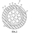
- FIG. 1 shows a fiber optic cable according to a first mode for carrying out the invention, designated by the general reference 10.
- the optical cable 10 comprises a bundle of conventional optical fibers 12. This bundle is housed in a substantially annular reinforcement frame 14. All reinforcement 14 - optical fibers 12 will hereinafter be called optical assembly 16.
- the optical assembly 16 is coated with a sheath 18.
- the frame 14 is therefore interposed radially between the optical fibers 12 and the sheath 18.
- the armature 14 is the only armature of the cable 10.
- the optical cable 10 comprises a relatively limited number of optical fibers 12, for example a dozen.
- the frame 14 is made of synthetic material reinforced, where appropriate, with fibers, in particular glass fibers, so as to limit the contraction of the optical cable 10 when cold.
- This synthetic material can in particular be of the type designated by the Anglo-Saxon acronym FRP (Fiber Reinforced Plastic) or GRP (Glass-fiber Reinforced Plastic).
- FRP Fiber Reinforced Plastic
- GRP Glass-fiber Reinforced Plastic
- the synthetic material can also be a material thermoplastic reinforced with glass fibers, especially in the form of wicks.
- the frame 14 can be made of metal, in particular steel, by example by rolling a steel sheet.
- the sheath 18 is made of a conventional synthetic material.
- This material classic is for example linear low density polyethylene usually designated by the Anglo-Saxon acronym LLDPE (Linear Low Density Polyethylene) or polyethylene to high density usually designated by the Anglo-Saxon acronym HDPE (High Density Polyethylene).
- LLDPE Linear Low Density Polyethylene
- HDPE High Density Polyethylene
- the armature 14 comprises a slot 20 extending in the direction longitudinal general of the frame 14. This slot 20 allows easy access to the fibers optics 12 housed in the frame 14.
- the slot 20 is delimited by edges B1, B2 of the frame 14 spaced a relatively small distance but greater than the diameter of an optical fiber 12.
- edges B1, B2 of the frame 14 delimiting the slot 20 are rectilinear.
- the edges B1, B2 of the frame 14 delimiting the slot 20 could extend along a path moving longitudinally in SZ.
- a filling material 22 is housed in the frame 14.
- This material in particular in the form of a gel or a powder, participates the sealing of the optical cable 10 and the protection of the optical fibers 12 during the extrusion of the sheath 18.
- the procedure is preferably as follows.
- the armature 14 is manufactured for example by extrusion if this frame 14 is made of synthetic material or else by bending a sheet metal if this frame 14 is metallic.
- the optical fibers 12 are housed in the frame 14 so as to form the optical assembly 16.
- the optical fibers 12 are introduced into the frame 14 through the slot 20.
- the filling material 22 is introduced into the reinforcement 14 before the extrusion of the sheath 18.
- the introduction of the filling material 22 in the frame 14 is done concomitantly with the introduction of the optical fibers 12 in this frame 14.
- the manufacture of the optical assembly 16 can be carried out in a installation separate from the installation in which the sheath 18 is extruded around the optical assembly 16. This authorizes the subcontracting of the manufacture of the optical assembly 16.
- the frame 14 gives the optical cable 10 good resistance to crushing and tensile and guarantees a low cold contraction of this optical cable 10.
- the step of extruding the sheath 18 around the optical assembly 16 can be carried out quickly and the thickness of the sheath 18 can be limited, which reduces correspondingly the external diameter of the optical cable 10.
- the frame 14 comprises two longitudinal half-frames 14A, 14B.
- Each half-frame 14A, 14B is provided with edges B1, B2 of contact with each other half-frame 14B, 14A.
- the contact edges B1, B2 of the two half-frames 14A, 14B form contiguous edges delimiting two slots 20 for access to the optical fibers 12.
- the edges B1, B2 of the frame 14 delimiting the two slots 20 are preferably rectilinear.
- the two half-frames 14A, 14B are held against each other using tearable or breakable means.
- These means include, for example, a link 24 wrapped around the frame 14 (covering).
- the link 24 can be threadlike or have a general form of ribbon.
- the link 24 is made for example from a material such as polyester, nylon ® or aramid.
- the user accesses the optical fibers 12 by cutting the sheath 18 at the right of the slot 20.
- the optical fibers 12 can be easily extracted from the armature 14 to through this slot 20.
- the user accesses the optical fibers 12 by cutting the sheath 18 and by cutting or by tearing the link 24 holding the two half-frames 14A, 14B against each other.
- the two half-frames 14A, 14B can then be separated from one another so as to open one of the slots 20 and give access to the optical fibers 12 housed in the frame 14.
- the invention therefore makes it possible to propose an optical cable, comprising a number relatively small optical fibers, having a reduced diameter, this preserving thanks to the reinforcing reinforcement 14 the characteristics usually desired for this type of cable, i.e. good crushing and tensile strength and low cold contraction.
- optical cable 10 consists of a number limited components and materials.
- the invention allows easy access to the optical fibers 12 of the cable. optical 10, even in the middle of the cable by incising the sheath 18.
- the optical fibers 12 can thus be connected by stitching the optical cable 10.
- the slot 20 is free, that is to say not blocked. Indeed, the slot 20 is not clogged with glue or solder.
Abstract
Description
La présente invention concerne un câble à fibres optiques et un procédé de fabrication de ce câble.The present invention relates to a fiber optic cable and a method of manufacture of this cable.
Les câbles à fibres optiques, appelés par la suite câbles optiques, sont susceptibles de présenter des structures de différents types.Fiber optic cables, hereinafter called optical cables, are susceptible to present structures of different types.
On connaít déjà dans l'état de la technique, notamment d'après US-A-6 091 871, un câble à fibres optiques du type comprenant une gaine, dans laquelle sont logées des fibres optiques, et une armature de renfort sensiblement annulaire, intercalée radialement entre les fibres optiques et la gaine.We already know in the prior art, especially from US-A-6,091 871, a fiber optic cable of the type comprising a sheath, in which are housed optical fibers, and a substantially annular reinforcing reinforcement, interposed radially between the optical fibers and the sheath.
Le câble optique décrit dans US-A-6 091 871 est du type appelé habituellement « uni-tube ». Ce type de câble optique comprend un nombre relativement faible de fibres optiques. Les fibres optiques sont logées dans un tube unique revêtu de la gaine. Des éléments filiformes formant renforts de traction, appelés habituellement porteurs, sont noyés dans une paroi délimitant la gaine. La présence des porteurs limite les possibilités de réduire le diamètre de la gaine.The optical cable described in US-A-6 091 871 is of the type usually called "Uni-tube". This type of optical cable has a relatively small number of fibers optics. The optical fibers are housed in a single tube coated with the sheath. of the filiform elements forming traction reinforcements, usually called carriers, are embedded in a wall defining the sheath. The presence of carriers limits the possibilities of reduce the diameter of the sheath.
L'invention a pour but de proposer un câble optique comprenant un nombre relativement faible de fibres optiques (par exemple une douzaine de fibres optiques) ayant un diamètre aussi petit que possible, ceci en conservant les caractéristiques habituellement souhaitées pour ce type de câble, à savoir une bonne résistance à l'écrasement et à la traction et une faible contraction à froid.The object of the invention is to propose an optical cable comprising a number relatively weak optical fibers (e.g. a dozen optical fibers) having as small a diameter as possible, usually keeping the characteristics desired for this type of cable, i.e. good resistance to crushing and traction and weak cold contraction.
A cet effet, l'invention a pour objet un câble à fibres optiques du type précité, caractérisé en ce que l'armature comprend une fente s'étendant dans la direction générale longitudinale de l'armature, cette fente étant délimitée par des bords de l'armature écartés ou jointifs et permettant un accès aux fibres optiques logées dans l'armature.To this end, the subject of the invention is a fiber optic cable of the aforementioned type, characterized in that the armature comprises a slot extending in the general longitudinal direction of the armature, this slot being delimited by edges of the frame separated or joined and allowing access to the optical fibers housed in the frame.
Suivant des caractéristiques de différents modes de réalisation de ce câble optique :
- les bords de l'armature délimitant la fente d'accès sont écartés d'une distance supérieure au diamètre d'une fibre optique ;
- l'armature comprend deux demi-armatures longitudinales, chaque demi-armature étant munie de bords de contact avec l'autre demi-armature, les bords de contact des deux demi-armatures formant des bords jointifs délimitant deux fentes d'accès aux fibres optiques ;
- le câble optique comprend des moyens déchirables ou sécables de maintien des deux demi-armatures l'une contre l'autre ;
- les moyens de maintien des demi-armatures comprennent un lien enroulé autour de l'armature ;
- l'armature est en matériau synthétique ;
- le matériau synthétique de l'armature est renforcé avec des fibres, notamment des fibres de verre, ce matériau synthétique étant notamment du type désigné par le sigle anglo-saxon FRP (Fiber Reinforced Plastic) ou GRP (Glass-fiber Reinforced Plastic) ;
- le matériau synthétique de l'armature est un matériau thermoplastique ;
- l'armature est en métal, notamment en acier ;
- les bords de l'armature délimitant la fente d'accès sont rectilignes ;
- les bords de l'armature délimitant la fente d'accès s'étendent suivant un trajet évoluant longitudinalement en SZ ;
- un matériau de remplissage, notamment sous la forme d'un gel ou d'une poudre, est logé dans l'armature.
- the edges of the frame delimiting the access slot are spaced apart by a distance greater than the diameter of an optical fiber;
- the frame comprises two longitudinal half-frames, each half-frame being provided with contact edges with the other half-frame, the contact edges of the two half-frames forming contiguous edges delimiting two slots for access to the optical fibers ;
- the optical cable comprises tearable or breakable means for holding the two half-frames against each other;
- the means for holding the half-frames comprise a link wound around the frame;
- the frame is made of synthetic material;
- the synthetic material of the frame is reinforced with fibers, in particular glass fibers, this synthetic material being in particular of the type designated by the acronym FRP (Fiber Reinforced Plastic) or GRP (Glass-fiber Reinforced Plastic);
- the synthetic material of the frame is a thermoplastic material;
- the frame is made of metal, in particular steel;
- the edges of the frame delimiting the access slot are rectilinear;
- the edges of the frame delimiting the access slot extend along a path evolving longitudinally in SZ;
- a filling material, in particular in the form of a gel or a powder, is housed in the frame.
L'invention a également pour objet un procédé de fabrication d'un câble optique tel que défini ci-dessus, caractérisé en ce que :
- on fabrique l'armature,
- on loge les fibres optiques dans l'armature de façon à former un ensemble armature-fibres optiques appelé ensemble optique, et
- on extrude la gaine autour de l'ensemble optique.
- we make the frame,
- the optical fibers are housed in the armature so as to form an armature-optical fiber assembly called the optical assembly, and
- the sheath is extruded around the optical assembly.
Suivant une autre caractéristique de ce procédé, préalablement à l'extrusion de la gaine, on place dans l'armature le matériau de remplissage.According to another characteristic of this process, prior to the extrusion of the sheath, the filling material is placed in the frame.
L'invention sera mieux comprise à la lecture de la description qui va suivre, donnée uniquement à titre d'exemple et faite en se référant aux dessins annexés dans lesquels :
- la figure 1 est une vue en coupe transversale d'un câble à fibres optiques selon un premier mode de réalisation de l'invention ;
- la figure 2 est une vue similaire à la figure 1 d'un câble à fibres optiques selon un second mode de réalisation de l'invention ;
- la figure 3 est une vue de côté du câble optique représenté sur la figure 2.
- Figure 1 is a cross-sectional view of a fiber optic cable according to a first embodiment of the invention;
- Figure 2 is a view similar to Figure 1 of a fiber optic cable according to a second embodiment of the invention;
- FIG. 3 is a side view of the optical cable shown in FIG. 2.
On a représenté sur la figure 1 un câble à fibres optiques selon un premier mode
de réalisation de l'invention, désigné par la référence générale 10.FIG. 1 shows a fiber optic cable according to a first mode
for carrying out the invention, designated by the
Le câble optique 10 comprend un faisceau de fibres optiques classiques 12. Ce
faisceau est logé dans une armature de renfort 14 sensiblement annulaire. L'ensemble
armature 14 - fibres optiques 12 sera appelé par la suite ensemble optique 16. The
L'ensemble optique 16 est revêtu d'une gaine 18. L'armature 14 est donc intercalée
radialement entre les fibres optiques 12 et la gaine 18.The
De préférence, l'armature 14 est la seule armature du câble 10.Preferably, the
Le câble optique 10 comprend un nombre relativement limité de fibres optiques 12,
par exemple une douzaine.The
Dans l'exemple illustré sur les figures, l'armature 14 est en matériau synthétique
renforcé, le cas échéant, avec des fibres, notamment des fibres de verre, de façon à limiter
la contraction du câble optique 10 à froid. Ce matériau synthétique peut être notamment
du type désigné par le sigle anglo-saxon FRP (Fiber Reinforced Plastic) ou GRP (Glass-fiber
Reinforced Plastic). Le matériau synthétique peut également être un matériau
thermoplastique renforcé avec des fibres de verre notamment sous forme de mèches.In the example illustrated in the figures, the
En variante, l'armature 14 peut être réalisée en métal, notamment en acier, par
exemple en roulant une tôle en acier.As a variant, the
La gaine 18 est fabriquée dans un matériau synthétique classique. Ce matériau
classique est par exemple du polyéthylène linéaire à basse densité désigné habituellement
par le sigle anglo-saxon LLDPE (Linear Low Density Polyethylene) ou bien du polyéthylène à
haute densité désigné habituellement par le sigle anglo-saxon HDPE (High Density
Polyethylene).The
Selon l'invention, l'armature 14 comprend une fente 20 s'étendant dans la direction
générale longitudinale de l'armature 14. Cette fente 20 permet un accès aisé aux fibres
optiques 12 logées dans l'armature 14.According to the invention, the
Dans le premier mode de réalisation de l'invention, la fente 20 est délimitée par
des bords B1, B2 de l'armature 14 écartés d'une distance relativement faible mais
supérieure au diamètre d'une fibre optique 12.In the first embodiment of the invention, the
On notera également que, dans le premier mode de réalisation de l'invention, les
bords B1, B2 de l'armature 14 délimitant la fente 20 sont rectilignes. En variante, les bords
B1, B2 de l'armature 14 délimitant la fente 20 pourraient s'étendre suivant un trajet
évoluant longitudinalement en SZ.It will also be noted that, in the first embodiment of the invention, the
edges B1, B2 of the
De préférence, un matériau de remplissage 22, de type classique, est logé dans
l'armature 14. Ce matériau, notamment sous la forme d'un gel ou d'une poudre, participe
à l'étanchéité du câble optique 10 et à la protection des fibres optiques 12 lors de
l'extrusion de la gaine 18.Preferably, a filling
Pour fabriquer le câble optique 10, on procède de préférence de la façon suivante. To manufacture the
Tout d'abord, on fabrique l'armature 14 par exemple par extrusion si cette
armature 14 est en matériau synthétique ou bien par pliage d'une tôle si cette armature 14
est métallique.First of all, the
Puis, préalablement à l'extrusion de la gaine 18, on loge les fibres optiques 12
dans l'armature 14 de façon à former l'ensemble optique 16. Les fibres optiques 12 sont
introduites dans l'armature 14 à travers la fente 20.Then, prior to the extrusion of the
Le matériau de remplissage 22 est introduit dans l'armature 14 préalablement à
l'extrusion de la gaine 18. De préférence, l'introduction du matériau de remplissage 22
dans l'armature 14 se fait de façon concomitante avec l'introduction des fibres optiques 12
dans cette armature 14.The filling
Le cas échéant, la fabrication de l'ensemble optique 16 peut être réalisée dans une
installation distincte de l'installation dans laquelle est réalisée l'extrusion de la gaine 18
autour de l'ensemble optique 16. Ceci autorise la sous-traitance de la fabrication de
l'ensemble optique 16.Where appropriate, the manufacture of the
L'armature 14 confère au câble optique 10 une bonne résistance à l'écrasement et
à la traction et garantit une faible contraction à froid de ce câble optique 10.The
Par conséquent, il n'est pas nécessaire, pour obtenir les caractéristiques ci-dessus,
de loger dans la gaine 18 des éléments de renfort tels que des porteurs ou des fibres de
verre.Therefore, it is not necessary, to obtain the above characteristics,
to house in the
De ce fait, l'étape d'extrusion de la gaine 18 autour de l'ensemble optique 16 peut
être réalisée rapidement et l'épaisseur de la gaine 18 peut être limitée ce qui réduit
d'autant le diamètre externe du câble optique 10.Therefore, the step of extruding the
Sur les figures 2 et 3, on a représenté un câble optique 10 selon un second mode
de réalisation de l'invention. Sur ces figures, les éléments analogues à ceux des figures
précédentes sont désignés par des références identiques.In Figures 2 and 3, there is shown an
Dans ce cas, l'armature 14 comprend deux demi-armatures longitudinales 14A,
14B. Chaque demi-armature 14A, 14B est munie de bords B1, B2 de contact avec l'autre
demi-armature 14B, 14A. Les bords de contact B1, B2 des deux demi-armatures 14A, 14B
forment des bords jointifs délimitant deux fentes 20 d'accès aux fibres optiques 12. Les
bords B1, B2 de l'armature 14 délimitant les deux fentes 20 sont de préférence rectilignes.In this case, the
Les deux demi-armatures 14A, 14B sont maintenues l'une contre l'autre à l'aide de
moyens déchirables ou sécables. Ces moyens comprennent par exemple un lien 24
enroulé autour de l'armature 14 (guipage). Le lien 24 peut être filiforme ou avoir une
forme générale de ruban. Le lien 24 est fabriqué par exemple dans un matériau tel que le
polyester, le nylon ® ou l'aramide. The two half-
Parmi les avantages de l'invention, on notera que celle-ci permet un accès facile au
fibres optiques 12 du câble optique 10 et ainsi un raccordement aisé de ces fibres optiques
12.Among the advantages of the invention, it will be noted that it allows easy access to the
En effet, dans le câble optique 10 selon le premier mode de réalisation de
l'invention, l'utilisateur accède aux fibres optiques 12 en découpant la gaine 18 au droit de
la fente 20. Les fibres optiques 12 peuvent être extraites facilement de l'armature 14 à
travers cette fente 20.Indeed, in the
Dans le câble optique 10 selon le second mode de réalisation de l'invention,
l'utilisateur accède aux fibres optiques 12 en découpant la gaine 18 et en sectionnant ou
en déchirant le lien 24 maintenant les deux demi-armatures 14A, 14B l'une contre l'autre.
Les deux demi-armatures 14A, 14B peuvent alors être écartées l'une de l'autre de façon à
ouvrir une des fentes 20 et à donner accès aux fibres optiques 12 logées dans l'armature
14.In the
L'invention permet donc de proposer un câble optique, comprenant un nombre
relativement faible de fibres optiques, ayant un diamètre réduit, ceci en conservant grâce à
l'armature de renfort 14 les caractéristiques habituellement souhaitées pour ce type de
câble, à savoir une bonne résistance à l'écrasement et à la traction et une faible
contraction à froid.The invention therefore makes it possible to propose an optical cable, comprising a number
relatively small optical fibers, having a reduced diameter, this preserving thanks to
the reinforcing
On notera que le câble optique 10 selon l'invention est constitué d'un nombre
limité de composants et de matériaux.It will be noted that the
Par ailleurs, l'invention permet d'accéder facilement aux fibres optiques 12 du câble
optique 10, même en milieu de câble par incision de la gaine 18. Les fibres optiques 12
peuvent ainsi être raccordées par piquage du câble optique 10.Furthermore, the invention allows easy access to the
Une fois l'armature 14 mise à nue, au moins partiellement, l'accès aux fibres 12 se
fait sans outil par passage à travers la fente 20.Once the
La fente 20 est libre, c'est-à-dire non bouchée. En effet, la fente 20 n'est pas
bouchée par une colle ou par une soudure.The
Claims (14)
Applications Claiming Priority (2)
| Application Number | Priority Date | Filing Date | Title |
|---|---|---|---|
| FR0204085A FR2837932B1 (en) | 2002-04-02 | 2002-04-02 | OPTICAL FIBER CABLE AND METHOD FOR MANUFACTURING THE SAME |
| FR0204085 | 2002-04-02 |
Publications (1)
| Publication Number | Publication Date |
|---|---|
| EP1351084A1 true EP1351084A1 (en) | 2003-10-08 |
Family
ID=27839390
Family Applications (1)
| Application Number | Title | Priority Date | Filing Date |
|---|---|---|---|
| EP03290718A Withdrawn EP1351084A1 (en) | 2002-04-02 | 2003-03-21 | Optical fibre cable and manufacturing method |
Country Status (4)
| Country | Link |
|---|---|
| US (1) | US20030185528A1 (en) |
| EP (1) | EP1351084A1 (en) |
| CN (1) | CN1450376A (en) |
| FR (1) | FR2837932B1 (en) |
Families Citing this family (2)
| Publication number | Priority date | Publication date | Assignee | Title |
|---|---|---|---|---|
| US8548293B2 (en) * | 2008-05-28 | 2013-10-01 | Adc Telecommunications, Inc. | Fiber optic cable |
| FR2939911B1 (en) * | 2008-12-12 | 2011-04-08 | Draka Comteq France | SOLDERED OPTICAL FIBER, TELECOMMUNICATION CABLE COMPRISING MULTIPLE OPTICAL FIBERS AND METHOD FOR MANUFACTURING SUCH A FIBER |
Citations (8)
| Publication number | Priority date | Publication date | Assignee | Title |
|---|---|---|---|---|
| CH422092A (en) * | 1964-02-03 | 1966-10-15 | Abegg & Co Ag Zuerich | Plastic cable conduit |
| GB1574660A (en) * | 1977-12-05 | 1980-09-10 | Standard Telephones Cables Ltd | Optical communication cable |
| FR2555764A1 (en) * | 1983-11-24 | 1985-05-31 | Nonclerq Bernard | Cable for transmission by optical fibre and method for making connections using it |
| US4577925A (en) * | 1982-08-13 | 1986-03-25 | Olin Corporation | Optical fiber communication cables and method and apparatus for assembling same |
| JPS61233708A (en) * | 1985-03-29 | 1986-10-18 | Fujikura Ltd | Optical fiber unit |
| US4647151A (en) * | 1983-10-29 | 1987-03-03 | International Standard Electric Corporation | Optical communication cable |
| WO1999053353A1 (en) * | 1998-04-15 | 1999-10-21 | Siemens Aktiengesellschaft | Optical transmission element |
| EP1255144A2 (en) * | 2001-04-26 | 2002-11-06 | Fujikura Ltd. | Dividable optical cable |
Family Cites Families (2)
| Publication number | Priority date | Publication date | Assignee | Title |
|---|---|---|---|---|
| FR2756935B1 (en) * | 1996-12-09 | 1999-01-08 | Alsthom Cge Alcatel | REINFORCED FIBER CABLE, WITH UNITUBE STRUCTURE |
| US6744954B1 (en) * | 1998-11-20 | 2004-06-01 | Sumitomo Electric Industries, Ltd. | Submarine optical cable, optical fiber unit employed in the submarine optical cable, and method of making optical fiber unit |
-
2002
- 2002-04-02 FR FR0204085A patent/FR2837932B1/en not_active Expired - Fee Related
-
2003
- 2003-03-21 EP EP03290718A patent/EP1351084A1/en not_active Withdrawn
- 2003-03-27 US US10/397,203 patent/US20030185528A1/en not_active Abandoned
- 2003-04-01 CN CN03121594.7A patent/CN1450376A/en active Pending
Patent Citations (8)
| Publication number | Priority date | Publication date | Assignee | Title |
|---|---|---|---|---|
| CH422092A (en) * | 1964-02-03 | 1966-10-15 | Abegg & Co Ag Zuerich | Plastic cable conduit |
| GB1574660A (en) * | 1977-12-05 | 1980-09-10 | Standard Telephones Cables Ltd | Optical communication cable |
| US4577925A (en) * | 1982-08-13 | 1986-03-25 | Olin Corporation | Optical fiber communication cables and method and apparatus for assembling same |
| US4647151A (en) * | 1983-10-29 | 1987-03-03 | International Standard Electric Corporation | Optical communication cable |
| FR2555764A1 (en) * | 1983-11-24 | 1985-05-31 | Nonclerq Bernard | Cable for transmission by optical fibre and method for making connections using it |
| JPS61233708A (en) * | 1985-03-29 | 1986-10-18 | Fujikura Ltd | Optical fiber unit |
| WO1999053353A1 (en) * | 1998-04-15 | 1999-10-21 | Siemens Aktiengesellschaft | Optical transmission element |
| EP1255144A2 (en) * | 2001-04-26 | 2002-11-06 | Fujikura Ltd. | Dividable optical cable |
Non-Patent Citations (2)
| Title |
|---|
| "BEND PROTECTION FOR FIBRE OPTIC CABLE", RESEARCH DISCLOSURE, KENNETH MASON PUBLICATIONS, HAMPSHIRE, GB, no. 417, January 1999 (1999-01-01), pages 63, XP000888432, ISSN: 0374-4353 * |
| PATENT ABSTRACTS OF JAPAN vol. 011, no. 072 (P - 554) 5 March 1987 (1987-03-05) * |
Also Published As
| Publication number | Publication date |
|---|---|
| CN1450376A (en) | 2003-10-22 |
| FR2837932A1 (en) | 2003-10-03 |
| US20030185528A1 (en) | 2003-10-02 |
| FR2837932B1 (en) | 2004-11-05 |
Similar Documents
| Publication | Publication Date | Title |
|---|---|---|
| EP0846971B1 (en) | Reinforced fibre-optical cable with single tube structure | |
| FR2904876A1 (en) | FIBER OPTIC TELECOMMUNICATION CABLE | |
| FR2593929A1 (en) | OPTICAL FIBER CABLE | |
| FR2757642A1 (en) | OPTICAL FIBER CABLE WITH DISSYMMETRIC STRUCTURE | |
| EP1463904B1 (en) | Protective sheath reclosable by overlapping and use thereof | |
| CA1096215A (en) | No translation available | |
| BE898104R (en) | Fiber optic cable. | |
| EP0872749B1 (en) | Method of fabrication of a fibre optic cable | |
| FR2829841A1 (en) | HIGH DENSITY CABLE OF OPTICAL FIBERS | |
| EP0364317A1 (en) | Optical cable | |
| EP1351084A1 (en) | Optical fibre cable and manufacturing method | |
| EP0790511A1 (en) | Fibreoptic cable without reinforcing element | |
| EP0311941B1 (en) | Manufacturing method for optical cables and cable manufactured by this method | |
| EP1220000B1 (en) | Optical fiber cable and method of fabrication for such a cable | |
| FR2505057A1 (en) | Non-metallic fibre=optic cable - has fibre cable forming core helically surrounded by optical fibres inside outer sheath | |
| WO2018116420A1 (en) | Optical fiber unit, optical fiber cable, and method for manufacturing optical fiber unit | |
| EP0886902B1 (en) | Split corrugated sheath with a sound-proofing function | |
| US9316802B2 (en) | Optical fiber cable having reinforcing layer of tape heat-bonded to jacket | |
| EP3387474A1 (en) | Optical cable comprising a mechanical reinforcing element | |
| EP0263363B1 (en) | Cylindrical support for an optical cable | |
| EP0165471A1 (en) | Cable-strengthening armour, and a cable for submarine use provided with such armour | |
| EP0724105B1 (en) | Tube assembly for motor vehicle | |
| EP2548710B1 (en) | Method for manufacturing a microtube | |
| EP0248250A1 (en) | Method of laying and pulling a cable into a conduit, and installation for carrying out this method | |
| FR2501871A1 (en) | Cable assembly - contg. optical fibre tubes and support assembly |
Legal Events
| Date | Code | Title | Description |
|---|---|---|---|
| PUAI | Public reference made under article 153(3) epc to a published international application that has entered the european phase |
Free format text: ORIGINAL CODE: 0009012 |
|
| AK | Designated contracting states |
Kind code of ref document: A1 Designated state(s): AT BE BG CH CY CZ DE DK EE ES FI FR GB GR HU IE IT LI LU MC NL PT RO SE SI SK TR |
|
| AX | Request for extension of the european patent |
Extension state: AL LT LV MK |
|
| 17P | Request for examination filed |
Effective date: 20040408 |
|
| AKX | Designation fees paid |
Designated state(s): AT BE BG CH CY CZ DE DK EE ES FI FR GB GR HU IE IT LI LU MC NL PT RO SE SI SK TR |
|
| STAA | Information on the status of an ep patent application or granted ep patent |
Free format text: STATUS: THE APPLICATION HAS BEEN WITHDRAWN |
|
| 18W | Application withdrawn |
Effective date: 20050221 |