EP1351064A1 - Appareil de mesure avec analyseur de spectre et procédé pour celui-là - Google Patents
Appareil de mesure avec analyseur de spectre et procédé pour celui-là Download PDFInfo
- Publication number
- EP1351064A1 EP1351064A1 EP02252495A EP02252495A EP1351064A1 EP 1351064 A1 EP1351064 A1 EP 1351064A1 EP 02252495 A EP02252495 A EP 02252495A EP 02252495 A EP02252495 A EP 02252495A EP 1351064 A1 EP1351064 A1 EP 1351064A1
- Authority
- EP
- European Patent Office
- Prior art keywords
- carrier
- parameters
- carrier signal
- signal
- measurement
- Prior art date
- Legal status (The legal status is an assumption and is not a legal conclusion. Google has not performed a legal analysis and makes no representation as to the accuracy of the status listed.)
- Withdrawn
Links
Images
Classifications
-
- G—PHYSICS
- G01—MEASURING; TESTING
- G01R—MEASURING ELECTRIC VARIABLES; MEASURING MAGNETIC VARIABLES
- G01R23/00—Arrangements for measuring frequencies; Arrangements for analysing frequency spectra
- G01R23/16—Spectrum analysis; Fourier analysis
-
- H—ELECTRICITY
- H04—ELECTRIC COMMUNICATION TECHNIQUE
- H04B—TRANSMISSION
- H04B17/00—Monitoring; Testing
- H04B17/20—Monitoring; Testing of receivers
Definitions
- the present invention relates to a measuring apparatus of the type used, for example, to measure power of a carrier signal constituting a Radio Frequency (RF) channel, such as a transmit channel of an RF communications systems.
- the present invention also relates to a method of measuring power, for example, of the carrier signal.
- RF Radio Frequency
- One test for correct amplification of the input carrier signals involves measurement of power, within a predetermined band of frequencies, of amplified carrier signals and predetermined spaces absent of the amplified carrier signals generated by the given amplifier.
- a first known measurement is an Adjacent Channel Power (ACP) measurement; a measure of absolute power leakage from a given transmit channel to adjacent transmit channels.
- ACP Adjacent Channel Power
- the ACP measurement is only made with respect to a single carrier signal, and where more than one channel exists, the absolute power is only measured with respect to a main carrier signal.
- a second known measurement is a Multi-Carrier Power (MCP) measurement; a measure of absolute power in two transmit channels, and absolute power leakage into adjacent transmit channels.
- MCP Multi-Carrier Power
- the MCP measurement is currently limited to measuring two carrier signals, each having a bandwidth of 5 MHz and a maximum separation of 15 MHz.
- radio standards for example Wideband-Code Division Multiple Access (W-CDMA), IS-95 and cdma2000, now employing more than two carrier signals
- W-CDMA Wideband-Code Division Multiple Access
- IS-95 and cdma2000 now employing more than two carrier signals
- test equipment designed to perform the measurements as described above are either incapable of providing a meaningful measure of power with respect to all carrier signals of a given radio standard, or are incapable of automatically providing a measurement of all carrier signals, when more than two carrier signals exist, of the given radio standard.
- a measuring apparatus comprising a spectrum analysis unit having an input for receiving an input signal to be measured, the input signal comprising a carrier signal located within a predetermined frequency band; characterised in that: the spectrum analysis unit is arranged to store, a set of parameters comprising the location of the carrier signal within the band of frequencies, and use the set of parameters to measure a quantity associated with the carrier signal.
- the set of parameters further comprises a bandwidth of the carrier signal.
- the set of parameters further comprises a measurement bandwidth, the spectrum analysis unit being arranged to measure the quantity substantially over the measurement bandwidth. More preferably, the measurement bandwidth is an integration bandwidth.
- the set of parameters further comprises an identification of the set of parameters.
- the set of parameters further comprises an indication of the presence of the carrier signal at the location within the predetermined band of frequencies.
- the set of parameters further comprises an identification that the carrier signal is a reference carrier signal.
- the set of parameters further comprises an identification of a frequency corresponding to a location of a reference carrier signal.
- the input signal comprises more than two carrier signals, the set of parameters further comprising respective locations of the more than two carrier signals within the band of frequencies.
- the property associated with the carrier frequency to be measured is power.
- the set of parameters is user-definable.
- the set of parameters may be set remotely using, for example, a Standard Commands for Programmable Instruments (SCPI) command.
- SCPI Standard Commands for Programmable Instruments
- a spectrum analyser comprising the measuring apparatus as set forth above in accordance with the first aspect of the present invention.
- a method of measuring for a measuring apparatus comprising a spectrum analysis unit having an input for receiving an input signal to be measured, the method comprising the following steps: receiving an input signal, the input signal comprising a carrier signal located within a predetermined frequency band; the method being characterised by: storing a set of parameters comprising the location of the carrier signal within the band of frequencies; and using the set of parameters to measure the quantity associated with the carrier signal.
- a computer program element comprising computer program code means arranged to make a computer execute the method as set forth above in accordance with the second aspect of the present invention.
- the computer program element is embodied on a computer readable medium.
- a measuring apparatus and a method therefor that permits a user to perform an MCP measurement in respect of carrier signals employed in a radio standard, in particular where more than two carrier signals are to be measured.
- the present invention obviates the need to measure power of each carrier signal separately, thereby greatly increasing the speed and hence efficiency of the MCP measurement. Additionally, it is possible to make measurements in respect of any combination of carrier signals and spaces (absences of carrier signals) within the predetermined band of frequencies. Also, by permitting the users to measure carrier signals of different bandwidths, greater flexibility is provided to users, because carrier signals of a larger number of different radio standards can be measured than was previously possible, the bandwidth of carrier signals varying between radio standards.
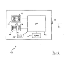
- a spectrum analyser 100 comprises a microprocessor 102 coupled to an output device, for example a Cathode Ray Tube (CRT) 104 and an input device, for example a keypad 106.
- the microprocessor 102 is also coupled to a first storage device, for example a volatile memory, such as a Random Access Memory (RAM) 108, and a second storage device, for example a non-volatile memory, such as a Read Only Memory (ROM) 109.
- RAM Random Access Memory
- ROM Read Only Memory
- the spectrum analyser 100 provides an input port 110 to which a cable 112 can be connected, the cable constituting a propagation medium through which an input signal 111 to be measured can propagate to the input port 110.
- the input port 110 is coupled to the microprocessor 102.
- the keypad 106 comprises an array of numeric keys 114; navigation keys, for example "soft" keys 116 disposed adjacent a rectangular graphical menu 400 ( Figure 4) displayed at a right hand side of the CRT 104 ; and an "enter" key 118 to confirm certain inputs.
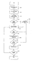
- a user powers up (step 200) the spectrum analyser 100.
- an option to carry out an MCP measurement appears in a panel (not shown) of the rectangular graphical menu 400, the option being selectable by depressing one of the soft keys 116 that is adjacent the panel (hereinafter referred to as the "MCP measurement key").
- MCP measurement key one of the soft keys 116 that is adjacent the panel.
- one end of the cable 112 is attached to the input port 110, another end of the cable 112 being coupled to a source of the input signal 111, for example a multicarrier amplifier.
- the input signal is a spread spectrum signal comprising four carrier signals, each separated by a space. A space is an absence of a carrier signal.
- a number of potential positions is provided within a predetermined band of frequencies, the positions being spectrally separated by a predetermined spectral spacing.
- a carrier signal can either be present or absent, an absence of the carrier signal power being known as the "space".
- a user depresses (step 202) the MCP measurement key.
- the microprocessor 102 retrieves (step 204) a default set of parameters. If the default set of parameters do not correspond to, or are not suitable for measurement of, the input signal 111, the user can alter the default set of parameters by navigating through an MCP measurement menu 300 ( Figure 3) using the "soft" keys 116, and modify default values of the default set of parameters using the array of numeric keys 114 and the enter key 118.
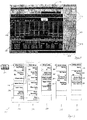
- the MCP measurement menu 300 comprises a plurality of options for setting measurement parameters. Some of the measurement parameters relate directly to measuring the input signal when the input signal comprises more than two carrier signals to be measured. Other measurement parameters relate generally to performing MCP measurements on any number of carrier signals and are known in the art and so require no further detailed description. Examples of such known measurement parameters can be found on the Agilent® E4402 or E4440 range of spectrum analysers.
- the window 402 also comprises a substantially central rectangular graphical frame 404 for displaying a spectrum of all, or part, of the input signal 406. Below the substantially central rectangular graphical frame 404, a results frame 408 is displayed for presenting the user with results of the MCP measurement.
- menu options are presented to the user, a first set of menu options 302 being for configuring measurement of power.
- Each option of the first set of menu options 302 is presented in a separate panel 410 in the menu frame 400.
- the first set of menu options 302 differ from a known first set of menu options of the Agilent® E4402 or E4440 range of spectrum analysers in that a carrier set-up panel 304 is provided and a "carrier result" panel 306 is provided, the carrier result panel 306 being used for scrolling through results displayed in the results frame 408.
- the first set of menu options permit the user to select and edit: a second set of menu options 308 for further configuration of the measurement process, and a third set of menu options 310 for configuration of offsets, bands of frequencies that flank the carrier signals.
- the configuration parameters in the first, second and third menu options 302, 308, 310 are known from the Agilent® E4402 and E4440 range of spectrum analysers and so will not be described further herein.
- the user configures the known measurement parameters contained in the first, second and third sets of menu options 302, 308, 310 in a manner known in the art.
- the user By selecting the carrier set-up panel 306 from the first set of menu options, 302, the user is presented with a fourth set of menu options 312 for configuring the MCP measurement to perform MCP measurements in respect of a number of carrier signals, for example, more than two carrier signals.
- the fourth set of menu options 312 comprises a first panel 314 for selecting a number of carrier signals from the input signal to be measured.
- a second panel 316 permits selection of one of the carrier signals from the number of carrier signals as a reference carrier signal; a specific carrier signal can be selected, or the spectrum analyser 100 can be set to automatically select the reference carrier signal, by selection of the most powerful carrier signal from the number of carrier signals.
- a third panel 318 permits the user to manually select a central frequency of the reference carrier signal, or permit the spectrum analyser 100 to select the central frequency of the reference carrier signal.
- a fourth panel 320 permits the user to access a fifth set of menu options 322 for configuring each carrier signal of the number of carrier signals. It should be appreciated that spaces can also be considered as very low power carrier signals, if requires, for the purpose of measurement.
- a configuration setting is provided for each potential location, for example, for a carrier signal, selection of a particular potential location being achieved using a fifth panel 324.
- Each potential location can be accessed by scrolling through entries using the fifth panel 324.
- a carrier power present flag, a carrier signal bandwidth setting and an integration bandwidth setting are respectively presented to the user in a sixth panel 326, a seventh panel 328 and an eighth panel 330.
- the carrier power present flag of the sixth panel 326 is used to inform the spectrum analyser 100 that the particular potential location is either a space, or contains a carrier signal. Irrespective of whether or not the particular potential location comprises the space or the carrier signal, a carrier signal bandwidth can be attributed to the particular potential location by making an appropriate entry in the seventh panel 328 using the numeric keys 114. The power at the particular location within the carrier signal bandwidth can therefore still be measured, if required. Similarly, for the purpose of measuring the power of the carrier signal or space in the particular potential location, a (carrier signal) integration bandwidth can be provided by making an appropriate entry in the eighth panel 330 using the numeric keys 114. The above data entry steps can be repeated for each potential location in order to configure each potential location for measurement of the input signal.
- the settings of the set of parameters made to configure the potential locations are applied (step 208) by the spectrum analyser 100, otherwise if the default settings have not been altered, the default settings are employed.
- the spectrum analyser 100 sweeps (step 210) the predetermined band of frequencies and again determines (step 212) whether the default settings have been altered. If the default settings have been altered by the user, the settings made by the user to configure the potential locations are applied (step 208) by the spectrum analyser 100 and the spectrum analyser 100 performs the sweep (step 210) once more. If it is determined that the settings have not been altered since the execution of the sweep, the spectrum analyser 100 measures (step 214) the power for each carrier signal/space and any selected offsets in accordance with the MCP measurement method known in the art. Once the MCP measurement has been completed, the spectrum analyser 100 determines (step 216), once again, whether the settings of the set of parameters have been altered.
- step 208 to 214 displays (step 218) the results of the MCP measurement in the results frame 408.
- the spectrum analyser determines (step 220) whether repeated sweeps are to be carried out, and if so, steps 210 to 218 are repeated, otherwise the MCP measurement is completed.
- configuration parameters have been set in order to carry out the MCP measurement in respect of the input signal containing more than two carrier signals, it should be appreciated that the principle of configuring individual potential locations is applicable to measurements of other quantities.
- Alternative embodiments of the invention can be implemented as a computer program product for use with a computer system, the computer program product being, for example, a series of computer instructions stored on a tangible data recording medium, such as a diskette, CD-ROM, ROM, or fixed disk, or embodied in a computer data signal, the signal being transmitted over a tangible medium or a wireless medium, for example microwave or infrared.
- the series of computer instructions can constitute all or part of the functionality described above, and can also be stored in any memory device, volatile or non-volatile, such as semiconductor, magnetic, optical or other memory device.
Landscapes
- Physics & Mathematics (AREA)
- Electromagnetism (AREA)
- Engineering & Computer Science (AREA)
- Computer Networks & Wireless Communication (AREA)
- Signal Processing (AREA)
- Mathematical Physics (AREA)
- General Physics & Mathematics (AREA)
- Monitoring And Testing Of Transmission In General (AREA)
Priority Applications (4)
| Application Number | Priority Date | Filing Date | Title |
|---|---|---|---|
| EP02252495A EP1351064A1 (fr) | 2002-04-06 | 2002-04-06 | Appareil de mesure avec analyseur de spectre et procédé pour celui-là |
| US10/386,983 US6882946B2 (en) | 2002-04-06 | 2003-03-12 | Spectral analysis measurement apparatus and method of measuring for spectral analysis measurement apparatus |
| CN03120836.3A CN1450741A (zh) | 2002-04-06 | 2003-03-20 | 测量装置和对应方法 |
| JP2003101956A JP2004004031A (ja) | 2002-04-06 | 2003-04-04 | 測定装置及びそのための方法 |
Applications Claiming Priority (1)
| Application Number | Priority Date | Filing Date | Title |
|---|---|---|---|
| EP02252495A EP1351064A1 (fr) | 2002-04-06 | 2002-04-06 | Appareil de mesure avec analyseur de spectre et procédé pour celui-là |
Publications (1)
| Publication Number | Publication Date |
|---|---|
| EP1351064A1 true EP1351064A1 (fr) | 2003-10-08 |
Family
ID=27838158
Family Applications (1)
| Application Number | Title | Priority Date | Filing Date |
|---|---|---|---|
| EP02252495A Withdrawn EP1351064A1 (fr) | 2002-04-06 | 2002-04-06 | Appareil de mesure avec analyseur de spectre et procédé pour celui-là |
Country Status (4)
| Country | Link |
|---|---|
| US (1) | US6882946B2 (fr) |
| EP (1) | EP1351064A1 (fr) |
| JP (1) | JP2004004031A (fr) |
| CN (1) | CN1450741A (fr) |
Families Citing this family (6)
| Publication number | Priority date | Publication date | Assignee | Title |
|---|---|---|---|---|
| US20090158197A1 (en) * | 2004-01-09 | 2009-06-18 | Koninklijke Philips Electronic, N.V. | Two panel navigation |
| US7769372B1 (en) * | 2004-07-08 | 2010-08-03 | National Semiconductor Corporation | Selectively activated multi-subcarrier (SAMS) radio transceiver measuring techniques |
| CN1866800B (zh) * | 2006-03-22 | 2010-04-14 | 华为技术有限公司 | 对发射机的指标进行测试的方法和测试系统 |
| US8365282B2 (en) * | 2007-07-18 | 2013-01-29 | Research In Motion Limited | Security system based on input shortcuts for a computer device |
| CN102749511B (zh) | 2012-06-12 | 2015-08-12 | 大唐移动通信设备有限公司 | 分布式频谱分析仪及应用其进行频谱分析的方法 |
| US10693570B2 (en) * | 2018-08-20 | 2020-06-23 | Rohde & Schwarz Gmbh & Co. Kg | Device and method of analyzing a radio frequency signal |
Citations (3)
| Publication number | Priority date | Publication date | Assignee | Title |
|---|---|---|---|---|
| EP0977384A1 (fr) * | 1998-07-31 | 2000-02-02 | Hewlett-Packard Company | Procédé et dispositif de mesure d'un spectre de l'energy pour un appareil mobile |
| US6263289B1 (en) * | 1998-12-23 | 2001-07-17 | Agilent Technologies Inc. | Method of enhancing the dynamic range of intermodulation distortion measurements |
| US20020027961A1 (en) * | 2000-09-07 | 2002-03-07 | Leonard Rexberg | Off-line MCPA calibration |
Family Cites Families (6)
| Publication number | Priority date | Publication date | Assignee | Title |
|---|---|---|---|---|
| US6201955B1 (en) * | 1998-05-29 | 2001-03-13 | Motorola, Inc. | Method and apparatus for receiving a radio frequency signal using a plurality of antennas |
| US6512788B1 (en) * | 1998-11-02 | 2003-01-28 | Agilent Technologies, Inc. | RF output spectrum measurement analyzer and method |
| US6590587B1 (en) * | 1999-11-30 | 2003-07-08 | Agilent Technologies, Inc. | Monitoring system and method implementing navigation interface logic |
| EP1237339A1 (fr) * | 2001-03-01 | 2002-09-04 | Alcatel | Récepteur multiporteuse capable d'estimer la perturbation haute fréquence |
| US6829471B2 (en) * | 2001-03-07 | 2004-12-07 | Andrew Corporation | Digital baseband receiver in a multi-carrier power amplifier |
| US6937952B2 (en) * | 2001-07-12 | 2005-08-30 | Ses Americom, Inc. | Satellite carrier measurement system and method |
-
2002
- 2002-04-06 EP EP02252495A patent/EP1351064A1/fr not_active Withdrawn
-
2003
- 2003-03-12 US US10/386,983 patent/US6882946B2/en not_active Expired - Fee Related
- 2003-03-20 CN CN03120836.3A patent/CN1450741A/zh active Pending
- 2003-04-04 JP JP2003101956A patent/JP2004004031A/ja active Pending
Patent Citations (3)
| Publication number | Priority date | Publication date | Assignee | Title |
|---|---|---|---|---|
| EP0977384A1 (fr) * | 1998-07-31 | 2000-02-02 | Hewlett-Packard Company | Procédé et dispositif de mesure d'un spectre de l'energy pour un appareil mobile |
| US6263289B1 (en) * | 1998-12-23 | 2001-07-17 | Agilent Technologies Inc. | Method of enhancing the dynamic range of intermodulation distortion measurements |
| US20020027961A1 (en) * | 2000-09-07 | 2002-03-07 | Leonard Rexberg | Off-line MCPA calibration |
Also Published As
| Publication number | Publication date |
|---|---|
| US20030191595A1 (en) | 2003-10-09 |
| JP2004004031A (ja) | 2004-01-08 |
| CN1450741A (zh) | 2003-10-22 |
| US6882946B2 (en) | 2005-04-19 |
Similar Documents
| Publication | Publication Date | Title |
|---|---|---|
| KR100261831B1 (ko) | Cn비 측정장치 | |
| US6567762B2 (en) | Dynamic range extension apparatus and method | |
| US8527229B2 (en) | Test systems with multiple antennas for characterizing over-the-air path loss | |
| CN101738604B (zh) | 一种毫米波接收机自动测试系统 | |
| MX2010013967A (es) | Metodo para probar un receptor de frecuencia de radio (rf) para proporcionar datos de correccion de energia. | |
| CN1983828A (zh) | 一种终端杂散测试系统和方法 | |
| US6882946B2 (en) | Spectral analysis measurement apparatus and method of measuring for spectral analysis measurement apparatus | |
| US7020096B2 (en) | Physical quantity display device for displaying physical quantity of multiple signals, method and recording medium | |
| CN114039676B (zh) | 射频测试机和射频测试机的校准方法 | |
| CN106788786B (zh) | 标准化卫星射频指标测试系统 | |
| GB2313723A (en) | Controlling the output power of a mobile phone using a look-up table for attenuation values and frequencies | |
| US3908165A (en) | Field strength meter | |
| US5974362A (en) | Signal generator for testing radio frequency components | |
| CA2873728A1 (fr) | Procede et systeme permettant d'analyser une sensibilite au brouillage d'une conception d'un recepteur radio | |
| JP6484263B2 (ja) | 画面分割表示装置、それを備えた測定装置、及び画面分割表示方法 | |
| CN111224723B (zh) | 射频前端模块的校准方法、系统、电子设备及存储介质 | |
| CN113810129A (zh) | 一种5g nr测试方法、装置、终端及存储介质 | |
| CN102546045B (zh) | 无线装置的传输功率校验方法及其系统 | |
| CN107835056B (zh) | 一种多信道功率测量及显示方法和装置 | |
| JP6127073B2 (ja) | パラメータ設定装置及びパラメータ設定方法 | |
| US20090047918A1 (en) | Mix and Match Preselector and RF Receiver | |
| CN103248438B (zh) | 测定装置及测定方法 | |
| CN111083626B (zh) | 麦克风抗射频干扰性能的测试方法、设备和系统 | |
| US6784655B2 (en) | Method of setting gribs and/or markers in measuring apparatus | |
| CN108111241B (zh) | 一种直放站检测方法 |
Legal Events
| Date | Code | Title | Description |
|---|---|---|---|
| PUAI | Public reference made under article 153(3) epc to a published international application that has entered the european phase |
Free format text: ORIGINAL CODE: 0009012 |
|
| AK | Designated contracting states |
Kind code of ref document: A1 Designated state(s): AT BE CH CY DE DK ES FI FR GB GR IE IT LI LU MC NL PT SE TR |
|
| AX | Request for extension of the european patent |
Extension state: AL LT LV MK RO SI |
|
| 17P | Request for examination filed |
Effective date: 20040408 |
|
| AKX | Designation fees paid |
Designated state(s): DE FR GB |
|
| 17Q | First examination report despatched |
Effective date: 20061211 |
|
| RAP1 | Party data changed (applicant data changed or rights of an application transferred) |
Owner name: AGILENT TECHNOLOGIES, INC. |
|
| STAA | Information on the status of an ep patent application or granted ep patent |
Free format text: STATUS: THE APPLICATION IS DEEMED TO BE WITHDRAWN |
|
| 18D | Application deemed to be withdrawn |
Effective date: 20070424 |