The present invention relates to a measuring apparatus of the type used, for
example, to measure power of a carrier signal constituting a Radio Frequency
(RF) channel, such as a transmit channel of an RF communications systems.
The present invention also relates to a method of measuring power, for
example, of the carrier signal.
Manufacturers of receiver amplifiers for use in spread-spectrum
communications systems have a requirement to test outputs of the amplifiers
during development and quality control processes associated with manufacture
of the amplifiers. In this respect, it is necessary to test for correct amplification
of carrier signals by a given amplifier and the effect of amplified carrier signals
on adjacent, or other, carrier signals. One test for correct amplification of the
input carrier signals involves measurement of power, within a predetermined
band of frequencies, of amplified carrier signals and predetermined spaces
absent of the amplified carrier signals generated by the given amplifier.
A first known measurement is an Adjacent Channel Power (ACP)
measurement; a measure of absolute power leakage from a given transmit
channel to adjacent transmit channels. However, the ACP measurement is
only made with respect to a single carrier signal, and where more than one
channel exists, the absolute power is only measured with respect to a main
carrier signal.
A second known measurement is a Multi-Carrier Power (MCP) measurement; a
measure of absolute power in two transmit channels, and absolute power
leakage into adjacent transmit channels. However, the MCP measurement is
currently limited to measuring two carrier signals, each having a bandwidth of 5
MHz and a maximum separation of 15 MHz.
Given the number of RF communications systems standards ("radio
standards") in existence, for example Wideband-Code Division Multiple Access
(W-CDMA), IS-95 and cdma2000, now employing more than two carrier
signals, test equipment designed to perform the measurements as described
above are either incapable of providing a meaningful measure of power with
respect to all carrier signals of a given radio standard, or are incapable of
automatically providing a measurement of all carrier signals, when more than
two carrier signals exist, of the given radio standard.
According to a first aspect of the present invention, there is provided a
measuring apparatus comprising a spectrum analysis unit having an input for
receiving an input signal to be measured, the input signal comprising a carrier
signal located within a predetermined frequency band; characterised in that: the
spectrum analysis unit is arranged to store, a set of parameters comprising the
location of the carrier signal within the band of frequencies, and use the set of
parameters to measure a quantity associated with the carrier signal.
Preferably, the set of parameters further comprises a bandwidth of the carrier
signal.
Preferably, the set of parameters further comprises a measurement bandwidth,
the spectrum analysis unit being arranged to measure the quantity substantially
over the measurement bandwidth. More preferably, the measurement
bandwidth is an integration bandwidth.
Preferably, the set of parameters further comprises an identification of the set
of parameters.
Preferably, the set of parameters further comprises an indication of the
presence of the carrier signal at the location within the predetermined band of
frequencies.
Preferably, the set of parameters further comprises an identification that the
carrier signal is a reference carrier signal.
Preferably, the set of parameters further comprises an identification of a
frequency corresponding to a location of a reference carrier signal.
Preferably, the input signal comprises more than two carrier signals, the set of
parameters further comprising respective locations of the more than two carrier
signals within the band of frequencies.
Preferably, the property associated with the carrier frequency to be measured
is power.
Preferably, the set of parameters is user-definable. The set of parameters may
be set remotely using, for example, a Standard Commands for Programmable
Instruments (SCPI) command.
In a preferred embodiment, a spectrum analyser is provided comprising the
measuring apparatus as set forth above in accordance with the first aspect of
the present invention.
According to a second aspect of the present invention, there is provided a
method of measuring for a measuring apparatus comprising a spectrum
analysis unit having an input for receiving an input signal to be measured, the
method comprising the following steps: receiving an input signal, the input
signal comprising a carrier signal located within a predetermined frequency
band; the method being characterised by: storing a set of parameters
comprising the location of the carrier signal within the band of frequencies; and
using the set of parameters to measure the quantity associated with the carrier
signal.
According to a third aspect of the present invention, there is provided a
computer program element comprising computer program code means
arranged to make a computer execute the method as set forth above in
accordance with the second aspect of the present invention.
Preferably, the computer program element is embodied on a computer
readable medium.
It is thus possible to provide a measuring apparatus and a method therefor that
permits a user to perform an MCP measurement in respect of carrier signals
employed in a radio standard, in particular where more than two carrier signals
are to be measured. The present invention obviates the need to measure
power of each carrier signal separately, thereby greatly increasing the speed
and hence efficiency of the MCP measurement. Additionally, it is possible to
make measurements in respect of any combination of carrier signals and
spaces (absences of carrier signals) within the predetermined band of
frequencies. Also, by permitting the users to measure carrier signals of
different bandwidths, greater flexibility is provided to users, because carrier
signals of a larger number of different radio standards can be measured than
was previously possible, the bandwidth of carrier signals varying between radio
standards. Furthermore, efficiency in measuring the carrier signals is also
improved, since separate sets of configuration parameters can be readily
accessed/input for each carrier signal/space. An additional efficiency is
achieved by virtue of the ability to set all, or substantially all, of the sets of
parameters prior to making measurements, thereby enabling continual,
uninterrupted, measurements to be made. The use of the SCPI command
permits a given parameter to be set for a number of locations using a single
SCPI command, thus also improving efficiency of the measurement process.
At least one embodiment of the invention will now be described, by way of
example only, with reference to the accompanying drawings, in which:
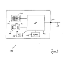
Referring to Figure 1, a spectrum analyser 100 comprises a microprocessor
102 coupled to an output device, for example a Cathode Ray Tube (CRT) 104
and an input device, for example a keypad 106. The microprocessor 102 is
also coupled to a first storage device, for example a volatile memory, such as a
Random Access Memory (RAM) 108, and a second storage device, for
example a non-volatile memory, such as a Read Only Memory (ROM) 109. It
should, of course, be appreciated that other storage means can be employed in
place of, or in addition to, the RAM 108 and/or the ROM 109. The spectrum
analyser 100 provides an input port 110 to which a cable 112 can be
connected, the cable constituting a propagation medium through which an input
signal 111 to be measured can propagate to the input port 110. The input port
110 is coupled to the microprocessor 102.
The keypad 106 comprises an array of numeric keys 114; navigation keys, for
example "soft" keys 116 disposed adjacent a rectangular graphical menu 400
(Figure 4) displayed at a right hand side of the CRT 104 ; and an "enter" key
118 to confirm certain inputs.
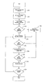
In operation (Figure 2), a user powers up (step 200) the spectrum analyser
100. Upon power-up, an option to carry out an MCP measurement appears in
a panel (not shown) of the rectangular graphical menu 400, the option being
selectable by depressing one of the soft keys 116 that is adjacent the panel
(hereinafter referred to as the "MCP measurement key"). Subsequently, one
end of the cable 112 is attached to the input port 110, another end of the cable
112 being coupled to a source of the input signal 111, for example a multicarrier
amplifier. In this example, the input signal is a spread spectrum signal
comprising four carrier signals, each separated by a space. A space is an
absence of a carrier signal. In a given radio standard, for example W-CDMA, a
number of potential positions is provided within a predetermined band of
frequencies, the positions being spectrally separated by a predetermined
spectral spacing. At each of the number of locations, a carrier signal can either
be present or absent, an absence of the carrier signal power being known as
the "space".
In order to make an MCP measurement of the input signal 111, a user
depresses (step 202) the MCP measurement key. In response to depressing
the MCP measurement key, the microprocessor 102 retrieves (step 204) a
default set of parameters. If the default set of parameters do not correspond to,
or are not suitable for measurement of, the input signal 111, the user can alter
the default set of parameters by navigating through an MCP measurement
menu 300 (Figure 3) using the "soft" keys 116, and modify default values of the
default set of parameters using the array of numeric keys 114 and the enter key
118.
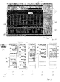
Referring to Figure 3, the MCP measurement menu 300 comprises a plurality
of options for setting measurement parameters. Some of the measurement
parameters relate directly to measuring the input signal when the input signal
comprises more than two carrier signals to be measured. Other measurement
parameters relate generally to performing MCP measurements on any number
of carrier signals and are known in the art and so require no further detailed
description. Examples of such known measurement parameters can be found
on the Agilent® E4402 or E4440 range of spectrum analysers.
Referring to Figure 4, upon depression of the MCP measurement key, sets of
menu options are presented to the user in the rectangular graphical menu 400
on the right hand side of a window 402 displayed by the CRT 104.
Functionality of the soft keys 116 depends upon the menu options presented in
the rectangular graphical menu 400; as the menu options change so do the
respective functionalities of the soft keys 116. The window 402 also
comprises a substantially central rectangular graphical frame 404 for displaying
a spectrum of all, or part, of the input signal 406. Below the substantially
central rectangular graphical frame 404, a results frame 408 is displayed for
presenting the user with results of the MCP measurement.
As mentioned above, upon an initial depression of the MCP measurement key,
menu options are presented to the user, a first set of menu options 302 being
for configuring measurement of power. Each option of the first set of menu
options 302 is presented in a separate panel 410 in the menu frame 400. The
first set of menu options 302 differ from a known first set of menu options of the
Agilent® E4402 or E4440 range of spectrum analysers in that a carrier set-up
panel 304 is provided and a "carrier result" panel 306 is provided, the carrier
result panel 306 being used for scrolling through results displayed in the results
frame 408. The first set of menu options permit the user to select and edit: a
second set of menu options 308 for further configuration of the measurement
process, and a third set of menu options 310 for configuration of offsets, bands
of frequencies that flank the carrier signals. The configuration parameters in
the first, second and third menu options 302, 308, 310 are known from the
Agilent® E4402 and E4440 range of spectrum analysers and so will not be
described further herein.
In accordance with a test scheme devised by the user requiring the execution
of the MCP measurement, the user configures the known measurement
parameters contained in the first, second and third sets of menu options 302,
308, 310 in a manner known in the art. By selecting the carrier set-up panel
306 from the first set of menu options, 302, the user is presented with a fourth
set of menu options 312 for configuring the MCP measurement to perform MCP
measurements in respect of a number of carrier signals, for example, more
than two carrier signals. The fourth set of menu options 312 comprises a first
panel 314 for selecting a number of carrier signals from the input signal to be
measured. A second panel 316 permits selection of one of the carrier signals
from the number of carrier signals as a reference carrier signal; a specific
carrier signal can be selected, or the spectrum analyser 100 can be set to
automatically select the reference carrier signal, by selection of the most
powerful carrier signal from the number of carrier signals. A third panel 318
permits the user to manually select a central frequency of the reference carrier
signal, or permit the spectrum analyser 100 to select the central frequency of
the reference carrier signal. A fourth panel 320 permits the user to access a
fifth set of menu options 322 for configuring each carrier signal of the number of
carrier signals. It should be appreciated that spaces can also be considered as
very low power carrier signals, if requires, for the purpose of measurement.
A configuration setting is provided for each potential location, for example, for a
carrier signal, selection of a particular potential location being achieved using a
fifth panel 324. Each potential location can be accessed by scrolling through
entries using the fifth panel 324. Once a particular potential location has been
selected using the fifth panel 324, a carrier power present flag, a carrier signal
bandwidth setting and an integration bandwidth setting are respectively
presented to the user in a sixth panel 326, a seventh panel 328 and an eighth
panel 330.
The carrier power present flag of the sixth panel 326 is used to inform the
spectrum analyser 100 that the particular potential location is either a space, or
contains a carrier signal. Irrespective of whether or not the particular potential
location comprises the space or the carrier signal, a carrier signal bandwidth
can be attributed to the particular potential location by making an appropriate
entry in the seventh panel 328 using the numeric keys 114. The power at the
particular location within the carrier signal bandwidth can therefore still be
measured, if required. Similarly, for the purpose of measuring the power of the
carrier signal or space in the particular potential location, a (carrier signal)
integration bandwidth can be provided by making an appropriate entry in the
eighth panel 330 using the numeric keys 114. The above data entry steps can
be repeated for each potential location in order to configure each potential
location for measurement of the input signal.
Referring back to Figure 2, once completion of configuration of the potential
locations has been determined (step 206), the settings of the set of parameters
made to configure the potential locations are applied (step 208) by the
spectrum analyser 100, otherwise if the default settings have not been altered,
the default settings are employed.
In accordance with the settings, the spectrum analyser 100 sweeps (step 210)
the predetermined band of frequencies and again determines (step 212)
whether the default settings have been altered. If the default settings have
been altered by the user, the settings made by the user to configure the
potential locations are applied (step 208) by the spectrum analyser 100 and the
spectrum analyser 100 performs the sweep (step 210) once more. If it is
determined that the settings have not been altered since the execution of the
sweep, the spectrum analyser 100 measures (step 214) the power for each
carrier signal/space and any selected offsets in accordance with the MCP
measurement method known in the art. Once the MCP measurement has
been completed, the spectrum analyser 100 determines (step 216), once again,
whether the settings of the set of parameters have been altered. If the settings
have been altered, steps 208 to 214 are repeated, otherwise the spectrum
analyser 100 displays (step 218) the results of the MCP measurement in the
results frame 408. The spectrum analyser then determines (step 220) whether
repeated sweeps are to be carried out, and if so, steps 210 to 218 are
repeated, otherwise the MCP measurement is completed.
Although, in the above example, configuration parameters have been set in
order to carry out the MCP measurement in respect of the input signal
containing more than two carrier signals, it should be appreciated that the
principle of configuring individual potential locations is applicable to
measurements of other quantities.
Alternative embodiments of the invention can be implemented as a computer
program product for use with a computer system, the computer program
product being, for example, a series of computer instructions stored on a
tangible data recording medium, such as a diskette, CD-ROM, ROM, or fixed
disk, or embodied in a computer data signal, the signal being transmitted over a
tangible medium or a wireless medium, for example microwave or infrared.
The series of computer instructions can constitute all or part of the functionality
described above, and can also be stored in any memory device, volatile or non-volatile,
such as semiconductor, magnetic, optical or other memory device.