EP1351042B1 - Verfahren und Vorrichtung zum Messen eines optischen Spektrums - Google Patents
Verfahren und Vorrichtung zum Messen eines optischen Spektrums Download PDFInfo
- Publication number
- EP1351042B1 EP1351042B1 EP20020010795 EP02010795A EP1351042B1 EP 1351042 B1 EP1351042 B1 EP 1351042B1 EP 20020010795 EP20020010795 EP 20020010795 EP 02010795 A EP02010795 A EP 02010795A EP 1351042 B1 EP1351042 B1 EP 1351042B1
- Authority
- EP
- European Patent Office
- Prior art keywords
- filter
- broadband
- narrow
- wavelength range
- measured
- Prior art date
- Legal status (The legal status is an assumption and is not a legal conclusion. Google has not performed a legal analysis and makes no representation as to the accuracy of the status listed.)
- Expired - Lifetime
Links
- 238000001228 spectrum Methods 0.000 title claims description 60
- 230000003287 optical effect Effects 0.000 title claims description 36
- 238000000034 method Methods 0.000 title claims description 19
- 238000005259 measurement Methods 0.000 title claims description 7
- 238000011156 evaluation Methods 0.000 claims description 10
- 230000000737 periodic effect Effects 0.000 claims description 3
- 230000003595 spectral effect Effects 0.000 description 15
- 230000008901 benefit Effects 0.000 description 4
- BJQHLKABXJIVAM-UHFFFAOYSA-N bis(2-ethylhexyl) phthalate Chemical compound CCCCC(CC)COC(=O)C1=CC=CC=C1C(=O)OCC(CC)CCCC BJQHLKABXJIVAM-UHFFFAOYSA-N 0.000 description 2
- 238000001514 detection method Methods 0.000 description 2
- 101100390736 Danio rerio fign gene Proteins 0.000 description 1
- 101100390738 Mus musculus Fign gene Proteins 0.000 description 1
- 239000002131 composite material Substances 0.000 description 1
- 238000001914 filtration Methods 0.000 description 1
- 230000035945 sensitivity Effects 0.000 description 1
- 230000001629 suppression Effects 0.000 description 1
Images



Classifications
-
- G—PHYSICS
- G01—MEASURING; TESTING
- G01J—MEASUREMENT OF INTENSITY, VELOCITY, SPECTRAL CONTENT, POLARISATION, PHASE OR PULSE CHARACTERISTICS OF INFRARED, VISIBLE OR ULTRAVIOLET LIGHT; COLORIMETRY; RADIATION PYROMETRY
- G01J3/00—Spectrometry; Spectrophotometry; Monochromators; Measuring colours
- G01J3/28—Investigating the spectrum
- G01J3/30—Measuring the intensity of spectral lines directly on the spectrum itself
- G01J3/32—Investigating bands of a spectrum in sequence by a single detector
-
- G—PHYSICS
- G01—MEASURING; TESTING
- G01J—MEASUREMENT OF INTENSITY, VELOCITY, SPECTRAL CONTENT, POLARISATION, PHASE OR PULSE CHARACTERISTICS OF INFRARED, VISIBLE OR ULTRAVIOLET LIGHT; COLORIMETRY; RADIATION PYROMETRY
- G01J3/00—Spectrometry; Spectrophotometry; Monochromators; Measuring colours
- G01J3/12—Generating the spectrum; Monochromators
- G01J3/26—Generating the spectrum; Monochromators using multiple reflection, e.g. Fabry-Perot interferometer, variable interference filters
Definitions
- the invention relates to a method and a device for measuring a optical spectrum.
- Known measuring methods use a tunable broadband and a tunable narrowband optical filter.
- the Match the center wavelengths of the two filters respectively.
- the synchronization of the center wavelengths of the two filters is a considerable one Control effort required.
- the invention is based on the object, a method and a Device for measuring an optical spectrum with the lowest possible To realize control effort.
- a second low bandwidth filter is connected in series. According to the invention does not try to match the center wavelength of the two filters but the center wavelength of the narrow band filter is only at a much higher speed than the broadband filter wobbled over the predetermined wavelength range. The knowledge of the situation the center frequency of the narrow band filter is not required, so that a very simple filter can be used.
- the high accuracy of the center wavelength of the broadband filter can by various methods are achieved, e.g. constructive by accurate Adjustment, by metrological detection of the rotation angle of a grid, by metrological detection of the plate spacing of an etalon, through Comparison with a particular spectrum etc.
- its respective Center wavelength can be measured.
- the output spectrum is calculated from the measured optical Spectra of several passes of the narrowband filter composed.
- the spectral lines of the input spectrum to be measured with the Separate the high resolution of the narrow-band filter and its wavelength with the accuracy of the broadband filter.
- the invention enables the increase in the resolution of a broadband optical filter by adding a narrowband optical filter without mutual synchronization.
- This can be a very simple narrow band filter can be used.
- the control effort is minimal.
- the broadband filter is set precisely, the exact one needs Center wavelength of the narrow-band filter to be known at any time. It Therefore, simple embodiments such as e.g. rotating or swinging dispersive elements, oscillating or detuned Fabry-Perot resonators, Fiber Bragg Grating (FBG) filters or other arrangements suitable.
- rotating or swinging dispersive elements oscillating or detuned Fabry-Perot resonators, Fiber Bragg Grating (FBG) filters or other arrangements suitable.
- FBG Fiber Bragg Grating
- the narrow-band filter may be ambiguous, provided that only the distance of the passbases of different orders is so great that the broadband filter sufficiently large suppression of the other Has orders.
- Another advantage is that rotating or one Self-resonant vibrating filters are driven very energy efficient can.
- the broadband filter is stepped over the tuned predetermined wavelength range.
- This gradually Voting can also be done by selecting a filter path from a number parallel paths, e.g. by switching over a fixed multiplexer.
- the use of a spectrometer in front of a digital camera is the same Switch from pixel to pixel.
- Advantage of the stepwise scanning is that lower demands on the speed of the narrowband filter and the subsequent recipient.
- the broadband filter is continuous tuned over the predetermined wavelength range.
- the narrow-band filter is advantageous periodically tune.
- the narrow-band filter is ambiguous and is scanned step by step, e.g. through a camera behind a periodic spectrometer.
- An embodiment is for example the Arrangement of a CCD camera behind a phased array.
- a Device with a tunable, broadband optical filter and a tunable, narrow band optical filter, both connected in series are, with a downstream detector and with an evaluation to find that intensity value in each measured optical Spectrum, each at one wavelength the maximum intensity of all measured spectra, and to put together all the found Intensity values over the respectively associated center wavelength of their measured Spectra to an output spectrum.
- the Speed at which the narrowband filter periodically over a predetermined wavelength range is tuned considerably higher than that Speed at which the broadband filter periodically over the predetermined wavelength range is tuned.
- the speeds depend on the predetermined wavelength range of the available standing time, the desired resolution and the uniqueness range of the narrow band filter. Should e.g. a spectral range of 100 nm in 10 s be measured with a resolution of 0.01 nm and is the narrowband Filter also clearly above 100 nm, so the speed of the broadband filter 10nm / s and narrowband filter> 100000nm / s be.
- the broadband filter has one in the predetermined Wavelength range unique and the narrow-band filter a periodic Filter characteristic.
- the broadband filter may e.g. a grid monochromator and the narrowband filter e.g. be a Fabry-Perot filter.
- the usage an ambiguous narrowband filter allows a much lower one Speed, because the narrow-band filter does not cover the whole predetermined wavelength range must be detuned. This lower one Speed benefits the sensitivity of the device.
- the narrowband filter can be behind or in front of the broadband filter be arranged.
- the device 1 shown in Fig. 1 is used for measuring an optical spectrum and 2 comprises a tunable with high precision, broadband optical filter 3, an example designed as a photodiode detector 4 and an intermediate tunable narrowband optical filter 5. Both filters 3, 5 are tuned periodically over the same measuring wavelength range, wherein the center wavelength of the narrow-band filter 5 is wobbled at a significantly higher speed than the center wavelength ⁇ 0 of the broadband filter 3 over the measuring wavelength range.
- the respective center wavelength ⁇ 0i of the broadband filter 3 is set or measured with a device, not shown, and supplied together with the associated spectrum 7 to the evaluation device 6, as indicated in Fig. 1 by the dashed line 8 .
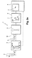
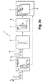
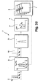
- FIGS. 2 and 3 describe the individual method steps of the measuring method carried out with the device 1 using the example of an optical spectrum 9 to be measured with only two spectral lines ⁇ 1 , ⁇ 2 ( ⁇ 1 ⁇ 2 ) of the same intensity I 0 :
- the center wavelength ⁇ 0 of the broadband filter 3 is set to a wavelength ⁇ 01 ( ⁇ 01 ⁇ 1 ), so that at the output 10 of the broadband filter 3, the two spectral lines ⁇ 1 , ⁇ 2 in intensity corresponding to the filter curve edge of the broadband filter 3 are reduced.
- the narrow-band filter 5 is tuned once at the set center wavelength ⁇ 01 over the measurement wavelength range and simultaneously measured with the detector 4, the associated optical spectrum 7, which is then stored in the evaluation device 6 as I ⁇ 01 (t) spectrum.
- the narrow-band filter 5 is tuned once over the measuring wavelength range at the set central wavelength ⁇ 02 and at the same time the associated optical spectrum 7 is measured with the detector 4, which is then stored in the evaluation device 6 as I ⁇ 02 (t) spectrum.
- the center wavelength ⁇ 0 of the broadband filter 3 is set to a wavelength ⁇ 03 ( ⁇ 1 ⁇ 03 ⁇ 2 ), so that at the output 10 of the broadband filter 3 both spectral lines ⁇ 1 , ⁇ 2 in accordance with their intensity the filter curve edges of the broadband filter 3 are reduced.
- the narrow-band filter 5 is tuned once at the set center wavelength ⁇ 03 over the measurement wavelength range and simultaneously measured with the detector 4, the associated optical spectrum 7, which is then stored in the evaluation device 6 as I ⁇ 03 (t) spectrum.
- the narrow-band filter 5 is tuned once at the set center wavelength ⁇ 04 over the measurement wavelength range and simultaneously measured with the detector 4, the associated optical spectrum 7, which is then stored in the evaluation device 6 as I ⁇ 04 (t) spectrum.
- the center wavelength ⁇ 05 of the broadband filter 3 is set to a wavelength ⁇ 05 > ⁇ 2 , so that at the output 10 of the broadband filter 3 both spectral lines ⁇ 1 , ⁇ 2 reduces in intensity according to the filter curve edge of the broadband filter 3 are.
- the narrow-band filter 5 is tuned once at the set center wavelength ⁇ 05 over the measurement wavelength range and simultaneously measured with the detector 4, the associated optical spectrum 7, which is then stored in the evaluation device 6 as I ⁇ 05 (t) spectrum.
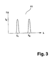
- the output spectrum with the resolution of the narrowband filter 5 is obtained, taking into account the filter values of the two filters 3, 5 at their center wavelengths.
- the spectral lines of the input spectrum 2 are separated high resolution of the narrow-band filter 5 and determines their wavelengths with the accuracy of the broadband filter 3.
- the two spectral lines ⁇ 1 , ⁇ 2 of the input signal 2 are separated in the output spectrum 11 with the high resolution of the narrow-band filter 5 and their wavelengths determined with the accuracy of the broadband filter 3.
Landscapes
- Physics & Mathematics (AREA)
- Spectroscopy & Molecular Physics (AREA)
- General Physics & Mathematics (AREA)
- Spectrometry And Color Measurement (AREA)
Description
- Fig. 1
- schematisch die wesentlichen Teile der erfindungsgemäßen Messvorrichtung;
- Fign. 2a-2e
- mit der Messvorrichtung der Fig. 1 gemessene optische Spektren mehrerer Durchläufe des schmalbandigen Filters bei jeweils unterschiedlichen Mittenwellenlängen des breitbandigen Filters am Beispiel eines optischen Spektrums mit zwei Spektrallinien;
- Fig. 3
- das aus den gemessenen Spektren der Fig. 2 zusammengesetzte optische Ausgangsspektrum.
Claims (10)
- Verfahren zum Messen eines optischen Spektrums (2) innerhalb eines vorbestimmten Wellenlängenbereichs, mit folgenden Verfahrensschritten: Durchstimmen eines abstimmbaren breitbandigen optischen Filters (3) über den vorbestimmten Wellenlängenbereich mit hoher Genauigkeit seiner jeweiligen Mittenwellenlänge (λ0),
Durchstimmen eines in Reihe mit dem breitbandigen Filter (3) geschalteten, abstimmbaren schmalbandigen optischen Filters (5) über den vorbestimmten Wellenlängenbereich bei jeweils unterschiedlichen Mittenwellenlängen (λ0) des breitbandigen Filters (3) und gleichzeitiges Messen der zugehörigen optischen Spektren (7),
Auffinden desjenigen einen Intensitätswerts in jedem gemessenen Spektrum (7), der jeweils bei einer Wellenlänge die maximale Intensität aller gemessenen Spektren (7) hat, und
Zusammensetzen aller aufgefundenen Intensitätswerte über die jeweils zugehörige Mittenwellenlänge (λ0) ihrer gemessenen Spektren (7) zu einem Ausgangsspektrum (11). - Verfahren nach Anspruch 1, dadurch gekennzeichnet, dass beim Durchstimmen des breitbandigen Filters (3) gleichzeitig seine Mittenwellenlänge gemessen wird.
- Verfahren nach Anspruch 1 oder 2, dadurch gekennzeichnet, dass der breitbandige Filter (3) schrittweise über den vorbestimmten Wellenlängenbereich durchgestimmt wird.
- Verfahren nach Anspruch 1 oder 2, dadurch gekennzeichnet, dass das breitbandige Filter (3) kontinuierlich über den vorbestimmten Wellenlängenbereich durchgestimmt wird.
- Verfahren nach einem der vorhergehenden Ansprüche, dadurch gekennzeichnet, dass das breitbandige Filter (3) und/oder das schmalbandige Filter (5) periodisch über den vorbestimmten Wellenlängenbereich durchgestimmt werden.
- Vorrichtung (1) zur Durchführung des Verfahrens nach einem der vorhergehenden Ansprüche, mit einem abstimmbaren, breitbandigen optischen Filter (3) und einem abstimmbaren, schmalbandigen optischen Filter (5), die beide in Reihe geschaltet sind, mit einem nachgeschalteten Detektor (4) und mit einer Auswerteeinrichtung (6) zum Auffinden desjenigen Intensitätswerts in jedem gemessenen optischen Spektrum (7), der jeweils bei einer Wellenlänge die maximale Intensität aller gemessenen Spektren (7) hat, und zum Zusammensetzen aller aufgefundenen Intensitätswerte über die jeweils zugehörige Mittenwellenlänge (λ0) ihrer gemessenen Spektren (7) zu einem Ausgangsspektrum (11).
- Vorrichtung nach Anspruch 6, dadurch gekennzeichnet, dass die Geschwindigkeit, mit welcher das schmalbandige Filter (5) periodisch über einen vorbestimmten Wellenlängenbereich durchgestimmt wird, höher ist als die Geschwindigkeit, mit welcher das breitbandige Filter (3) periodisch über den vorbestimmten Wellenlängenbereich durchgestimmt wird.
- Vorrichtung nach Anspruch 6 oder 7, dadurch gekennzeichnet, dass das breitbandige Filter (3) eine im vorbestimmten Wellenlängenbereich eindeutige und das schmalbandige Filter (5) eine periodische Filtercharakteristik hat.
- Vorrichtung nach einem der Ansprüche 6 bis 8, dadurch gekennzeichnet, dass das schmalbandige Filter (5) ein Fabry-Perot-Filter ist.
- Vorrichtung nach einem der Ansprüche 6 bis 8 dadurch gekennzeichnet, dass das schmalbandige Filter (5) ein Fiber-Bragg-Grating-(FBG)-Filter ist.
Priority Applications (2)
| Application Number | Priority Date | Filing Date | Title |
|---|---|---|---|
| DE50201771T DE50201771D1 (de) | 2002-05-15 | 2002-05-15 | Verfahren und Vorrichtung zum Messen eines optischen Spektrums |
| EP20020010795 EP1351042B1 (de) | 2002-05-15 | 2002-05-15 | Verfahren und Vorrichtung zum Messen eines optischen Spektrums |
Applications Claiming Priority (1)
| Application Number | Priority Date | Filing Date | Title |
|---|---|---|---|
| EP20020010795 EP1351042B1 (de) | 2002-05-15 | 2002-05-15 | Verfahren und Vorrichtung zum Messen eines optischen Spektrums |
Publications (2)
| Publication Number | Publication Date |
|---|---|
| EP1351042A1 EP1351042A1 (de) | 2003-10-08 |
| EP1351042B1 true EP1351042B1 (de) | 2004-12-15 |
Family
ID=27838086
Family Applications (1)
| Application Number | Title | Priority Date | Filing Date |
|---|---|---|---|
| EP20020010795 Expired - Lifetime EP1351042B1 (de) | 2002-05-15 | 2002-05-15 | Verfahren und Vorrichtung zum Messen eines optischen Spektrums |
Country Status (2)
| Country | Link |
|---|---|
| EP (1) | EP1351042B1 (de) |
| DE (1) | DE50201771D1 (de) |
Families Citing this family (1)
| Publication number | Priority date | Publication date | Assignee | Title |
|---|---|---|---|---|
| EP1659387B1 (de) * | 2004-11-23 | 2012-10-10 | Acterna Germany GmbH | Vorrichtung und Verfahren zur chromatischen Dispersionsmessung |
Family Cites Families (1)
| Publication number | Priority date | Publication date | Assignee | Title |
|---|---|---|---|---|
| EP0543578B1 (de) * | 1991-11-16 | 1995-06-28 | RENISHAW plc | Spektroskopisches Gerät und Verfahren |
-
2002
- 2002-05-15 EP EP20020010795 patent/EP1351042B1/de not_active Expired - Lifetime
- 2002-05-15 DE DE50201771T patent/DE50201771D1/de not_active Expired - Lifetime
Also Published As
| Publication number | Publication date |
|---|---|
| DE50201771D1 (de) | 2005-01-20 |
| EP1351042A1 (de) | 2003-10-08 |
Similar Documents
| Publication | Publication Date | Title |
|---|---|---|
| DE69203215T2 (de) | Spektroskopisches Gerät und Verfahren. | |
| EP0098423B1 (de) | Gitterspektrometer | |
| DE10196666B4 (de) | Verfahren zur Messung mittels Wobbelfrequenzumsetzung | |
| EP1169626B1 (de) | Vorrichtung und verfahren zur optischen spektroskopie | |
| DE2522942A1 (de) | Spektralgeraet | |
| DE68902773T2 (de) | Spektrometer. | |
| EP1754032B1 (de) | Echelle-spektrometer mit verbesserter detektorausnutzung durch die verwendung zweier spektrometeranordnungen | |
| EP3465165B1 (de) | Verfahren und vorrichtung zur raman-spektroskopie | |
| EP1262906A2 (de) | Verfahren und Vorrichtung zur Abstandsbestimmung | |
| EP0354298B1 (de) | Interferometrisches Gaskomponenten-Messgerät für kleine Gasmoleküle | |
| DE102017130772B4 (de) | Spektrometeranordnung, Verfahren zur Erzeugung eines zweidimensionalen Spektrums mittels einer solchen | |
| DE19539683B4 (de) | Vorrichtung für Spektralanalyse mit kombinierter, komplementärer Filterung insbesondere für RAMAN-Spektrometrie | |
| EP1141663A1 (de) | Fibre bragg grating sensors for measuring a physical magnitude | |
| EP3532813A1 (de) | Verfahren zum betreiben eines mikrospektrometers und mikrospektrometer | |
| EP1351042A1 (de) | Verfahren und Vorrichtung zum Messen eines optischen Spektrums | |
| DE4223212C2 (de) | Gitter-Polychromator | |
| DE19845701A1 (de) | Anordnungen zur Überwachung der Performance von DWDM-Mehrwellenlängensystemen | |
| DE102008050867B4 (de) | Verfahren zum Messen eines Spektrums einer schmalbandigen Lichtquelle sowie Spektrometeranordnung | |
| CH692841A5 (de) | Sortiervorrichtung. | |
| DE19522613C1 (de) | Netzwerkanalysator | |
| DE102019211665B4 (de) | Verfahren zur Ermittlung eines Gesamtspektrums einer Probe und Verfahren zur Aufnahme eines Gesamtspektrums einer Probe mittels eines Fourier-Transform-Spektrometers | |
| EP1659387B1 (de) | Vorrichtung und Verfahren zur chromatischen Dispersionsmessung | |
| EP0098443A2 (de) | Spektrometer | |
| DE3606533A1 (de) | Fotometrische vorrichtung | |
| EP0473949A2 (de) | Analysator, insbesondere Netzwerkanalysator, zum frequenzselektiven Messen und Darstellen von frequenzabhängigen Messparametern |
Legal Events
| Date | Code | Title | Description |
|---|---|---|---|
| GRAP | Despatch of communication of intention to grant a patent |
Free format text: ORIGINAL CODE: EPIDOSNIGR1 |
|
| PUAI | Public reference made under article 153(3) epc to a published international application that has entered the european phase |
Free format text: ORIGINAL CODE: 0009012 |
|
| 17P | Request for examination filed |
Effective date: 20021018 |
|
| AK | Designated contracting states |
Kind code of ref document: A1 Designated state(s): AT BE CH CY DE DK ES FI FR GB GR IE IT LI LU MC NL PT SE TR |
|
| AX | Request for extension of the european patent |
Extension state: AL LT LV MK RO SI |
|
| GRAS | Grant fee paid |
Free format text: ORIGINAL CODE: EPIDOSNIGR3 |
|
| RAP1 | Party data changed (applicant data changed or rights of an application transferred) |
Owner name: ACTERNA GERMANY GMBH |
|
| AKX | Designation fees paid |
Designated state(s): DE FR GB IT |
|
| GRAA | (expected) grant |
Free format text: ORIGINAL CODE: 0009210 |
|
| AK | Designated contracting states |
Kind code of ref document: B1 Designated state(s): DE FR GB IT |
|
| REG | Reference to a national code |
Ref country code: GB Ref legal event code: FG4D Free format text: NOT ENGLISH |
|
| GBT | Gb: translation of ep patent filed (gb section 77(6)(a)/1977) |
Effective date: 20041215 |
|
| REG | Reference to a national code |
Ref country code: IE Ref legal event code: FG4D Free format text: GERMAN |
|
| REF | Corresponds to: |
Ref document number: 50201771 Country of ref document: DE Date of ref document: 20050120 Kind code of ref document: P |
|
| PLBE | No opposition filed within time limit |
Free format text: ORIGINAL CODE: 0009261 |
|
| STAA | Information on the status of an ep patent application or granted ep patent |
Free format text: STATUS: NO OPPOSITION FILED WITHIN TIME LIMIT |
|
| ET | Fr: translation filed | ||
| 26N | No opposition filed |
Effective date: 20050916 |
|
| PGFP | Annual fee paid to national office [announced via postgrant information from national office to epo] |
Ref country code: IT Payment date: 20080522 Year of fee payment: 7 |
|
| PG25 | Lapsed in a contracting state [announced via postgrant information from national office to epo] |
Ref country code: IT Free format text: LAPSE BECAUSE OF NON-PAYMENT OF DUE FEES Effective date: 20090515 |
|
| REG | Reference to a national code |
Ref country code: FR Ref legal event code: PLFP Year of fee payment: 15 |
|
| REG | Reference to a national code |
Ref country code: DE Ref legal event code: R082 Ref document number: 50201771 Country of ref document: DE Representative=s name: MURGITROYD & COMPANY, DE Ref country code: DE Ref legal event code: R082 Ref document number: 50201771 Country of ref document: DE |
|
| REG | Reference to a national code |
Ref country code: DE Ref legal event code: R082 Ref document number: 50201771 Country of ref document: DE Representative=s name: MURGITROYD & COMPANY, DE |
|
| REG | Reference to a national code |
Ref country code: FR Ref legal event code: PLFP Year of fee payment: 16 |
|
| REG | Reference to a national code |
Ref country code: FR Ref legal event code: PLFP Year of fee payment: 17 |
|
| PGFP | Annual fee paid to national office [announced via postgrant information from national office to epo] |
Ref country code: DE Payment date: 20210526 Year of fee payment: 20 Ref country code: FR Payment date: 20210526 Year of fee payment: 20 |
|
| PGFP | Annual fee paid to national office [announced via postgrant information from national office to epo] |
Ref country code: GB Payment date: 20210527 Year of fee payment: 20 |
|
| REG | Reference to a national code |
Ref country code: DE Ref legal event code: R071 Ref document number: 50201771 Country of ref document: DE |
|
| REG | Reference to a national code |
Ref country code: GB Ref legal event code: PE20 Expiry date: 20220514 |
|
| PG25 | Lapsed in a contracting state [announced via postgrant information from national office to epo] |
Ref country code: GB Free format text: LAPSE BECAUSE OF EXPIRATION OF PROTECTION Effective date: 20220514 |