EP1350580A2 - Verfahren zum Herstellen einer im Querschnitt im wesentlichen U-förmigen Fahrzeugachse - Google Patents
Verfahren zum Herstellen einer im Querschnitt im wesentlichen U-förmigen Fahrzeugachse Download PDFInfo
- Publication number
- EP1350580A2 EP1350580A2 EP03007175A EP03007175A EP1350580A2 EP 1350580 A2 EP1350580 A2 EP 1350580A2 EP 03007175 A EP03007175 A EP 03007175A EP 03007175 A EP03007175 A EP 03007175A EP 1350580 A2 EP1350580 A2 EP 1350580A2
- Authority
- EP
- European Patent Office
- Prior art keywords
- profile
- vehicle axle
- essentially
- wings
- section
- Prior art date
- Legal status (The legal status is an assumption and is not a legal conclusion. Google has not performed a legal analysis and makes no representation as to the accuracy of the status listed.)
- Granted
Links
- 238000000034 method Methods 0.000 title claims abstract description 10
- 239000002184 metal Substances 0.000 claims abstract description 13
- 238000004519 manufacturing process Methods 0.000 claims abstract description 6
- 238000005096 rolling process Methods 0.000 claims abstract description 5
- 238000003466 welding Methods 0.000 claims abstract description 4
- 230000015572 biosynthetic process Effects 0.000 abstract 1
- 239000000463 material Substances 0.000 description 3
- 238000005452 bending Methods 0.000 description 1
- 238000005097 cold rolling Methods 0.000 description 1
- 238000010276 construction Methods 0.000 description 1
- 238000007493 shaping process Methods 0.000 description 1
- 239000007858 starting material Substances 0.000 description 1
Images

Classifications
-
- B—PERFORMING OPERATIONS; TRANSPORTING
- B21—MECHANICAL METAL-WORKING WITHOUT ESSENTIALLY REMOVING MATERIAL; PUNCHING METAL
- B21D—WORKING OR PROCESSING OF SHEET METAL OR METAL TUBES, RODS OR PROFILES WITHOUT ESSENTIALLY REMOVING MATERIAL; PUNCHING METAL
- B21D5/00—Bending sheet metal along straight lines, e.g. to form simple curves
- B21D5/06—Bending sheet metal along straight lines, e.g. to form simple curves by drawing procedure making use of dies or forming-rollers, e.g. making profiles
- B21D5/08—Bending sheet metal along straight lines, e.g. to form simple curves by drawing procedure making use of dies or forming-rollers, e.g. making profiles making use of forming-rollers
-
- B—PERFORMING OPERATIONS; TRANSPORTING
- B21—MECHANICAL METAL-WORKING WITHOUT ESSENTIALLY REMOVING MATERIAL; PUNCHING METAL
- B21D—WORKING OR PROCESSING OF SHEET METAL OR METAL TUBES, RODS OR PROFILES WITHOUT ESSENTIALLY REMOVING MATERIAL; PUNCHING METAL
- B21D53/00—Making other particular articles
- B21D53/88—Making other particular articles other parts for vehicles, e.g. cowlings, mudguards
-
- B—PERFORMING OPERATIONS; TRANSPORTING
- B60—VEHICLES IN GENERAL
- B60B—VEHICLE WHEELS; CASTORS; AXLES FOR WHEELS OR CASTORS; INCREASING WHEEL ADHESION
- B60B35/00—Axle units; Parts thereof ; Arrangements for lubrication of axles
- B60B35/02—Dead axles, i.e. not transmitting torque
- B60B35/04—Dead axles, i.e. not transmitting torque straight
-
- B—PERFORMING OPERATIONS; TRANSPORTING
- B60—VEHICLES IN GENERAL
- B60G—VEHICLE SUSPENSION ARRANGEMENTS
- B60G21/00—Interconnection systems for two or more resiliently-suspended wheels, e.g. for stabilising a vehicle body with respect to acceleration, deceleration or centrifugal forces
- B60G21/02—Interconnection systems for two or more resiliently-suspended wheels, e.g. for stabilising a vehicle body with respect to acceleration, deceleration or centrifugal forces permanently interconnected
- B60G21/04—Interconnection systems for two or more resiliently-suspended wheels, e.g. for stabilising a vehicle body with respect to acceleration, deceleration or centrifugal forces permanently interconnected mechanically
- B60G21/05—Interconnection systems for two or more resiliently-suspended wheels, e.g. for stabilising a vehicle body with respect to acceleration, deceleration or centrifugal forces permanently interconnected mechanically between wheels on the same axle but on different sides of the vehicle, i.e. the left and right wheel suspensions being interconnected
- B60G21/051—Trailing arm twist beam axles
-
- B—PERFORMING OPERATIONS; TRANSPORTING
- B60—VEHICLES IN GENERAL
- B60G—VEHICLE SUSPENSION ARRANGEMENTS
- B60G2206/00—Indexing codes related to the manufacturing of suspensions: constructional features, the materials used, procedures or tools
- B60G2206/01—Constructional features of suspension elements, e.g. arms, dampers, springs
- B60G2206/20—Constructional features of semi-rigid axles, e.g. twist beam type axles
-
- B—PERFORMING OPERATIONS; TRANSPORTING
- B60—VEHICLES IN GENERAL
- B60G—VEHICLE SUSPENSION ARRANGEMENTS
- B60G2206/00—Indexing codes related to the manufacturing of suspensions: constructional features, the materials used, procedures or tools
- B60G2206/01—Constructional features of suspension elements, e.g. arms, dampers, springs
- B60G2206/40—Constructional features of dampers and/or springs
- B60G2206/42—Springs
- B60G2206/427—Stabiliser bars or tubes
Definitions
- the invention relates essentially to a method for producing a cross-section U-shaped vehicle axle and a vehicle axle manufactured by this method.
- Such vehicle axles are often used as rigid axles, both in the car and used in the truck sector. Contrary to modernity and constructions is the manufacture these rigid axles are relatively simple because the profile material is easy on the appropriate length can be deflected. In addition to the robustness of this vehicle concept this is one of the reasons why the rigid axle with simpler vehicle concepts, for example, off-road vehicles still dominate. However, a disadvantage is that the rigid axle has a relatively high weight and thus the unsprung Masses on the vehicle increased. This affects the driving comfort of the vehicle. Although there are processes for producing hollow profiles in the car sector, by from a tubular starting material by hydraulic internal pressure carrier largely any shape can be formed; however, these procedures are correspondingly complex and only profitable for large quantities.
- the object of the present invention is therefore to provide a method for producing a To provide the aforementioned vehicle axle that is easy, the previous one Maintains the advantages of the vehicle axle and the disadvantage of the high weight avoids.
- the metal strip is first in middle area is rolled to form an inner U-profile, whereby The free ends of the U-legs remain side wings, the length of which is greater than half the development of the inner U-profile, after which the wings then go on Rolling process to form a cavity to the inner U-profile to an outer U-profile folded and welded together at their butt edges.
- a hollow profile is formed, which is very easy to manufacture is, on the other hand, maintains the advantage that it is a simple bar material on the Desired axle length can be deflected, and finally a vehicle axle achieved, which is not only significantly lighter than conventional vehicle axles, but also has a higher section modulus.
- the wings are advantageously in the region of their abutting edges by means of a high-frequency method welded.
- the weld can then be carried out in the usual way Be planed in such a way that a smooth profile is created on the outside.
- the problem is solved in that the inner and the outer U-profile is essentially different due to two circular arc segments Diameter and offset center are formed, the free ends of the circular arc segments to run towards one another essentially asymptotically.
- Essentially Asymptotic is to be understood here so that the two free ends are still connected to each other via bending radius and thus the inner surfaces on a slight Are kept at a distance.
- the distance between the inner and the outer U-profile is advantageously in The vertex of the axis cross section is chosen so that it is a multiple of the wall thickness of the metal band.
- the vehicle axle profile is in the present example by so-called roll forming or cold rolling.
- This procedure involves a device in which one behind the other Different roller sets are arranged, the different forming steps Execute on a continuously running metal strip 1. The clarity for the sake of this, these roller sets are not shown in FIG. 1.
- the shaping of the roller sets results, however, from the deformation of the Metal tape 1.
- the metal strip 1 runs via a first set of rollers, an inner one in the central area of the metal strip A.
- U-profile 2 forms, while maintaining laterally projecting wing 3.
- the length I the wing 3 is chosen so that it is larger than half the development of the inner U-profile 2.
- the wings 3 at the ends bent at the top so that half a U-profile is formed.
- the butt edges are connected to each other at the apex by ultrasonic welding.
- the weld is then planed in the usual way.
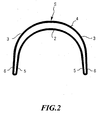
- the wing 3 creates an outer U-profile 4, which around the inner U-profile 2 is arranged around.
- Both U profiles have circular arc segments of different diameters, with the centers of the circular arc segments are offset from one another so that the two profiles are nested one inside the other and the free ends of the U-legs 5 or run asymptotically towards one another.
Landscapes
- Engineering & Computer Science (AREA)
- Mechanical Engineering (AREA)
- Vehicle Body Suspensions (AREA)
- Springs (AREA)
- Butt Welding And Welding Of Specific Article (AREA)
- Nonmetallic Welding Materials (AREA)
- Forging (AREA)
- Pressure Welding/Diffusion-Bonding (AREA)
Abstract
Description
- Fig. 1 a-d
- die verschiedenen Schritte zum Herstellen der Fahrzeugachse ausgehend von einem Metallband, und
- Fig. 2
- eine Querschnittsansicht durch ein fertiges Fahrzeugachsenprofil.
Claims (5)
- Verfahren zum Herstellen einer im Querschnitt im Wesentlichen U-förmigen Fahrzeugachse durch Walzen eines flachen Metallbandes (1), dadurch gekennzeichnet, dass das Metallband (1) zunächst im mittleren Bereich zur Bildung eines inneren
U-Profils (2) U-förmig gewalzt wird, wobei an den freien Enden der U-Schenkel (5) seitlich Flügel (3) stehen bleiben, deren Länge I größer ist als die halbe Abwicklung des inneren U-Profils (2), wonach dann die Flügel in einem weiteren Walzvorgang unter Bildung eines Hohlraumes zum inneren U-Profil (2) zu einem äußeren U-Profil gefaltet und an ihren Stoßkanten miteinander verschweißt werden. - Verfahren nach Anspruch 1, dadurch gekennzeichnet, dass die Stoßkanten durch Ultraschallschweißen miteinander verbunden werden.
- Verfahren nach Anspruch 1 oder 2, dadurch gekennzeichnet, dass die Schweißnaht anschließend gehobelt wird.
- Fahrzeugachse, hergestellt nach dem Verfahren nach einem der Ansprüche 1 bis 3, dadurch gekennzeichnet, dass das innere und das äußere U-Profil (2, 4) im Wesentlichen durch zwei Kreisbogensegmente unterschiedlichen Durchmessers und versetzten Mittelpunktes gebildet werden, wobei die freien Enden (5 bzw. 6) im Wesentlichen asymptotisch aufeinander zu laufen.
- Fahrzeugachse nach dem Anspruch 4, dadurch gekennzeichnet, dass der Abstand zwischen dem inneren und dem äußeren U-Profil (2, 3) im Scheitelpunkt (S) des Achsenquerschnitts ein Vielfaches der Wandstärke des Metallbandes (1) beträgt.
Priority Applications (1)
| Application Number | Priority Date | Filing Date | Title |
|---|---|---|---|
| SI200331515T SI1350580T1 (sl) | 2002-04-05 | 2003-03-28 | Postopek za izdelavo osi vozila s preäśnim presekom v obliki äśrke u |
Applications Claiming Priority (2)
| Application Number | Priority Date | Filing Date | Title |
|---|---|---|---|
| DE10215098A DE10215098A1 (de) | 2002-04-05 | 2002-04-05 | Verfahren zum Herstellen einer im Querschnitt im wesentlichen U-förmigen Fahrzeugachse |
| DE10215098 | 2002-04-05 |
Publications (3)
| Publication Number | Publication Date |
|---|---|
| EP1350580A2 true EP1350580A2 (de) | 2003-10-08 |
| EP1350580A3 EP1350580A3 (de) | 2004-06-09 |
| EP1350580B1 EP1350580B1 (de) | 2009-01-14 |
Family
ID=27816166
Family Applications (1)
| Application Number | Title | Priority Date | Filing Date |
|---|---|---|---|
| EP03007175A Revoked EP1350580B1 (de) | 2002-04-05 | 2003-03-28 | Verfahren zum Herstellen einer im Querschnitt im Wesentlichen U-förmigen Farhzeugachse |
Country Status (7)
| Country | Link |
|---|---|
| EP (1) | EP1350580B1 (de) |
| AT (1) | ATE420743T1 (de) |
| DE (2) | DE10215098A1 (de) |
| DK (1) | DK1350580T3 (de) |
| ES (1) | ES2319748T3 (de) |
| PT (1) | PT1350580E (de) |
| SI (1) | SI1350580T1 (de) |
Cited By (1)
| Publication number | Priority date | Publication date | Assignee | Title |
|---|---|---|---|---|
| EP2939849A1 (de) * | 2014-04-28 | 2015-11-04 | Benteler Automobiltechnik GmbH | Verbundlenkerachse und verfahren zur herstellung eines torsionsprofils |
Families Citing this family (1)
| Publication number | Priority date | Publication date | Assignee | Title |
|---|---|---|---|---|
| DE102013105324B4 (de) * | 2013-05-23 | 2023-02-23 | Thyssenkrupp Steel Europe Ag | Verfahren zur Herstellung eines Kraftfahrzeugbauteils in Form eines Torsionsprofils |
Family Cites Families (7)
| Publication number | Priority date | Publication date | Assignee | Title |
|---|---|---|---|---|
| GB412173A (en) * | 1932-12-14 | 1934-06-14 | Samuel Whyte | Improvements relating to case-hardening |
| DE19653959C1 (de) * | 1996-12-21 | 1998-02-05 | Benteler Werke Ag | Querträger und Verfahren zum Herstellen eines Querträgers |
| DE19846399A1 (de) * | 1998-10-08 | 2000-04-13 | Volkswagen Ag | Verbundlenker-Hinterachse |
| DE19910575A1 (de) * | 1999-03-10 | 2000-09-14 | Volkswagen Ag | Verbundlenkerachse |
| DE19911282A1 (de) * | 1999-03-13 | 2000-09-21 | Thyssen Krupp Automotive Gmbh | Verbundlenkerhinterachse |
| DE19941993C1 (de) * | 1999-09-02 | 2000-12-14 | Benteler Werke Ag | Verfahren zur Herstellung eines biegesteifen torsionsweichen Rohrprofils als Querträger für eine Verbundlenkerhinterachse eines Personenkraftwagens |
| DE10007192C2 (de) * | 2000-02-17 | 2002-10-24 | Benteler Werke Ag | Lenker für Kraftfahrzeuge |
-
2002
- 2002-04-05 DE DE10215098A patent/DE10215098A1/de not_active Ceased
-
2003
- 2003-03-28 DK DK03007175T patent/DK1350580T3/da active
- 2003-03-28 SI SI200331515T patent/SI1350580T1/sl unknown
- 2003-03-28 DE DE50311075T patent/DE50311075D1/de not_active Expired - Fee Related
- 2003-03-28 AT AT03007175T patent/ATE420743T1/de not_active IP Right Cessation
- 2003-03-28 PT PT03007175T patent/PT1350580E/pt unknown
- 2003-03-28 ES ES03007175T patent/ES2319748T3/es not_active Expired - Lifetime
- 2003-03-28 EP EP03007175A patent/EP1350580B1/de not_active Revoked
Non-Patent Citations (1)
| Title |
|---|
| None |
Cited By (1)
| Publication number | Priority date | Publication date | Assignee | Title |
|---|---|---|---|---|
| EP2939849A1 (de) * | 2014-04-28 | 2015-11-04 | Benteler Automobiltechnik GmbH | Verbundlenkerachse und verfahren zur herstellung eines torsionsprofils |
Also Published As
| Publication number | Publication date |
|---|---|
| PT1350580E (pt) | 2009-03-12 |
| DE10215098A1 (de) | 2003-10-23 |
| EP1350580A3 (de) | 2004-06-09 |
| DE50311075D1 (de) | 2009-03-05 |
| EP1350580B1 (de) | 2009-01-14 |
| DK1350580T3 (da) | 2009-03-16 |
| ATE420743T1 (de) | 2009-01-15 |
| ES2319748T3 (es) | 2009-05-12 |
| SI1350580T1 (sl) | 2009-04-30 |
Similar Documents
| Publication | Publication Date | Title |
|---|---|---|
| EP0788849B1 (de) | Verfahren zur Herstellung von Rohren mit Abschnitten unterschiedlicher Wanddicke | |
| DE3220029C2 (de) | ||
| DE60101789T2 (de) | Verfahren zur herstellung eines rohrförmigen bauteils | |
| DE1452122B1 (de) | Verfahren zum Herstellen beispielsweise U-,Winkel-,Rinnen-,Rohr- oder ähnliche Formen aufweisender,hochfester,dehnungsarmer Blechprofile und Einrichtung zur Durchführung des Verfahrens | |
| EP1648631A1 (de) | Verfahren zum herstellen eines längsgeschlitzten hohlprofils mit mehreren, im querschnitt verschiedenen längsabschnitten aus einer ebenen blechplatine | |
| DE2813635C2 (de) | Verfahren und Einrichtung zur Herstellung von Profilen, Hohlkörpern u.dgl. aus mehreren metallenen Streifen konstanter Dicke | |
| DE4333500C2 (de) | Verfahren zur Herstellung eines im Querschnitt gestuften Bleches mit unterschiedlichen Wandstärken sowie Verwendung eines Paares stranggepreßter Profile | |
| DE102007007810A1 (de) | Verfahren zum Formen einer komplex gestalteten Rohrstruktur | |
| DE102009031981B4 (de) | Verfahren zur Herstellung eines Kraftfahrzeugbauteils in Form eines Torsionsprofils | |
| DE3733058A1 (de) | Verfahren zur herstellung duennwandiger metallrohre | |
| DE102012221971A1 (de) | Fahrzeugachse | |
| EP1479458B1 (de) | Verfahren zum Herstellen von Rohren und Profilen | |
| DE2624872C3 (de) | Verfahren zum Herstellen von ungeteilten Felgen | |
| EP0031822B1 (de) | Verfahren zum biegen von blechen und vorrichtung zur durchführung des verfahrens | |
| DE102011120890A1 (de) | Verfahren zur Herstellung eines mehrschichtigen Metallrohres und danach hergestelltes mehrschichtiges Metallrohr | |
| DE102008056521B3 (de) | Verfahren zum Herstellen einer grobstrukturierten Materialbahn mit feinstrukturierten Teilflächen und durchgängigen, ebenen oder nahezu ebenen Rändern, ein nach dem Verfahren hergestelltes Erzeugnis sowie bevorzugte Verwendungen | |
| DE102007056645B4 (de) | Schweller eines Kraftfahrzeugs und Kraftfahrzeug | |
| DE3125634A1 (de) | Verfahren zum formen eines metallrads | |
| EP1000677B1 (de) | Verfahren zur Herstellung eines Bauteils mittels Innenhochdruck-Umformen | |
| EP1350580B1 (de) | Verfahren zum Herstellen einer im Querschnitt im Wesentlichen U-förmigen Farhzeugachse | |
| DE10102759A1 (de) | Verbundlenkerhinterachse | |
| EP1464566B1 (de) | Verfahren zur Herstellung eines Hohlformteils mit geschlossenem Querschnitt und einer Verstärkung | |
| DD276043A1 (de) | Verfahren und vorrichtung zur herstellung duennwandiger rohre | |
| DE102007002450B3 (de) | Verbundlenkerachse für Kraftfahrzeuge und Verfahren zur Herstellung eines Torsionsprofils für eine Verbundlenkerachse | |
| DE19548224A1 (de) | Verfahren zur Herstellung eines Rohrteiles, insbesondere einer Krümmer-Rohrabzweigung einer Kraftfahrzeug-Abgasanlage, sowie eine hiernach gefertigte Krümmer-Rohrabzweigung |
Legal Events
| Date | Code | Title | Description |
|---|---|---|---|
| PUAI | Public reference made under article 153(3) epc to a published international application that has entered the european phase |
Free format text: ORIGINAL CODE: 0009012 |
|
| AK | Designated contracting states |
Kind code of ref document: A2 Designated state(s): AT BE BG CH CY CZ DE DK EE ES FI FR GB GR HU IE IT LI LU MC NL PT RO SE SI SK TR |
|
| AX | Request for extension of the european patent |
Extension state: AL LT LV MK |
|
| PUAL | Search report despatched |
Free format text: ORIGINAL CODE: 0009013 |
|
| AK | Designated contracting states |
Kind code of ref document: A3 Designated state(s): AT BE BG CH CY CZ DE DK EE ES FI FR GB GR HU IE IT LI LU MC NL PT RO SE SI SK TR |
|
| AX | Request for extension of the european patent |
Extension state: AL LT LV MK |
|
| 17P | Request for examination filed |
Effective date: 20041207 |
|
| AKX | Designation fees paid |
Designated state(s): AT BE BG CH CY CZ DE DK EE ES FI FR GB GR HU IE IT LI LU MC NL PT RO SE SI SK TR |
|
| GRAP | Despatch of communication of intention to grant a patent |
Free format text: ORIGINAL CODE: EPIDOSNIGR1 |
|
| GRAS | Grant fee paid |
Free format text: ORIGINAL CODE: EPIDOSNIGR3 |
|
| GRAA | (expected) grant |
Free format text: ORIGINAL CODE: 0009210 |
|
| AK | Designated contracting states |
Kind code of ref document: B1 Designated state(s): AT BE BG CH CY CZ DE DK EE ES FI FR GB GR HU IE IT LI LU MC NL PT RO SE SI SK TR |
|
| REG | Reference to a national code |
Ref country code: GB Ref legal event code: FG4D Free format text: NOT ENGLISH |
|
| REG | Reference to a national code |
Ref country code: CH Ref legal event code: EP |
|
| REG | Reference to a national code |
Ref country code: CH Ref legal event code: NV Representative=s name: BOVARD AG PATENTANWAELTE |
|
| REG | Reference to a national code |
Ref country code: IE Ref legal event code: FG4D Free format text: LANGUAGE OF EP DOCUMENT: GERMAN |
|
| REF | Corresponds to: |
Ref document number: 50311075 Country of ref document: DE Date of ref document: 20090305 Kind code of ref document: P |
|
| REG | Reference to a national code |
Ref country code: PT Ref legal event code: SC4A Free format text: AVAILABILITY OF NATIONAL TRANSLATION Effective date: 20090303 |
|
| REG | Reference to a national code |
Ref country code: DK Ref legal event code: T3 |
|
| REG | Reference to a national code |
Ref country code: GR Ref legal event code: EP Ref document number: 20090400546 Country of ref document: GR |
|
| REG | Reference to a national code |
Ref country code: RO Ref legal event code: EPE |
|
| REG | Reference to a national code |
Ref country code: SE Ref legal event code: TRGR |
|
| PGFP | Annual fee paid to national office [announced via postgrant information from national office to epo] |
Ref country code: AT Payment date: 20090324 Year of fee payment: 7 Ref country code: DK Payment date: 20090326 Year of fee payment: 7 Ref country code: EE Payment date: 20090223 Year of fee payment: 7 Ref country code: ES Payment date: 20090317 Year of fee payment: 7 Ref country code: IE Payment date: 20090324 Year of fee payment: 7 Ref country code: LU Payment date: 20090330 Year of fee payment: 7 |
|
| REG | Reference to a national code |
Ref country code: ES Ref legal event code: FG2A Ref document number: 2319748 Country of ref document: ES Kind code of ref document: T3 |
|
| PGFP | Annual fee paid to national office [announced via postgrant information from national office to epo] |
Ref country code: CZ Payment date: 20090304 Year of fee payment: 7 Ref country code: FI Payment date: 20090325 Year of fee payment: 7 Ref country code: NL Payment date: 20090327 Year of fee payment: 7 Ref country code: PT Payment date: 20090310 Year of fee payment: 7 Ref country code: RO Payment date: 20090302 Year of fee payment: 7 Ref country code: SI Payment date: 20090225 Year of fee payment: 7 |
|
| PGFP | Annual fee paid to national office [announced via postgrant information from national office to epo] |
Ref country code: CH Payment date: 20090326 Year of fee payment: 7 Ref country code: GB Payment date: 20090324 Year of fee payment: 7 Ref country code: GR Payment date: 20090330 Year of fee payment: 7 |
|
| REG | Reference to a national code |
Ref country code: HU Ref legal event code: AG4A Ref document number: E005184 Country of ref document: HU |
|
| PGFP | Annual fee paid to national office [announced via postgrant information from national office to epo] |
Ref country code: BE Payment date: 20090326 Year of fee payment: 7 Ref country code: BG Payment date: 20090331 Year of fee payment: 7 |
|
| PGFP | Annual fee paid to national office [announced via postgrant information from national office to epo] |
Ref country code: DE Payment date: 20090429 Year of fee payment: 7 Ref country code: IT Payment date: 20090320 Year of fee payment: 7 Ref country code: SE Payment date: 20090324 Year of fee payment: 7 |
|
| PGFP | Annual fee paid to national office [announced via postgrant information from national office to epo] |
Ref country code: SK Payment date: 20090302 Year of fee payment: 7 |
|
| PLBI | Opposition filed |
Free format text: ORIGINAL CODE: 0009260 |
|
| PG25 | Lapsed in a contracting state [announced via postgrant information from national office to epo] |
Ref country code: MC Free format text: LAPSE BECAUSE OF NON-PAYMENT OF DUE FEES Effective date: 20090331 |
|
| PGFP | Annual fee paid to national office [announced via postgrant information from national office to epo] |
Ref country code: FR Payment date: 20090325 Year of fee payment: 7 |
|
| 26 | Opposition filed |
Opponent name: THYSSENKRUPP UMFORMTECHNIK GMBH Effective date: 20090929 |
|
| PLAX | Notice of opposition and request to file observation + time limit sent |
Free format text: ORIGINAL CODE: EPIDOSNOBS2 |
|
| PGFP | Annual fee paid to national office [announced via postgrant information from national office to epo] |
Ref country code: HU Payment date: 20090309 Year of fee payment: 7 |
|
| NLR1 | Nl: opposition has been filed with the epo |
Opponent name: THYSSENKRUPP UMFORMTECHNIK GMBH |
|
| RDAF | Communication despatched that patent is revoked |
Free format text: ORIGINAL CODE: EPIDOSNREV1 |
|
| REG | Reference to a national code |
Ref country code: NL Ref legal event code: V1 Effective date: 20101001 |
|
| REG | Reference to a national code |
Ref country code: CH Ref legal event code: PL |
|
| EUG | Se: european patent has lapsed | ||
| REG | Reference to a national code |
Ref country code: DK Ref legal event code: EBP |
|
| GBPC | Gb: european patent ceased through non-payment of renewal fee |
Effective date: 20100328 |
|
| PG25 | Lapsed in a contracting state [announced via postgrant information from national office to epo] |
Ref country code: AT Free format text: LAPSE BECAUSE OF NON-PAYMENT OF DUE FEES Effective date: 20100328 Ref country code: FI Free format text: LAPSE BECAUSE OF NON-PAYMENT OF DUE FEES Effective date: 20100328 |
|
| REG | Reference to a national code |
Ref country code: SK Ref legal event code: MM4A Ref document number: E 5176 Country of ref document: SK Effective date: 20100328 |
|
| REG | Reference to a national code |
Ref country code: EE Ref legal event code: MM4A Ref document number: E002885 Country of ref document: EE Effective date: 20100331 |
|
| REG | Reference to a national code |
Ref country code: IE Ref legal event code: MM4A |
|
| REG | Reference to a national code |
Ref country code: FR Ref legal event code: ST Effective date: 20101130 |
|
| REG | Reference to a national code |
Ref country code: SI Ref legal event code: KO00 Effective date: 20101112 |
|
| RDAG | Patent revoked |
Free format text: ORIGINAL CODE: 0009271 |
|
| STAA | Information on the status of an ep patent application or granted ep patent |
Free format text: STATUS: PATENT REVOKED |
|
| PG25 | Lapsed in a contracting state [announced via postgrant information from national office to epo] |
Ref country code: IE Free format text: LAPSE BECAUSE OF NON-PAYMENT OF DUE FEES Effective date: 20100329 Ref country code: FR Free format text: LAPSE BECAUSE OF NON-PAYMENT OF DUE FEES Effective date: 20100331 Ref country code: EE Free format text: LAPSE BECAUSE OF NON-PAYMENT OF DUE FEES Effective date: 20100331 |
|
| 27W | Patent revoked |
Effective date: 20100918 |
|
| REG | Reference to a national code |
Ref country code: PT Ref legal event code: MP4A Effective date: 20110209 |
|
| PG25 | Lapsed in a contracting state [announced via postgrant information from national office to epo] |
Ref country code: SK Free format text: LAPSE BECAUSE OF NON-PAYMENT OF DUE FEES Effective date: 20100328 Ref country code: SI Free format text: LAPSE BECAUSE OF NON-PAYMENT OF DUE FEES Effective date: 20100329 Ref country code: CH Free format text: LAPSE BECAUSE OF NON-PAYMENT OF DUE FEES Effective date: 20100331 Ref country code: CZ Free format text: LAPSE BECAUSE OF NON-PAYMENT OF DUE FEES Effective date: 20100328 Ref country code: HU Free format text: LAPSE BECAUSE OF NON-PAYMENT OF DUE FEES Effective date: 20100329 Ref country code: LI Free format text: LAPSE BECAUSE OF NON-PAYMENT OF DUE FEES Effective date: 20100331 |
|
| PG25 | Lapsed in a contracting state [announced via postgrant information from national office to epo] |
Ref country code: GB Free format text: LAPSE BECAUSE OF NON-PAYMENT OF DUE FEES Effective date: 20100328 Ref country code: IT Free format text: LAPSE BECAUSE OF NON-PAYMENT OF DUE FEES Effective date: 20100328 |
|
| PG25 | Lapsed in a contracting state [announced via postgrant information from national office to epo] |
Ref country code: DK Free format text: LAPSE BECAUSE OF NON-PAYMENT OF DUE FEES Effective date: 20100331 |
|
| PG25 | Lapsed in a contracting state [announced via postgrant information from national office to epo] |
Ref country code: RO Free format text: LAPSE BECAUSE OF NON-PAYMENT OF DUE FEES Effective date: 20100328 |
|
| PG25 | Lapsed in a contracting state [announced via postgrant information from national office to epo] |
Ref country code: CY Free format text: LAPSE BECAUSE OF FAILURE TO SUBMIT A TRANSLATION OF THE DESCRIPTION OR TO PAY THE FEE WITHIN THE PRESCRIBED TIME-LIMIT Effective date: 20090114 |
|
| PGFP | Annual fee paid to national office [announced via postgrant information from national office to epo] |
Ref country code: TR Payment date: 20090330 Year of fee payment: 7 |
|
| PG25 | Lapsed in a contracting state [announced via postgrant information from national office to epo] |
Ref country code: SE Free format text: LAPSE BECAUSE OF NON-PAYMENT OF DUE FEES Effective date: 20100329 |
|
| REG | Reference to a national code |
Ref country code: SE Ref legal event code: ECNC |
|
| PG25 | Lapsed in a contracting state [announced via postgrant information from national office to epo] |
Ref country code: ES Free format text: LAPSE BECAUSE OF NON-PAYMENT OF DUE FEES Effective date: 20100329 |