EP1350486A1 - Endoprothese - Google Patents
Endoprothese Download PDFInfo
- Publication number
- EP1350486A1 EP1350486A1 EP03006677A EP03006677A EP1350486A1 EP 1350486 A1 EP1350486 A1 EP 1350486A1 EP 03006677 A EP03006677 A EP 03006677A EP 03006677 A EP03006677 A EP 03006677A EP 1350486 A1 EP1350486 A1 EP 1350486A1
- Authority
- EP
- European Patent Office
- Prior art keywords
- projection
- receiving opening
- recess
- insertion end
- kit
- Prior art date
- Legal status (The legal status is an assumption and is not a legal conclusion. Google has not performed a legal analysis and makes no representation as to the accuracy of the status listed.)
- Withdrawn
Links
Images


Classifications
-
- A—HUMAN NECESSITIES
- A61—MEDICAL OR VETERINARY SCIENCE; HYGIENE
- A61F—FILTERS IMPLANTABLE INTO BLOOD VESSELS; PROSTHESES; DEVICES PROVIDING PATENCY TO, OR PREVENTING COLLAPSING OF, TUBULAR STRUCTURES OF THE BODY, e.g. STENTS; ORTHOPAEDIC, NURSING OR CONTRACEPTIVE DEVICES; FOMENTATION; TREATMENT OR PROTECTION OF EYES OR EARS; BANDAGES, DRESSINGS OR ABSORBENT PADS; FIRST-AID KITS
- A61F2/00—Filters implantable into blood vessels; Prostheses, i.e. artificial substitutes or replacements for parts of the body; Appliances for connecting them with the body; Devices providing patency to, or preventing collapsing of, tubular structures of the body, e.g. stents
- A61F2/02—Prostheses implantable into the body
- A61F2/30—Joints
- A61F2/32—Joints for the hip
- A61F2/36—Femoral heads ; Femoral endoprostheses
- A61F2/3609—Femoral heads or necks; Connections of endoprosthetic heads or necks to endoprosthetic femoral shafts
-
- A—HUMAN NECESSITIES
- A61—MEDICAL OR VETERINARY SCIENCE; HYGIENE
- A61F—FILTERS IMPLANTABLE INTO BLOOD VESSELS; PROSTHESES; DEVICES PROVIDING PATENCY TO, OR PREVENTING COLLAPSING OF, TUBULAR STRUCTURES OF THE BODY, e.g. STENTS; ORTHOPAEDIC, NURSING OR CONTRACEPTIVE DEVICES; FOMENTATION; TREATMENT OR PROTECTION OF EYES OR EARS; BANDAGES, DRESSINGS OR ABSORBENT PADS; FIRST-AID KITS
- A61F2/00—Filters implantable into blood vessels; Prostheses, i.e. artificial substitutes or replacements for parts of the body; Appliances for connecting them with the body; Devices providing patency to, or preventing collapsing of, tubular structures of the body, e.g. stents
- A61F2/02—Prostheses implantable into the body
- A61F2/30—Joints
- A61F2/32—Joints for the hip
- A61F2/36—Femoral heads ; Femoral endoprostheses
- A61F2/3662—Femoral shafts
- A61F2/367—Proximal or metaphyseal parts of shafts
-
- A—HUMAN NECESSITIES
- A61—MEDICAL OR VETERINARY SCIENCE; HYGIENE
- A61F—FILTERS IMPLANTABLE INTO BLOOD VESSELS; PROSTHESES; DEVICES PROVIDING PATENCY TO, OR PREVENTING COLLAPSING OF, TUBULAR STRUCTURES OF THE BODY, e.g. STENTS; ORTHOPAEDIC, NURSING OR CONTRACEPTIVE DEVICES; FOMENTATION; TREATMENT OR PROTECTION OF EYES OR EARS; BANDAGES, DRESSINGS OR ABSORBENT PADS; FIRST-AID KITS
- A61F2/00—Filters implantable into blood vessels; Prostheses, i.e. artificial substitutes or replacements for parts of the body; Appliances for connecting them with the body; Devices providing patency to, or preventing collapsing of, tubular structures of the body, e.g. stents
- A61F2/02—Prostheses implantable into the body
- A61F2/30—Joints
- A61F2002/30001—Additional features of subject-matter classified in A61F2/28, A61F2/30 and subgroups thereof
- A61F2002/30108—Shapes
- A61F2002/3011—Cross-sections or two-dimensional shapes
- A61F2002/30182—Other shapes
- A61F2002/30187—D-shaped or half-disc-shaped
-
- A—HUMAN NECESSITIES
- A61—MEDICAL OR VETERINARY SCIENCE; HYGIENE
- A61F—FILTERS IMPLANTABLE INTO BLOOD VESSELS; PROSTHESES; DEVICES PROVIDING PATENCY TO, OR PREVENTING COLLAPSING OF, TUBULAR STRUCTURES OF THE BODY, e.g. STENTS; ORTHOPAEDIC, NURSING OR CONTRACEPTIVE DEVICES; FOMENTATION; TREATMENT OR PROTECTION OF EYES OR EARS; BANDAGES, DRESSINGS OR ABSORBENT PADS; FIRST-AID KITS
- A61F2/00—Filters implantable into blood vessels; Prostheses, i.e. artificial substitutes or replacements for parts of the body; Appliances for connecting them with the body; Devices providing patency to, or preventing collapsing of, tubular structures of the body, e.g. stents
- A61F2/02—Prostheses implantable into the body
- A61F2/30—Joints
- A61F2002/30001—Additional features of subject-matter classified in A61F2/28, A61F2/30 and subgroups thereof
- A61F2002/30316—The prosthesis having different structural features at different locations within the same prosthesis; Connections between prosthetic parts; Special structural features of bone or joint prostheses not otherwise provided for
- A61F2002/30329—Connections or couplings between prosthetic parts, e.g. between modular parts; Connecting elements
- A61F2002/30331—Connections or couplings between prosthetic parts, e.g. between modular parts; Connecting elements made by longitudinally pushing a protrusion into a complementarily-shaped recess, e.g. held by friction fit
-
- A—HUMAN NECESSITIES
- A61—MEDICAL OR VETERINARY SCIENCE; HYGIENE
- A61F—FILTERS IMPLANTABLE INTO BLOOD VESSELS; PROSTHESES; DEVICES PROVIDING PATENCY TO, OR PREVENTING COLLAPSING OF, TUBULAR STRUCTURES OF THE BODY, e.g. STENTS; ORTHOPAEDIC, NURSING OR CONTRACEPTIVE DEVICES; FOMENTATION; TREATMENT OR PROTECTION OF EYES OR EARS; BANDAGES, DRESSINGS OR ABSORBENT PADS; FIRST-AID KITS
- A61F2/00—Filters implantable into blood vessels; Prostheses, i.e. artificial substitutes or replacements for parts of the body; Appliances for connecting them with the body; Devices providing patency to, or preventing collapsing of, tubular structures of the body, e.g. stents
- A61F2/02—Prostheses implantable into the body
- A61F2/30—Joints
- A61F2002/30001—Additional features of subject-matter classified in A61F2/28, A61F2/30 and subgroups thereof
- A61F2002/30316—The prosthesis having different structural features at different locations within the same prosthesis; Connections between prosthetic parts; Special structural features of bone or joint prostheses not otherwise provided for
- A61F2002/30329—Connections or couplings between prosthetic parts, e.g. between modular parts; Connecting elements
- A61F2002/30331—Connections or couplings between prosthetic parts, e.g. between modular parts; Connecting elements made by longitudinally pushing a protrusion into a complementarily-shaped recess, e.g. held by friction fit
- A61F2002/30332—Conically- or frustoconically-shaped protrusion and recess
-
- A—HUMAN NECESSITIES
- A61—MEDICAL OR VETERINARY SCIENCE; HYGIENE
- A61F—FILTERS IMPLANTABLE INTO BLOOD VESSELS; PROSTHESES; DEVICES PROVIDING PATENCY TO, OR PREVENTING COLLAPSING OF, TUBULAR STRUCTURES OF THE BODY, e.g. STENTS; ORTHOPAEDIC, NURSING OR CONTRACEPTIVE DEVICES; FOMENTATION; TREATMENT OR PROTECTION OF EYES OR EARS; BANDAGES, DRESSINGS OR ABSORBENT PADS; FIRST-AID KITS
- A61F2/00—Filters implantable into blood vessels; Prostheses, i.e. artificial substitutes or replacements for parts of the body; Appliances for connecting them with the body; Devices providing patency to, or preventing collapsing of, tubular structures of the body, e.g. stents
- A61F2/02—Prostheses implantable into the body
- A61F2/30—Joints
- A61F2002/30001—Additional features of subject-matter classified in A61F2/28, A61F2/30 and subgroups thereof
- A61F2002/30316—The prosthesis having different structural features at different locations within the same prosthesis; Connections between prosthetic parts; Special structural features of bone or joint prostheses not otherwise provided for
- A61F2002/30329—Connections or couplings between prosthetic parts, e.g. between modular parts; Connecting elements
- A61F2002/30331—Connections or couplings between prosthetic parts, e.g. between modular parts; Connecting elements made by longitudinally pushing a protrusion into a complementarily-shaped recess, e.g. held by friction fit
- A61F2002/30332—Conically- or frustoconically-shaped protrusion and recess
- A61F2002/30334—Cone of elliptical or oval basis
-
- A—HUMAN NECESSITIES
- A61—MEDICAL OR VETERINARY SCIENCE; HYGIENE
- A61F—FILTERS IMPLANTABLE INTO BLOOD VESSELS; PROSTHESES; DEVICES PROVIDING PATENCY TO, OR PREVENTING COLLAPSING OF, TUBULAR STRUCTURES OF THE BODY, e.g. STENTS; ORTHOPAEDIC, NURSING OR CONTRACEPTIVE DEVICES; FOMENTATION; TREATMENT OR PROTECTION OF EYES OR EARS; BANDAGES, DRESSINGS OR ABSORBENT PADS; FIRST-AID KITS
- A61F2/00—Filters implantable into blood vessels; Prostheses, i.e. artificial substitutes or replacements for parts of the body; Appliances for connecting them with the body; Devices providing patency to, or preventing collapsing of, tubular structures of the body, e.g. stents
- A61F2/02—Prostheses implantable into the body
- A61F2/30—Joints
- A61F2002/30001—Additional features of subject-matter classified in A61F2/28, A61F2/30 and subgroups thereof
- A61F2002/30316—The prosthesis having different structural features at different locations within the same prosthesis; Connections between prosthetic parts; Special structural features of bone or joint prostheses not otherwise provided for
- A61F2002/30329—Connections or couplings between prosthetic parts, e.g. between modular parts; Connecting elements
- A61F2002/30331—Connections or couplings between prosthetic parts, e.g. between modular parts; Connecting elements made by longitudinally pushing a protrusion into a complementarily-shaped recess, e.g. held by friction fit
- A61F2002/30332—Conically- or frustoconically-shaped protrusion and recess
- A61F2002/30339—Double cones, i.e. connecting element having two conical connections, one at each of its opposite ends
-
- A—HUMAN NECESSITIES
- A61—MEDICAL OR VETERINARY SCIENCE; HYGIENE
- A61F—FILTERS IMPLANTABLE INTO BLOOD VESSELS; PROSTHESES; DEVICES PROVIDING PATENCY TO, OR PREVENTING COLLAPSING OF, TUBULAR STRUCTURES OF THE BODY, e.g. STENTS; ORTHOPAEDIC, NURSING OR CONTRACEPTIVE DEVICES; FOMENTATION; TREATMENT OR PROTECTION OF EYES OR EARS; BANDAGES, DRESSINGS OR ABSORBENT PADS; FIRST-AID KITS
- A61F2/00—Filters implantable into blood vessels; Prostheses, i.e. artificial substitutes or replacements for parts of the body; Appliances for connecting them with the body; Devices providing patency to, or preventing collapsing of, tubular structures of the body, e.g. stents
- A61F2/02—Prostheses implantable into the body
- A61F2/30—Joints
- A61F2002/30001—Additional features of subject-matter classified in A61F2/28, A61F2/30 and subgroups thereof
- A61F2002/30316—The prosthesis having different structural features at different locations within the same prosthesis; Connections between prosthetic parts; Special structural features of bone or joint prostheses not otherwise provided for
- A61F2002/30329—Connections or couplings between prosthetic parts, e.g. between modular parts; Connecting elements
- A61F2002/30331—Connections or couplings between prosthetic parts, e.g. between modular parts; Connecting elements made by longitudinally pushing a protrusion into a complementarily-shaped recess, e.g. held by friction fit
- A61F2002/30354—Cylindrically-shaped protrusion and recess, e.g. cylinder of circular basis
-
- A—HUMAN NECESSITIES
- A61—MEDICAL OR VETERINARY SCIENCE; HYGIENE
- A61F—FILTERS IMPLANTABLE INTO BLOOD VESSELS; PROSTHESES; DEVICES PROVIDING PATENCY TO, OR PREVENTING COLLAPSING OF, TUBULAR STRUCTURES OF THE BODY, e.g. STENTS; ORTHOPAEDIC, NURSING OR CONTRACEPTIVE DEVICES; FOMENTATION; TREATMENT OR PROTECTION OF EYES OR EARS; BANDAGES, DRESSINGS OR ABSORBENT PADS; FIRST-AID KITS
- A61F2/00—Filters implantable into blood vessels; Prostheses, i.e. artificial substitutes or replacements for parts of the body; Appliances for connecting them with the body; Devices providing patency to, or preventing collapsing of, tubular structures of the body, e.g. stents
- A61F2/02—Prostheses implantable into the body
- A61F2/30—Joints
- A61F2002/30001—Additional features of subject-matter classified in A61F2/28, A61F2/30 and subgroups thereof
- A61F2002/30316—The prosthesis having different structural features at different locations within the same prosthesis; Connections between prosthetic parts; Special structural features of bone or joint prostheses not otherwise provided for
- A61F2002/30329—Connections or couplings between prosthetic parts, e.g. between modular parts; Connecting elements
- A61F2002/3053—Connections or couplings between prosthetic parts, e.g. between modular parts; Connecting elements having additional means for preventing unwanted connections
-
- A—HUMAN NECESSITIES
- A61—MEDICAL OR VETERINARY SCIENCE; HYGIENE
- A61F—FILTERS IMPLANTABLE INTO BLOOD VESSELS; PROSTHESES; DEVICES PROVIDING PATENCY TO, OR PREVENTING COLLAPSING OF, TUBULAR STRUCTURES OF THE BODY, e.g. STENTS; ORTHOPAEDIC, NURSING OR CONTRACEPTIVE DEVICES; FOMENTATION; TREATMENT OR PROTECTION OF EYES OR EARS; BANDAGES, DRESSINGS OR ABSORBENT PADS; FIRST-AID KITS
- A61F2/00—Filters implantable into blood vessels; Prostheses, i.e. artificial substitutes or replacements for parts of the body; Appliances for connecting them with the body; Devices providing patency to, or preventing collapsing of, tubular structures of the body, e.g. stents
- A61F2/02—Prostheses implantable into the body
- A61F2/30—Joints
- A61F2002/30001—Additional features of subject-matter classified in A61F2/28, A61F2/30 and subgroups thereof
- A61F2002/30316—The prosthesis having different structural features at different locations within the same prosthesis; Connections between prosthetic parts; Special structural features of bone or joint prostheses not otherwise provided for
- A61F2002/30535—Special structural features of bone or joint prostheses not otherwise provided for
- A61F2002/30604—Special structural features of bone or joint prostheses not otherwise provided for modular
-
- A—HUMAN NECESSITIES
- A61—MEDICAL OR VETERINARY SCIENCE; HYGIENE
- A61F—FILTERS IMPLANTABLE INTO BLOOD VESSELS; PROSTHESES; DEVICES PROVIDING PATENCY TO, OR PREVENTING COLLAPSING OF, TUBULAR STRUCTURES OF THE BODY, e.g. STENTS; ORTHOPAEDIC, NURSING OR CONTRACEPTIVE DEVICES; FOMENTATION; TREATMENT OR PROTECTION OF EYES OR EARS; BANDAGES, DRESSINGS OR ABSORBENT PADS; FIRST-AID KITS
- A61F2/00—Filters implantable into blood vessels; Prostheses, i.e. artificial substitutes or replacements for parts of the body; Appliances for connecting them with the body; Devices providing patency to, or preventing collapsing of, tubular structures of the body, e.g. stents
- A61F2/02—Prostheses implantable into the body
- A61F2/30—Joints
- A61F2002/30001—Additional features of subject-matter classified in A61F2/28, A61F2/30 and subgroups thereof
- A61F2002/30316—The prosthesis having different structural features at different locations within the same prosthesis; Connections between prosthetic parts; Special structural features of bone or joint prostheses not otherwise provided for
- A61F2002/30535—Special structural features of bone or joint prostheses not otherwise provided for
- A61F2002/30604—Special structural features of bone or joint prostheses not otherwise provided for modular
- A61F2002/30607—Kits of prosthetic parts to be assembled in various combinations for forming different prostheses
-
- A—HUMAN NECESSITIES
- A61—MEDICAL OR VETERINARY SCIENCE; HYGIENE
- A61F—FILTERS IMPLANTABLE INTO BLOOD VESSELS; PROSTHESES; DEVICES PROVIDING PATENCY TO, OR PREVENTING COLLAPSING OF, TUBULAR STRUCTURES OF THE BODY, e.g. STENTS; ORTHOPAEDIC, NURSING OR CONTRACEPTIVE DEVICES; FOMENTATION; TREATMENT OR PROTECTION OF EYES OR EARS; BANDAGES, DRESSINGS OR ABSORBENT PADS; FIRST-AID KITS
- A61F2/00—Filters implantable into blood vessels; Prostheses, i.e. artificial substitutes or replacements for parts of the body; Appliances for connecting them with the body; Devices providing patency to, or preventing collapsing of, tubular structures of the body, e.g. stents
- A61F2/02—Prostheses implantable into the body
- A61F2/30—Joints
- A61F2002/30001—Additional features of subject-matter classified in A61F2/28, A61F2/30 and subgroups thereof
- A61F2002/30316—The prosthesis having different structural features at different locations within the same prosthesis; Connections between prosthetic parts; Special structural features of bone or joint prostheses not otherwise provided for
- A61F2002/30535—Special structural features of bone or joint prostheses not otherwise provided for
- A61F2002/30604—Special structural features of bone or joint prostheses not otherwise provided for modular
- A61F2002/30616—Sets comprising a plurality of prosthetic parts of different sizes or orientations
-
- A—HUMAN NECESSITIES
- A61—MEDICAL OR VETERINARY SCIENCE; HYGIENE
- A61F—FILTERS IMPLANTABLE INTO BLOOD VESSELS; PROSTHESES; DEVICES PROVIDING PATENCY TO, OR PREVENTING COLLAPSING OF, TUBULAR STRUCTURES OF THE BODY, e.g. STENTS; ORTHOPAEDIC, NURSING OR CONTRACEPTIVE DEVICES; FOMENTATION; TREATMENT OR PROTECTION OF EYES OR EARS; BANDAGES, DRESSINGS OR ABSORBENT PADS; FIRST-AID KITS
- A61F2/00—Filters implantable into blood vessels; Prostheses, i.e. artificial substitutes or replacements for parts of the body; Appliances for connecting them with the body; Devices providing patency to, or preventing collapsing of, tubular structures of the body, e.g. stents
- A61F2/02—Prostheses implantable into the body
- A61F2/30—Joints
- A61F2/30767—Special external or bone-contacting surface, e.g. coating for improving bone ingrowth
- A61F2/30771—Special external or bone-contacting surface, e.g. coating for improving bone ingrowth applied in original prostheses, e.g. holes or grooves
- A61F2002/30795—Blind bores, e.g. of circular cross-section
- A61F2002/30797—Blind bores, e.g. of circular cross-section internally-threaded
-
- A—HUMAN NECESSITIES
- A61—MEDICAL OR VETERINARY SCIENCE; HYGIENE
- A61F—FILTERS IMPLANTABLE INTO BLOOD VESSELS; PROSTHESES; DEVICES PROVIDING PATENCY TO, OR PREVENTING COLLAPSING OF, TUBULAR STRUCTURES OF THE BODY, e.g. STENTS; ORTHOPAEDIC, NURSING OR CONTRACEPTIVE DEVICES; FOMENTATION; TREATMENT OR PROTECTION OF EYES OR EARS; BANDAGES, DRESSINGS OR ABSORBENT PADS; FIRST-AID KITS
- A61F2/00—Filters implantable into blood vessels; Prostheses, i.e. artificial substitutes or replacements for parts of the body; Appliances for connecting them with the body; Devices providing patency to, or preventing collapsing of, tubular structures of the body, e.g. stents
- A61F2/02—Prostheses implantable into the body
- A61F2/30—Joints
- A61F2/30767—Special external or bone-contacting surface, e.g. coating for improving bone ingrowth
- A61F2/30771—Special external or bone-contacting surface, e.g. coating for improving bone ingrowth applied in original prostheses, e.g. holes or grooves
- A61F2002/30795—Blind bores, e.g. of circular cross-section
- A61F2002/30807—Plurality of blind bores
- A61F2002/30808—Plurality of blind bores parallel
-
- A—HUMAN NECESSITIES
- A61—MEDICAL OR VETERINARY SCIENCE; HYGIENE
- A61F—FILTERS IMPLANTABLE INTO BLOOD VESSELS; PROSTHESES; DEVICES PROVIDING PATENCY TO, OR PREVENTING COLLAPSING OF, TUBULAR STRUCTURES OF THE BODY, e.g. STENTS; ORTHOPAEDIC, NURSING OR CONTRACEPTIVE DEVICES; FOMENTATION; TREATMENT OR PROTECTION OF EYES OR EARS; BANDAGES, DRESSINGS OR ABSORBENT PADS; FIRST-AID KITS
- A61F2/00—Filters implantable into blood vessels; Prostheses, i.e. artificial substitutes or replacements for parts of the body; Appliances for connecting them with the body; Devices providing patency to, or preventing collapsing of, tubular structures of the body, e.g. stents
- A61F2/02—Prostheses implantable into the body
- A61F2/30—Joints
- A61F2/32—Joints for the hip
- A61F2/36—Femoral heads ; Femoral endoprostheses
- A61F2/3609—Femoral heads or necks; Connections of endoprosthetic heads or necks to endoprosthetic femoral shafts
- A61F2002/3625—Necks
-
- A—HUMAN NECESSITIES
- A61—MEDICAL OR VETERINARY SCIENCE; HYGIENE
- A61F—FILTERS IMPLANTABLE INTO BLOOD VESSELS; PROSTHESES; DEVICES PROVIDING PATENCY TO, OR PREVENTING COLLAPSING OF, TUBULAR STRUCTURES OF THE BODY, e.g. STENTS; ORTHOPAEDIC, NURSING OR CONTRACEPTIVE DEVICES; FOMENTATION; TREATMENT OR PROTECTION OF EYES OR EARS; BANDAGES, DRESSINGS OR ABSORBENT PADS; FIRST-AID KITS
- A61F2/00—Filters implantable into blood vessels; Prostheses, i.e. artificial substitutes or replacements for parts of the body; Appliances for connecting them with the body; Devices providing patency to, or preventing collapsing of, tubular structures of the body, e.g. stents
- A61F2/02—Prostheses implantable into the body
- A61F2/30—Joints
- A61F2/32—Joints for the hip
- A61F2/36—Femoral heads ; Femoral endoprostheses
- A61F2/3609—Femoral heads or necks; Connections of endoprosthetic heads or necks to endoprosthetic femoral shafts
- A61F2002/365—Connections of heads to necks
-
- A—HUMAN NECESSITIES
- A61—MEDICAL OR VETERINARY SCIENCE; HYGIENE
- A61F—FILTERS IMPLANTABLE INTO BLOOD VESSELS; PROSTHESES; DEVICES PROVIDING PATENCY TO, OR PREVENTING COLLAPSING OF, TUBULAR STRUCTURES OF THE BODY, e.g. STENTS; ORTHOPAEDIC, NURSING OR CONTRACEPTIVE DEVICES; FOMENTATION; TREATMENT OR PROTECTION OF EYES OR EARS; BANDAGES, DRESSINGS OR ABSORBENT PADS; FIRST-AID KITS
- A61F2/00—Filters implantable into blood vessels; Prostheses, i.e. artificial substitutes or replacements for parts of the body; Appliances for connecting them with the body; Devices providing patency to, or preventing collapsing of, tubular structures of the body, e.g. stents
- A61F2/02—Prostheses implantable into the body
- A61F2/30—Joints
- A61F2/32—Joints for the hip
- A61F2/36—Femoral heads ; Femoral endoprostheses
- A61F2/3609—Femoral heads or necks; Connections of endoprosthetic heads or necks to endoprosthetic femoral shafts
- A61F2002/3652—Connections of necks to shafts
-
- A—HUMAN NECESSITIES
- A61—MEDICAL OR VETERINARY SCIENCE; HYGIENE
- A61F—FILTERS IMPLANTABLE INTO BLOOD VESSELS; PROSTHESES; DEVICES PROVIDING PATENCY TO, OR PREVENTING COLLAPSING OF, TUBULAR STRUCTURES OF THE BODY, e.g. STENTS; ORTHOPAEDIC, NURSING OR CONTRACEPTIVE DEVICES; FOMENTATION; TREATMENT OR PROTECTION OF EYES OR EARS; BANDAGES, DRESSINGS OR ABSORBENT PADS; FIRST-AID KITS
- A61F2220/00—Fixations or connections for prostheses classified in groups A61F2/00 - A61F2/26 or A61F2/82 or A61F9/00 or A61F11/00 or subgroups thereof
- A61F2220/0025—Connections or couplings between prosthetic parts, e.g. between modular parts; Connecting elements
-
- A—HUMAN NECESSITIES
- A61—MEDICAL OR VETERINARY SCIENCE; HYGIENE
- A61F—FILTERS IMPLANTABLE INTO BLOOD VESSELS; PROSTHESES; DEVICES PROVIDING PATENCY TO, OR PREVENTING COLLAPSING OF, TUBULAR STRUCTURES OF THE BODY, e.g. STENTS; ORTHOPAEDIC, NURSING OR CONTRACEPTIVE DEVICES; FOMENTATION; TREATMENT OR PROTECTION OF EYES OR EARS; BANDAGES, DRESSINGS OR ABSORBENT PADS; FIRST-AID KITS
- A61F2220/00—Fixations or connections for prostheses classified in groups A61F2/00 - A61F2/26 or A61F2/82 or A61F9/00 or A61F11/00 or subgroups thereof
- A61F2220/0025—Connections or couplings between prosthetic parts, e.g. between modular parts; Connecting elements
- A61F2220/0033—Connections or couplings between prosthetic parts, e.g. between modular parts; Connecting elements made by longitudinally pushing a protrusion into a complementary-shaped recess, e.g. held by friction fit
-
- A—HUMAN NECESSITIES
- A61—MEDICAL OR VETERINARY SCIENCE; HYGIENE
- A61F—FILTERS IMPLANTABLE INTO BLOOD VESSELS; PROSTHESES; DEVICES PROVIDING PATENCY TO, OR PREVENTING COLLAPSING OF, TUBULAR STRUCTURES OF THE BODY, e.g. STENTS; ORTHOPAEDIC, NURSING OR CONTRACEPTIVE DEVICES; FOMENTATION; TREATMENT OR PROTECTION OF EYES OR EARS; BANDAGES, DRESSINGS OR ABSORBENT PADS; FIRST-AID KITS
- A61F2230/00—Geometry of prostheses classified in groups A61F2/00 - A61F2/26 or A61F2/82 or A61F9/00 or A61F11/00 or subgroups thereof
- A61F2230/0002—Two-dimensional shapes, e.g. cross-sections
- A61F2230/0028—Shapes in the form of latin or greek characters
- A61F2230/0034—D-shaped
-
- A—HUMAN NECESSITIES
- A61—MEDICAL OR VETERINARY SCIENCE; HYGIENE
- A61F—FILTERS IMPLANTABLE INTO BLOOD VESSELS; PROSTHESES; DEVICES PROVIDING PATENCY TO, OR PREVENTING COLLAPSING OF, TUBULAR STRUCTURES OF THE BODY, e.g. STENTS; ORTHOPAEDIC, NURSING OR CONTRACEPTIVE DEVICES; FOMENTATION; TREATMENT OR PROTECTION OF EYES OR EARS; BANDAGES, DRESSINGS OR ABSORBENT PADS; FIRST-AID KITS
- A61F2250/00—Special features of prostheses classified in groups A61F2/00 - A61F2/26 or A61F2/82 or A61F9/00 or A61F11/00 or subgroups thereof
- A61F2250/0058—Additional features; Implant or prostheses properties not otherwise provided for
- A61F2250/006—Additional features; Implant or prostheses properties not otherwise provided for modular
- A61F2250/0062—Kits of prosthetic parts to be assembled in various combinations for forming different prostheses
Definitions
- the invention relates to an endoprosthesis with an anchoring part and a connecting part, in which the connecting part with a pin-shaped insertion end into a pocket-shaped receiving opening can be inserted into the anchoring part.
- the anchoring part then forms one in the medullary canal of the femur insertable shaft, the connecting part is used for Connection of this shaft with a joint ball.
- the insertion pin In known endoprostheses of this type, the insertion pin often surrounded by a collar that fits positively into a corresponding Engages recess at the upper end of the receiving opening, so that thereby a defined position of the insertion end in the receiving opening is guaranteed, as far as the rotation of the insertion end about its longitudinal axis (EP 0 201 407 B1, EP 0 797 964 A1).
- Embodiments are also known in which a cylindrical insertion end the connecting part has a lateral orientation rib, in a corresponding lateral recess of the receiving opening intervenes (US 4,963,161).
- the projection at the end face of the insertion end and the recess in Bottom of the receiving opening are arranged. Basically, however the reverse arrangement is also possible, in which a projection on Bottom and a corresponding recess on the end face of the Inserting are provided.
- the protrusion is in the form of a pin or peg.
- the recess can have the shape of a hole.
- this bore be designed as an internally threaded bore, if it is arranged in the bottom of the receiving opening, then this can Internal threaded holes also serve with the anchoring part to connect an insertion tool by screwing it in, it's on possible in this way, an additional mounting hole for an insertion tool, as is often the case with anchoring parts will avoid.
- the internal threaded hole thus comes Double function, namely the inclusion of the handling tool, on the other hand, the inclusion of a projection at the insertion end of the connecting part and thus a backup for the applicable one Orientation of the connecting part in the anchoring part.
- the invention therefore also relates to a kit for an endoprosthesis, the multiple anchoring parts and multiple connecting parts with the features described above.
- Ensuring anchoring parts is according to the invention provided that projection and recess on different parts of the kit at various points on the bottom of the receiving opening and are arranged on the end face of the insertion end, so that only with certain combinations of an anchoring part and one Connection part when plugging together an engagement of a projection and a return occurs.
- part of the kit in a return is arranged several positions, so that this part can be combined with parts in which the projection is different is arranged.
- part of the kit in several Positions a projection is arranged so that this part only can be combined with parts in which a return on several, positions coinciding with the positions of the protrusions is. In this way, a very precise and differentiated Ensure assignment of matching parts, only if a lead in several positions also a corresponding one Takes place at these positions, the parts fit together, all other parts are "rejected" by this fit.
- a common Return can be provided that extends over several possible positions of a protrusion on the other part. So it becomes a Used return that has a different size it can is an extension parallel to the bottom of the receiving opening or act towards the end face of the insertion end, basically it would also be possible for this return to be different Depth so that projections of different lengths are added can be, but not projections, the length of which Depth of the recess.
- the statement "several possible Positions includes both different positions across The direction of insertion is also in the direction of insertion.
- the recesses prefferably be arranged in several positions are separated from each other, that is, over the bottom of the receiving opening or the end face of the insertion end several such Returns are distributed.
- Projections are separated from each other, that is, several projections are arranged side by side.
- an endoprosthesis or a kit for an endoprosthesis for endoprostheses various types of use are used in which an anchoring part is connected to a connecting part. Particularly advantageous however, it is when the anchoring part is the stem of a prosthetic femur is.
- the insertion end and the receiving opening can have a cross-section be elongated-oval, with different shapes are conceivable, for example a shape with parallel side walls, which merge into each other via arcuate sections.
- the connecting part can at its opposite end of the insertion End have a receptacle for a joint ball, in particular the connecting part is designed as a double cone.
- the endoprosthesis shown in Figures 1 to 3 comprises a Anchoring part acting shaft 1, the only in the drawing is shown in the upper part and in a known manner in the The medullary canal of a femur is insertable.
- the shaft 1 widens in its upper part and there is a conical towards the top opening receiving opening 2, whose longitudinal axis opposite the Longitudinal axis of the shaft 1 is inclined.
- the receiving opening 2 bounded by a flat bottom 3, this receiving opening is in cross section 2 elongated oval, so that the side wall two has parallel, flat areas, which are formed by circular arc sections are interconnected.
- the endoprosthesis further comprises a connecting part 4 which one end is designed as an insertion end 5.
- This insertion end 5 is complementary to the opening 2 and thus fits exactly into the receiving opening 2 when fully inserted the insertion end 5 in the receiving opening 2 are the side surfaces of the insertion end 5 flat on the side surfaces of the receiving opening 2, due to the relatively low taper of the opening 2 and Inserting 5 results in a self-locking clamp connection.
- the insertion end 5 ends in an opposite of the bottom 3 End surface 7, and from this end surface 7 is in one of the central axis the insertion end 5 spaced position, that is eccentric, a pin-shaped projection 8, which in a directly opposite, pocket-shaped recess 9 in the bottom 3 of the receiving opening 2 dips.
- projection 8 and recess 9 ensures that the insertion end 5 is only in a single position can be inserted into the receiving opening 2 when the insertion end 5 rotated through 180 ° into the receiving opening 2,
- the projection 8 strikes the bottom 3 of the receiving opening in one area 2, which has no return, and that's it push the insertion end 5 fully into the receiving opening 2 prevented.
- Figures 4a to 4d it is shown that the recess 9 in shape a hole in the bottom 3 of the receiving opening 2 in different eccentric position can be arranged in Figures 4a to 4d are arrangements in one of the four quadrants each imaginary axis cross 10 shown.
- pin-shaped projections 8 can different connecting parts 4 may be arranged, for example Connecting parts 4, in which the angle between the axis of the Aufsteckkonus 6 and the axis of the insertion end 5 is different or where the distance between the plug-on cone 6 and the plug-in end 5 is different. Only such parts can be completely plugged together be in which projection 8 and recess 9 immediately face each other, with all other combinations it will fully insert by sitting on the projection 8 the bottom 3 prevented.
- each only a single recess 9 is provided in different positions is, it is also possible in the floor 3 more than just a return 9 to provide, and these recesses 9 then the projections 8 to be arranged opposite each other in different connecting parts 4.
- two such recesses are provided, in the example of Figure 5b three and in the example of Figure 5c four, the recesses 9 are side by side in different Positions. If you combine these shafts with connecting parts 4, one or more protrusions at different points 8 wear, then a very selective assignment can be achieved.
- connecting parts 4 would also be usable in shanks that 5b or 5c are formed, but these shafts can additionally insert 5 plug-in ends, each one or two projections opposite the respective recesses in the Have floor or even three such projections (in the example of the Figure 5b) or four such projections (in the example of Figure 5c). This gives a diverse coding option for possible ones Combinations on the one hand and for excluded combinations on the other.
Landscapes
- Health & Medical Sciences (AREA)
- Orthopedic Medicine & Surgery (AREA)
- Cardiology (AREA)
- Oral & Maxillofacial Surgery (AREA)
- Transplantation (AREA)
- Engineering & Computer Science (AREA)
- Biomedical Technology (AREA)
- Heart & Thoracic Surgery (AREA)
- Vascular Medicine (AREA)
- Life Sciences & Earth Sciences (AREA)
- Animal Behavior & Ethology (AREA)
- General Health & Medical Sciences (AREA)
- Public Health (AREA)
- Veterinary Medicine (AREA)
- Prostheses (AREA)
Abstract
Um bei einer Endoprothese mit einem Verankerungsteil (1) und einem
Verbindungsteil (4), bei der das Verbindungsteil (4) mit einem zapfenförmigen
Einsteckende (5) in eine sacklochförmige Aufnahmeöffnung (2) am Verankerungsteil (1)
einsteckbar ist, die relative Orientierung der beiden Teile (1,4) zu
gewährleisten, wird vorgeschlagen, daß der Boden (3) der Aufnahmeöffnung (2)
und die diesem gegenüberliegende Endfläche (7) des Einsteckendes (5)
mindestens je einen exzentrisch angeordneten Vor- bzw. Rücksprung (8,9)
aufweisen, die bei in die Aufnahmeöffnung (2) eingesetztem Einsteckende (5)
ineinandergreifen. Außerdem wird ein Bausatz für eine Endoprothese
mit mehreren derartigen Verankerungsteilen (1) und mehreren derartigen
Verbindungsteilen (4) beschrieben.
Description
Die Erfindung betrifft eine Endoprothese mit einem Verankerungsteil
und einem Verbindungsteil, bei der das Verbindungsteil mit einem
zapfenförmigen Einsteckende in eine sacklochförmige Aufnahmeöffnung
am Verankerungsteil einsteckbar ist.
Derartige Endoprothesen werden beispielsweise im Bereich der Hüfte
eingesetzt, das Verankerungsteil bildet dann einen in den Markraum
des Femurs einschiebbaren Schaft aus, das Verbindungsteil dient zur
Verbindung dieses Schaftes mit einer Gelenkkugel. Häufig wird das
Verbindungsteil als Doppelsteckkonus ausgebildet, dabei kann der
Querschnitt des Einsteckendes und der Aufnahmeöffnung beispielsweise
kreisförmig sein (EP 0 201 407 B1) oder länglich-oval (EP 0 310 566
B1). Bei bekannten Endoprothesen dieser Art wird der Einsteckzapfen
häufig von einem Kragen umgeben, der formschlüssig in eine entsprechende
Ausnehmung am oberen Ende der Aufnahmeöffnung eingreift,
so daß dadurch eine definierte Position des Einsteckendes in der Aufnahmeöffnung
garantiert wird, soweit es die Drehung des Einsteckendes
um seine Längsachse angeht (EP 0 201 407 B1, EP 0 797 964 A1).
Es sind auch Ausgestaltungen bekannt, bei denen ein zylindrisches Einsteckende
des Verbindungsteils eine seitliche Orientierungsrippe trägt,
die in eine entsprechende seitliche Ausnehmung der Aufnahmeöffnung
eingreift (US 4,963,161).
Die Herstellung dieser Verdrehsicherungen ist relativ kompliziert und
führt außerdem dazu, daß ein Teil der Seitenfläche der Steckverbindung
für Elemente der Verdrehsicherung benötigt wird, dadurch kann
die erwünschte sichere Abstützung des Einsteckendes in der Aufnahmeöffnung
beeinträchtigt werden.
Es ist Aufgabe der Erfindung, eine gattungsgemäße Endoprothese so
auszugestalten, daß in einfacher Weise ohne Modifikation der Seitenwände
von Einsteckende und Aufnahmeöffnung eine definierte Einsteckorientierung
sichergestellt ist.
Diese Aufgabe wird bei einer Endoprothese der eingangs beschriebenen
Art erfindungsgemäß dadurch gelöst, daß der Boden der Aufnahmeöffnung
und die diesem gegenüberliegende Endfläche des Einsteckendes
mindestens je einen exzentrisch angeordneten Vor- bzw. Rücksprung
aufweisen, die bei in die Aufnahmeöffnung eingesetztem Einsteckende
ineinandergreifen. Nur bei zutreffender Relativorientierung
von Einsteckende und Aufnahmeöffnung kann ein solches Ineinandergreifen
erreicht werden, da sowohl Vorsprung als auch Rücksprung exzentrisch
angeordnet sind, also gegenüber der Längsachse des Einsteckendes
bzw. der Aufnahmeöffnung versetzt sind. Bei einer Fehlorientierung
beim Einstecken stößt der Vorsprung des einen Teils an
die gegenüberliegende Fläche des anderen und läßt ein vollständiges
Einschieben des Einsteckendes in die Aufnahmeöffnung nicht zu. Der
Operateur kann also das Einsteckende in die Aufnahmeöffnung nur
dann vollständig einschieben, wenn das Einsteckende relativ zur Aufnahmeöffnung
richtig orientiert ist und wenn dadurch Vorsprung und
Rücksprung ineinandergreifen können.
Bei einer bevorzugten Ausführungsform ist vorgesehen, daß der Vorsprung
an der Endfläche des Einsteckendes und der Rücksprung im
Boden der Aufnahmeöffnung angeordnet sind. Grundsätzlich wäre aber
auch die umgekehrte Anordnung möglich, bei der ein Vorsprung am
Boden und ein korrespondierender Rücksprung an der Endfläche des
Einsteckendes vorgesehen werden.
Eine besonders einfache Ausgestaltung ergibt sich, wenn Vor- und
Rücksprung durch eine stufenförmige Ausbildung der Endfläche des
Einsteckendes und des Bodens der Aufnahmeöffnung gebildet sind.
Bei einer anderen bevorzugten Ausführungsform ist vorgesehen, daß
der Vorsprung die Form eines Stiftes oder Zapfens aufweist.
Der Rücksprung kann die Form einer Bohrung aufweisen. Insbesondere
kann diese Bohrung als Innengewindebohrung ausgebildet sein, wenn
sie im Boden der Aufnahmeöffnung angeordnet ist, dann kann diese
Innengewindebohrung zusätzlich dazu dienen, mit dem Verankerungsteil
ein Einsetzwerkzeug durch Einschrauben zu verbinden, es ist auf
diese Weise möglich, eine zusätzliche Aufnahmebohrung für ein Einsetzwerkzeug,
wie sie sonst häufig bei Verankerungsteilen notwendig
wird, zu vermeiden. Der Innengewindebohrung kommt somit eine
Doppelfunktion zu, nämlich einmal die Aufnahme des Handhabungswerkzeuges,
zum anderen die Aufnahme eines Vorsprungs am Einsteckende
des Verbindungsteils und damit eine Sicherung für die zutreffende
Orientierung des Verbindungsteils im Verankerungsteil.
Das Zusammenspiel von Vorsprung und Rücksprung an den einander
zugewandten Endflächen von Einsteckende und Aufnahmeöffnung dient
aber nicht nur der zutreffenden Orientierung beim Einführen des Einsteckendes
in die Aufnahmeöffnung, sondern es ist auch möglich, auf
diese Weise die Zuordnung von unterschiedlichen Verankerungsteilen
und Verbindungsteilen zu kontrollieren.
Die Erfindung bezieht sich daher auch auf einen Bausatz für eine Endoprothese,
die mehrere Verankerungsteile und mehrere Verbindungsteile
mit den voranstehend beschriebenen Merkmalen aufweist.
Um hier die Zuordnung von verschiedenen Verbindungsteilen zu verschiedenen
Verankerungsteilen sicherzustellen, wird erfindungsgemäß
vorgesehen, daß Vorsprung und Rücksprung bei verschiedenen Teilen
des Bausatzes an verschiedenen Stellen am Boden der Aufnahmeöffnung
und an der Endfläche des Einsteckendes angeordnet sind, so daß
nur bei bestimmten Kombinationen eines Verankerungsteiles und eines
Verbindungsteiles beim Zusammenstecken ein Eingriff eines Vorsprunges
und eines Rücksprunges auftritt.
Nur bei Kombinationen von bestimmten Verbindungsteilen und Verankerungsteilen
ist daher ein vollständiges Zusammenstecken möglich,
bei allen anderen Kombinationen findet der Vorsprung keinen entsprechenden
Rücksprung und stößt daher an der gegenüberliegenden Endfläche
des jeweils anderen Teiles an, bevor die volle Einstecktiefe erreicht
ist, dies signalisiert dem Operateur sofort, daß diese beiden Teile
nicht zusammenpassen.
Eine eineindeutige Zuordnung ergibt sich beispielsweise, wenn komplementäre
Vor- und Rücksprünge in unterschiedlichen Positionen und
exzentrisch angeordnet sind, dadurch erhält man einerseits eine klare
Auswahl von zueinander passenden Komponenten und zum anderen
eine definierte Orientierungshilfe beim Einsetzen. Nur in der richtigen
Orientierung und bei der richtigen Kombination kann ein Eingriff von
Vorsprung und Rücksprung erzielt werden, alle anderen Orientierungen
und Kombinationen scheiden also aus.
Besonders vorteilhaft ist es, wenn an einem Teil des Bausatzes in
mehreren Positionen ein Rücksprung angeordnet ist, so daß dieses Teil
mit Teilen kombinierbar ist, bei denen der Vorsprung unterschiedlich
angeordnet ist. Es gibt also in diesem Fall keine eineindeutige Zuordnung
mehr, sondern ein Teil des Bausatzes kann mit mehreren anderen
Teilen dadurch kombiniert werden, daß das eine Teil in unterschiedlichen
Positionen einen Rücksprung aufweist, so daß unterschiedlich
angeordnete Vorsprünge aufgenommen werden können. Es
ist weiterhin auch möglich, daß an einem Teil des Bausatzes in mehreren
Positionen ein Vorsprung angeordnet ist, so daß dieses Teil nur
mit Teilen kombinierbar ist, bei denen ein Rücksprung an mehreren,
mit den Positionen der Vorsprünge übereinstimmenden Positionen angeordnet
ist. Auf diese Weise läßt sich eine sehr genaue und differenzierte
Zuordnung von zueinander passenden Teilen gewährleisten, nur
wenn ein Vorsprung an mehreren Positionen auch einen entsprechenden
Rücksprung an diesen Positionen findet, passen die Teile zueinander,
alle anderen Teile werden durch diese Passung "zurückgewiesen".
Bei einer ersten bevorzugten Ausführungsform kann ein gemeinsamer
Rücksprung vorgesehen sein, der sich über mehrere mögliche Positionen
eines Vorsprunges am anderen Teil erstreckt. Es wird also ein
Rücksprung verwendet, der eine unterschiedliche Größe hat, es kann
sich dabei um eine Erstreckung parallel zum Boden der Aufnahmeöffnung
oder zur Endfläche des Einsteckendes handeln, grundsätzlich
wäre es aber auch möglich, daß dieser Rücksprung eine unterschiedliche
Tiefe aufweist, so daß Vorsprünge unterschiedlicher Länge aufgenommen
werden können, jedoch nicht Vorsprünge, deren Länge die
Tiefe des Rücksprunges übersteigt. Die Angabe "mehrere mögliche
Positionen" umfaßt also sowohl unterschiedliche Positionen quer zur
Einsteckrichtung also auch in Einsteckrichtung.
Es ist auch möglich, daß in mehreren Positionen angeordnete Rücksprünge
voneinander getrennt sind, daß also über den Boden der Aufnahmeöffnung
oder die Endfläche des Einsteckendes mehrere derartige
Rücksprünge verteilt sind.
Ebenso kann vorgesehen sein, daß in mehreren Positionen angeordnete
Vorsprünge voneinander getrennt sind, daß also mehrere Vorsprünge
nebeneinander angeordnet sind.
Es wäre aber auch möglich, daß ein gemeinsamer Vorsprung vorgesehen
ist, der sich über mehrere mögliche Positionen eines Rücksprunges
am anderen Teil erstreckt, und auch hier ist dies wieder sowohl quer
zur Einsteckrichtung als auch in Einsteckrichtung zu verstehen.
Die Auswahlmöglichkeit der unterschiedlichen Kombinationen durch
unterschiedlich tiefe Vor- und Rücksprünge wäre grundsätzlich auch bei
zentral angeordneten Vor- und Rücksprüngen möglich, allerdings fehlt
dann die Orientierungssicherung, durch die eine richtige Orientierung
des Einsteckendes in der Aufnahmeöffnung gewährleistet wird.
Grundsätzlich kann die beschriebene Ausgestaltung einer Endoprothese
oder eines Bausatzes für eine Endoprothese für Endoprothesen der
unterschiedlichsten Bauart Verwendung finden, bei der ein Verankerungsteil
mit einem Verbindungsteil verbunden wird. Besonders vorteilhaft
ist es jedoch, wenn das Verankerungsteil der Schaft einer Femurprothese
ist.
Es ist weiterhin günstig, wenn das Einsteckende und die Aufnahmeöffnung
konisch ineinander passend ausgebildet sind, man erhält dann
bei entsprechend geringer Konizität beim Einschieben einen selbsthemmenden
Klemmsitz.
Das Einsteckende und die Aufnahmeöffnung können im Querschnitt
länglich-oval ausgebildet sein, wobei hier unterschiedliche Formgebungen
denkbar sind, beispielsweise eine Formgebung mit parallelen Seitenwänden,
die über bogenförmige Abschnitte ineinander übergehen.
Das Verbindungsteil kann an seinem dem Einsteckende gegenüberliegenden
Ende eine Aufnahme für eine Gelenkkugel aufweisen, insbesondere
ist das Verbindungsteil als Doppelkonus ausgebildet.
Die nachfolgende Beschreibung bevorzugter Ausführungsform der Erfindung
dient im Zusammenhang mit der Zeichnung der näheren Erläuterung.
Es zeigen:
- Figur 1:
- eine seitliche Teilschnittansicht eines Femurschaftes mit eingesetztem, doppelkonischem Verbindungsteil mit einem stiftförmigen Orientierungsvorsprung;
- Figur 2:
- eine vergrößerte Seitenansicht des doppelkonischen Verbindungsteils der Figur 1;
- Figur 3:
- eine Ansicht der Endfläche des Einsteckendes des Verbindungsteils der Figur 2 in Richtung des Pfeiles A gesehen;
- Figuren 4a bis 4d:
- Ansichten von unterschiedlichen Ausführungsbeispielen der Aufnahmeöffnung für das Verbindungsteil mit jeweils einem Rücksprung im Boden in unterschiedlicher Position;
- Figuren 5a bis 5c
- eine Ansicht ähnlich der Figuren 4a bis 4d mit einer unterschiedlichen Anzahl von Rücksprüngen;
- Figur 6:
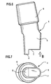
- eine Ansicht ähnlich Figur 2 eines Verbindungsteils mit einer stufenförmigen Endfläche des Einsteckendes und
- Figur 7:
- eine Ansicht des Verbindungsteils der Figur 6 in Richtung des Pfeiles B.
Die in den Figuren 1 bis 3 dargestellte Endoprothese umfaßt einen als
Verankerungsteil wirkenden Schaft 1, der in der Zeichnung nur im
oberen Teil dargestellt ist und der in an sich bekannter Weise in den
Markraum eines Femurs einführbar ist. Der Schaft 1 verbreitert sich in
seinem oberen Teil und weist dort eine sich zur Oberseite hin konisch
öffnende Aufnahmeöffnung 2 auf, deren Längsachse gegenüber der
Längsachse des Schaftes 1 geneigt ist. Die Aufnahmeöffnung 2 wird
von einem ebenen Boden 3 begrenzt, im Querschnitt ist diese Aufnahmeöffnung
2 länglich-oval ausgebildet, so daß die Seitenwand zwei
parallele, ebene Bereiche aufweist, die durch kreisbogenförmige Abschnitte
miteinander verbunden sind.
Die Endoprothese umfaßt weiterhin ein Verbindungsteil 4, das an
einem Ende als Einsteckende 5 ausgebildet ist. Dieses Einsteckende 5
ist komplementär zur Aufnahmeöffnung 2 ausgebildet und paßt somit
exakt in die Aufnahmeöffnung 2 hinein, beim vollständigen Einschieben
des Einsteckendes 5 in die Aufnahmeöffnung 2 liegen die Seitenflächen
des Einsteckendes 5 flächig an den Seitenflächen der Aufnahmeöffnung
2 an, durch die relativ geringe Konizität von Aufnahmeöffnung 2 und
Einsteckende 5 ergibt sich dabei eine selbsthemmende Klemmverbindung.
An seiner dem Einsteckende 5 gegenüberliegenden Seite trägt das
Verbindungsteil 4 einen im Querschnitt kreisförmigen Aufsteckkonus 6,
auf den eine in der Zeichnung nicht dargestellte Gelenkkugel in an sich
bekannter Weise aufgesteckt werden kann.
Das Einsteckende 5 endet in einer dem Boden 3 gegenüberliegenden
Endfläche 7, und von dieser Endfläche 7 steht in einer von der Mittelachse
des Einsteckendes 5 beabstandeten Position, also exzentrisch,
ein stiftförmiger Vorsprung 8 ab, der in einen ihm direkt gegenüberliegenden,
sacklochförmigen Rücksprung 9 im Boden 3 der Aufnahmeöffnung
2 eintaucht.
Durch die exzentrische Anordnung von Vorsprung 8 und Rücksprung 9
ist sichergestellt, daß das Einsteckende 5 nur in einer einzigen Position
in die Aufnahmeöffnung 2 eingesetzt werden kann, wenn das Einsteckende
5 um 180° verdreht in die Aufnahmeöffnung 2 eingesetzt wird,
stößt der Vorsprung 8 in einem Bereich auf den Boden 3 der Aufnahmeöffnung
2 auf, der keinen Rücksprung aufweist, und damit ist das
vollständige Einschieben des Einsteckendes 5 in die Aufnahmeöffnung
2 verhindert.
Der exzentrisch angeordnete Vorsprung 8 und der ihm direkt gegenüberliegende
Rücksprung 9 sichern also das orientierungsrichtige Einsetzen
des Einsteckendes 5 in die Aufnahmeöffnung 2.
Bei dem Ausführungsbeispiel der Figuren 6 und 7 ist eine ähnliche Ausgestaltung
des Verbindungsteils 4 gewählt, jedoch ist der Vorsprung 8
nicht in Form eines Stiftes ausgebildet, sondern ergibt sich durch eine
stufenförmige Ausgestaltung der Endfläche 7. In entsprechender Weise
ist der Boden 3 der Aufnahmeöffnung 2 stufig ausgebildet, so daß der
stufige Vorsprung 8 in einen stufigen Rücksprung 9 eintauchen kann,
wenn das Einsteckende 5 orientierungsrichtig in die Aufnahmeöffnung
2 eingeschoben wird, bei falscher Orientierung stößt dagegen der stufenförmige
Vorsprung 8 auf den Boden 3 auf und verhindert ein vollständiges
Einschieben.
In den Figuren 4a bis 4d ist dargestellt, daß der Rücksprung 9 in Form
einer Bohrung im Boden 3 der Aufnahmeöffnung 2 in unterschiedlicher
exzentrischer Position angeordnet werden kann, in den Figuren 4a bis
4d sind dabei Anordnungen in jeweils einem der vier Quadranten eines
gedachten Achsenkreuzes 10 dargestellt.
In entsprechender Anordnung können stiftförmige Vorsprünge 8 an
unterschiedlichen Verbindungsteilen 4 angeordnet sein, beispielsweise
Verbindungsteilen 4, bei denen der Winkel zwischen der Achse des
Aufsteckkonus 6 und der Achse des Einsteckendes 5 unterschiedlich ist
oder bei denen der Abstand von Aufsteckkonus 6 und Einsteckende 5
unterschiedlich ist. Nur solche Teile können vollständig zusammengesteckt
werden, bei denen Vorsprung 8 und Rücksprung 9 unmittelbar
einander gegenüberliegen, bei allen anderen Kombinationen wird das
vollständige Einschieben durch das Aufsitzen des Vorsprunges 8 auf
dem Boden 3 verhindert. Damit ist eine Zuordnung sichergestellt, die
gewährleistet, daß ein bestimmter Schaft mit einer bestimmten Anordnung
eines Rücksprunges 9 im Boden 3 immer nur mit solchen Verbindungsteilen
4 kombiniert werden kann, bei denen der stiftförmige Vorsprung
8 dem Rücksprung 9 unmittelbar gegenüberliegt, alle anderen
Einsteckenden 5 werden "zurückgewiesen", da sie sich nicht vollständig
einschieben lassen.
Während bei dem Ausführungsbeispiel der Figuren 4a bis 4d jeweils
nur ein einziger Rücksprung 9 in unterschiedlichen Positionen vorgesehen
ist, ist es auch möglich, im Boden 3 mehr als nur einen Rücksprung
9 vorzusehen, und diese Rücksprünge 9 dann den Vorsprüngen
8 in unterschiedlichen Verbindungsteilen 4 gegenüberliegend anzuordnen.
Beim Beispiel der Figur 5a sind zwei derartige Rücksprünge vorgesehen,
beim Beispiel der Figur 5b drei und beim Beispiel der Figur 5c
vier, die Rücksprünge 9 liegen dabei nebeneinander in unterschiedlichen
Positionen. Kombiniert man diese Schäfte mit Verbindungsteilen
4, die an unterschiedlichen Stellen einen oder aber auch mehrere Vorsprünge
8 tragen, dann läßt sich eine sehr selektive Zuordnung erreichen.
In einen Schaft gemäß Figur 5a lassen sich beispielsweise nur
Einsteckenden 5 einschieben, die jeweils nur einen Vorsprung 8 einem
der beiden Rücksprünge 9 gegenüberliegend aurweisen oder die zwei
Vorsprünge 8 aufweisen, die beide jeweils einem Rücksprung 9 gegenüberliegen.
Diese Verbindungsteile 4 würden auch in Schäfte einsetzbar sein, die
gemäß Figur 5b oder 5c ausgebildet sind, diese Schäfte können aber
zusätzlich noch Einsteckenden 5 aufnehmen, die jeweils einen oder
zwei Vorsprünge gegenüberliegend den jeweiligen Rücksprüngen im
Boden aufweisen oder sogar drei derartige Vorsprünge (im Beispiel der
Figur 5b) oder vier derartige Vorsprünge (im Beispiel der Figur 5c).
Man erhält dadurch eine vielfältige Codierungsmöglichkeit für mögliche
Kombinationen einerseits und für ausgeschlossene Kombinationen andererseits.
Diese verschiedenen Codierungsmöglichkeiten sind am Beispiel der
Figuren 4a bis 4d und 5a bis 5c für stiftförmige Vorsprünge und bohrungsförmige
Rücksprünge erläutert worden, es versteht sich, daß dies
auch für stufenförmige Ausgestaltungen der Vorsprünge und Rücksprünge
gilt, in diesem Falle ist die Überdeckung der Vorsprünge 8
bzw. der Rücksprünge 9 unterschiedlich, es werden also die Einzelvorsprünge
und Einzelrücksprünge der Ausführungsbeispiele der Figuren
4a bis 5c ersetzt durch Vorsprünge mit unterschiedlicher Flächenausdehnung,
die Vorsprünge 8 und Rücksprünge 9 der Ausführungsbeispiele
der Figuren 4a bis 5c verschmelzen also sozusagen zu unterschiedlich
großen Vorsprüngen bzw. Rücksprüngen.
Claims (17)
- Endoprothese mit einem Verankerungsteil und einem Verbindungsteil (4), bei der das Verbindungsteil (4) mit einem zapfenförmigen Einsteckende (5) in eine sacklochförmige Aufnahmeöffnung (2) am Verankerungsteil einsteckbar ist, dadurch gekennzeichnet, daß der Boden (3) der Aufnahmeöffnung (2) und die diesem gegenüberliegende Endfläche (7) des Einsteckendes (5) mindestens je einen exzentrisch angeordneten Vor- bzw. Rücksprung (8; 9) aufweisen, die bei in die Aufnahmeöffnung (2) eingesetztem Einsteckende (5) ineinandergreifen.
- Endoprothese nach Anspruch 1, dadurch gekennzeichnet, daß der Vorsprung (8) an der Endfläche (7) des Einsteckendes (5) und der Rücksprung (9) im Boden (3) der Aufnahmeöffnung (2) angeordnet sind.
- Endoprothese nach Anspruch 1 oder 2, dadurch gekennzeichnet, daß Vor- und Rücksprung (8; 9) durch eine stufenförmige Ausbildung der Endfläche (7) des Einsteckendes (5) und des Bodens (3) der Aufnahmeöffnung (2 ) gebildet sind.
- Endoprothese nach einem der Ansprüche 1 oder 2, dadurch gekennzeichnet, daß der Vorsprung (8) die Form eines Stiftes oder Zapfens aufweist.
- Endoprothese nach einem der Ansprüche 1 und 2 oder 4, dadurch gekennzeichnet, daß der Rücksprung (9) die Form einer Bohrung aufweist.
- Endoprothese nach Anspruch 5, dadurch gekennzeichnet, daß die Bohrung als Innengewindebohrung ausgebildet ist.
- Endoprothese nach einem der voranstehenden Ansprüche, dadurch gekennzeichnet, daß das Verankerungsteil der Schaft (1) einer Femurprothese ist.
- Endoprothese nach einem der voranstehenden Ansprüche, dadurch gekennzeichnet, daß das Einsteckende (5) und die Aufnahmeöffnung (2) konisch ineinanderpassend ausgebildet sind.
- Endoprothese nach einem der voranstehenden Ansprüche, dadurch gekennzeichnet, daß das Einsteckende (5) und die Aufnahmeöffnung (2) im Querschnitt länglich-oval ausgebildet sind.
- Endoprothese nach einem der voranstehenden Ansprüche, dadurch gekennzeichnet, daß das Verbindungsteil (4) an seinem dem Einsteckende (5) gegenüberliegenden Ende eine Aufnahme (6) für eine Gelenkkugel aufweist.
- Bausatz für eine Endoprothese nach einem der Ansprüche 5 bis 10 mit mehreren Verankerungsteilen und mehreren Verbindungsteilen, dadurch gekennzeichnet, daß Vorsprung und Rücksprung (8; 9) bei verschiedenen Teilen (4; 1) des Bausatzes an verschiedenen Stellen am Boden (3) der Aufnahmeöffnung (2) und an der Endfläche (7) des Einsteckendes (5) angeordnet sind, so daß nur bei bestimmten Kombinationen eines Verankerungsteils (1) und eines Verbindungsteils (4) beim Zusammenstecken ein Eingriff eines Vorsprunges (8) und eines Rücksprunges (9) auftritt.
- Bausatz nach Anspruch 11, dadurch gekennzeichnet, daß an einem Teil (1) des Bausatzes in mehreren Positionen ein Rücksprung (9) angeordnet ist, so daß dieses mit Teilen (4) kombinierbar ist, bei denen der Vorsprung (8) unterschiedlich angeordnet ist.
- Bausatz nach Anspruch 12, dadurch gekennzeichnet, daß an einem Teil (4) des Bausatzes in mehreren Positionen ein Vorsprung (8) angeordnet ist, so daß dieses Teil (4) nur mit Teilen (1) kombinierbar ist, bei denen ein Rücksprung (9) an mehreren, mit den Positionen der Vorsprünge (8) übereinstimmenden Positionen angeordnet ist.
- Bausatz nach einem der Ansprüche 12 oder 13, dadurch gekennzeichnet, daß ein gemeinsamer Rücksprung (9) vorgesehen ist, der sich über mehrere mögliche Positionen eines Vorsprunges (8) am anderen Teil (4) erstreckt.
- Bausatz nach einem der Ansprüche 12 oder 13, dadurch gekennzeichnet, daß in mehreren Positionen angeordnete, voneinander getrennte Rücksprünge (9) vorgesehen sind.
- Bausatz nach einem der Ansprüche 13 bis 15, dadurch gekennzeichnet, daß in mehreren Positionen angeordnete, voneinander getrennte Vorsprünge (8) vorgesehen sind.
- Bausatz nach einem der Ansprüche 13 oder 14, dadurch gekennzeichnet, daß ein gemeinsamer Vorsprung (8) vorgesehen ist, der sich über mehrere mögliche Positionen eines Rücksprunges (9) am anderen Teil (1) erstreckt.
Applications Claiming Priority (3)
| Application Number | Priority Date | Filing Date | Title |
|---|---|---|---|
| DE10214808A DE10214808A1 (de) | 2002-04-04 | 2002-04-04 | Endoprothese |
| DE10214808 | 2002-04-04 | ||
| DE20205205U DE20205205U1 (de) | 2002-04-04 | 2002-04-04 | Endoprothese |
Publications (1)
| Publication Number | Publication Date |
|---|---|
| EP1350486A1 true EP1350486A1 (de) | 2003-10-08 |
Family
ID=30001456
Family Applications (1)
| Application Number | Title | Priority Date | Filing Date |
|---|---|---|---|
| EP03006677A Withdrawn EP1350486A1 (de) | 2002-04-04 | 2003-03-26 | Endoprothese |
Country Status (2)
| Country | Link |
|---|---|
| EP (1) | EP1350486A1 (de) |
| DE (2) | DE20205205U1 (de) |
Cited By (4)
| Publication number | Priority date | Publication date | Assignee | Title |
|---|---|---|---|---|
| FR2865927A1 (fr) * | 2004-02-10 | 2005-08-12 | Biomet Merck France | Prothese de hanche a col modulaire |
| US7179298B2 (en) * | 2005-05-27 | 2007-02-20 | Greenlee Wilfred E | Hip prosthesis and the use thereof |
| WO2008003597A1 (de) * | 2006-07-03 | 2008-01-10 | Aesculap Ag & Co. Kg | Implantat |
| US7914584B2 (en) | 2004-10-21 | 2011-03-29 | Biomet Manufacturing Corp. | Prosthesis system with trunnion and removably coupled head |
Families Citing this family (1)
| Publication number | Priority date | Publication date | Assignee | Title |
|---|---|---|---|---|
| DE20205205U1 (de) * | 2002-04-04 | 2002-06-06 | Aesculap AG & Co. KG, 78532 Tuttlingen | Endoprothese |
Citations (17)
| Publication number | Priority date | Publication date | Assignee | Title |
|---|---|---|---|---|
| FR2349319A2 (fr) * | 1976-04-26 | 1977-11-25 | Rambert Andre | Prothese de la hanche |
| FR2574283A1 (fr) * | 1984-12-07 | 1986-06-13 | Tornier Sa | Prothese du col du femur a boule excentree |
| EP0201407A1 (de) * | 1985-04-24 | 1986-11-12 | Patrick Montagne | Bausatz zum Aufbauen einer femoralen Prothese |
| EP0290735A1 (de) * | 1987-05-15 | 1988-11-17 | GebràDer Sulzer Aktiengesellschaft | Bausatz zum intraoperativen Aufbau einer Femurkopfprothese |
| EP0310566A2 (de) * | 1987-08-03 | 1989-04-05 | G. CREMASCOLI S.p.A. | Anpassbare Hüftprothese |
| FR2626168A1 (fr) * | 1988-01-21 | 1989-07-28 | Cremascoli Spa | Prothese de hanche modulaire |
| EP0339530A2 (de) * | 1988-04-26 | 1989-11-02 | S + G Implants Gmbh | Endoprothese für ein Gelenk |
| US4963155A (en) * | 1989-08-30 | 1990-10-16 | Zimmer, Inc. | Attachment mechanism for modular surgical products |
| US4963161A (en) | 1989-07-10 | 1990-10-16 | At&T Bell Laboratories | Non-aqueous alkali battery having an improved cathode |
| FR2647669A1 (fr) * | 1989-05-30 | 1990-12-07 | Vialla Jean Marie | Prothese de hanche anatomique |
| EP0457222A1 (de) * | 1990-05-18 | 1991-11-21 | Intraplant AG | Femurprothese |
| FR2693367A1 (fr) * | 1992-07-09 | 1994-01-14 | Lepine Groupe | Tige fémorale pour prothèse de hanche. |
| FR2721200A1 (fr) * | 1994-06-17 | 1995-12-22 | Cremascoli France | Prothèse de hanche du type comportant une tige avec logement pour col amovible. |
| US5653764A (en) * | 1994-02-17 | 1997-08-05 | Murphy; Stephen B. | Modular hip prosthesis with discrete selectable angular orientation |
| EP0797964A1 (de) | 1996-03-26 | 1997-10-01 | Groupe Lepine | Satz von Elementen zum Erzeugen einer Totalhüftprothese |
| US6048365A (en) * | 1998-04-01 | 2000-04-11 | Sulzer Orthopedics Inc. | Implantable orthopedic prosthesis having keyed taper connector |
| DE20205205U1 (de) * | 2002-04-04 | 2002-06-06 | Aesculap AG & Co. KG, 78532 Tuttlingen | Endoprothese |
Family Cites Families (2)
| Publication number | Priority date | Publication date | Assignee | Title |
|---|---|---|---|---|
| DE3731421C2 (de) * | 1987-09-18 | 1997-04-17 | Eska Implants Gmbh & Co | Femur-Hüftgelenk-Endoprothese |
| DE19940348C5 (de) * | 1999-04-27 | 2006-07-13 | Steinicke Maschinen- Und Werkzeugbau Ag | Zweiteilige Endoprothese, insbesondere für ein künstliches Hüftgelenk |
-
2002
- 2002-04-04 DE DE20205205U patent/DE20205205U1/de not_active Expired - Lifetime
- 2002-04-04 DE DE10214808A patent/DE10214808A1/de not_active Withdrawn
-
2003
- 2003-03-26 EP EP03006677A patent/EP1350486A1/de not_active Withdrawn
Patent Citations (19)
| Publication number | Priority date | Publication date | Assignee | Title |
|---|---|---|---|---|
| FR2349319A2 (fr) * | 1976-04-26 | 1977-11-25 | Rambert Andre | Prothese de la hanche |
| FR2574283A1 (fr) * | 1984-12-07 | 1986-06-13 | Tornier Sa | Prothese du col du femur a boule excentree |
| EP0201407B1 (de) | 1985-04-24 | 1990-07-18 | Patrick Montagne | Bausatz zum Aufbauen einer femoralen Prothese |
| EP0201407A1 (de) * | 1985-04-24 | 1986-11-12 | Patrick Montagne | Bausatz zum Aufbauen einer femoralen Prothese |
| EP0290735A1 (de) * | 1987-05-15 | 1988-11-17 | GebràDer Sulzer Aktiengesellschaft | Bausatz zum intraoperativen Aufbau einer Femurkopfprothese |
| EP0310566B1 (de) | 1987-08-03 | 1993-12-01 | G. CREMASCOLI S.p.A. | Anpassbare Hüftprothese |
| EP0310566A2 (de) * | 1987-08-03 | 1989-04-05 | G. CREMASCOLI S.p.A. | Anpassbare Hüftprothese |
| FR2626168A1 (fr) * | 1988-01-21 | 1989-07-28 | Cremascoli Spa | Prothese de hanche modulaire |
| EP0339530A2 (de) * | 1988-04-26 | 1989-11-02 | S + G Implants Gmbh | Endoprothese für ein Gelenk |
| FR2647669A1 (fr) * | 1989-05-30 | 1990-12-07 | Vialla Jean Marie | Prothese de hanche anatomique |
| US4963161A (en) | 1989-07-10 | 1990-10-16 | At&T Bell Laboratories | Non-aqueous alkali battery having an improved cathode |
| US4963155A (en) * | 1989-08-30 | 1990-10-16 | Zimmer, Inc. | Attachment mechanism for modular surgical products |
| EP0457222A1 (de) * | 1990-05-18 | 1991-11-21 | Intraplant AG | Femurprothese |
| FR2693367A1 (fr) * | 1992-07-09 | 1994-01-14 | Lepine Groupe | Tige fémorale pour prothèse de hanche. |
| US5653764A (en) * | 1994-02-17 | 1997-08-05 | Murphy; Stephen B. | Modular hip prosthesis with discrete selectable angular orientation |
| FR2721200A1 (fr) * | 1994-06-17 | 1995-12-22 | Cremascoli France | Prothèse de hanche du type comportant une tige avec logement pour col amovible. |
| EP0797964A1 (de) | 1996-03-26 | 1997-10-01 | Groupe Lepine | Satz von Elementen zum Erzeugen einer Totalhüftprothese |
| US6048365A (en) * | 1998-04-01 | 2000-04-11 | Sulzer Orthopedics Inc. | Implantable orthopedic prosthesis having keyed taper connector |
| DE20205205U1 (de) * | 2002-04-04 | 2002-06-06 | Aesculap AG & Co. KG, 78532 Tuttlingen | Endoprothese |
Cited By (5)
| Publication number | Priority date | Publication date | Assignee | Title |
|---|---|---|---|---|
| FR2865927A1 (fr) * | 2004-02-10 | 2005-08-12 | Biomet Merck France | Prothese de hanche a col modulaire |
| EP1566155A1 (de) * | 2004-02-10 | 2005-08-24 | Biomet France | Hüftprothese mit modularem Hals |
| US7914584B2 (en) | 2004-10-21 | 2011-03-29 | Biomet Manufacturing Corp. | Prosthesis system with trunnion and removably coupled head |
| US7179298B2 (en) * | 2005-05-27 | 2007-02-20 | Greenlee Wilfred E | Hip prosthesis and the use thereof |
| WO2008003597A1 (de) * | 2006-07-03 | 2008-01-10 | Aesculap Ag & Co. Kg | Implantat |
Also Published As
| Publication number | Publication date |
|---|---|
| DE20205205U1 (de) | 2002-06-06 |
| DE10214808A1 (de) | 2003-10-23 |
Similar Documents
| Publication | Publication Date | Title |
|---|---|---|
| EP0977529B1 (de) | Zwischenwirbelimplantat | |
| EP0145641B1 (de) | Bausatz für eine Resektionsprothese | |
| EP1200222B1 (de) | Bohrer mit auswechselbarem schneidkopf | |
| DE10055888C1 (de) | Knochenschraube | |
| DE602004001398T2 (de) | Knochenverbindungsvorrichtung | |
| DE69512497T2 (de) | Sphärische Oberarmprothese | |
| DE4028510C2 (de) | Endoprothese | |
| DE60107882T2 (de) | Schulterendoprothese für Brüche des oberen Endes des Oberarmknochens | |
| DE69610185T2 (de) | Vorrichtung zur Prothesenfixierung, insbesondere einer Schulterblattgelenkpfannenprothese | |
| DE69626006T2 (de) | Tibiale prothese | |
| DE69813807T2 (de) | Implantat als platzhalter zwischen wirbelkörpern | |
| EP1639968A1 (de) | Implantat mit einem in eine Knochenhöhlung einzusetzenden und darin zu verankernden Teil | |
| EP1476098A1 (de) | Zwischenwirbelimplantat | |
| EP1459710A2 (de) | Implantat zum Einsetzen zwischen Wirbelkörper der Wirbelsäule | |
| DE3538654A1 (de) | Bohrsystem, enthaltend eine bohrlehre zum einsetzen einer endoprothese sowie zugehoerige prothese | |
| EP1418852A1 (de) | Interspinale prothese | |
| DE102006041551A1 (de) | Schulterprothese | |
| DE19816832C1 (de) | Wirbelkörperfusionsimplantat | |
| DE3414514A1 (de) | Einschraubpfanne fuer ein kuenstliches hueftgelenk | |
| EP1088531B1 (de) | Gelenkendoprothese | |
| EP1833393A1 (de) | Osteosyntheseplatte, beispielsweise radius- oder humeruskopfplatte, mit einer vielzahl von bohrungen zur aufnahme von knochenschrauben | |
| EP0462357A2 (de) | Oberschenkelteil einer Hüftgelenkendoprothese | |
| DE10214808A1 (de) | Endoprothese | |
| CH677072A5 (en) | Spherical joint for hip joint prosthesis - includes cup shaped half with tapered metal shell carrying cutting thread formed by saw teeth | |
| EP1675517B1 (de) | Vorrichtung zur knochenfixation |
Legal Events
| Date | Code | Title | Description |
|---|---|---|---|
| PUAI | Public reference made under article 153(3) epc to a published international application that has entered the european phase |
Free format text: ORIGINAL CODE: 0009012 |
|
| AK | Designated contracting states |
Kind code of ref document: A1 Designated state(s): AT BE BG CH CY CZ DE DK EE ES FI FR GB GR HU IE IT LI LU MC NL PT RO SE SI SK TR |
|
| AX | Request for extension of the european patent |
Extension state: AL LT LV MK |
|
| AKX | Designation fees paid | ||
| REG | Reference to a national code |
Ref country code: DE Ref legal event code: 8566 |
|
| STAA | Information on the status of an ep patent application or granted ep patent |
Free format text: STATUS: THE APPLICATION IS DEEMED TO BE WITHDRAWN |
|
| 18D | Application deemed to be withdrawn |
Effective date: 20040409 |