EP1350296B1 - Bobines d'extremite refroidies par gaz pour rotor de moteur electrodynamique et procede de refroidissement de bobines d'extremite - Google Patents
Bobines d'extremite refroidies par gaz pour rotor de moteur electrodynamique et procede de refroidissement de bobines d'extremite Download PDFInfo
- Publication number
- EP1350296B1 EP1350296B1 EP01271684A EP01271684A EP1350296B1 EP 1350296 B1 EP1350296 B1 EP 1350296B1 EP 01271684 A EP01271684 A EP 01271684A EP 01271684 A EP01271684 A EP 01271684A EP 1350296 B1 EP1350296 B1 EP 1350296B1
- Authority
- EP
- European Patent Office
- Prior art keywords
- rotor
- spaceblock
- endwindings
- cavity
- outlet opening
- Prior art date
- Legal status (The legal status is an assumption and is not a legal conclusion. Google has not performed a legal analysis and makes no representation as to the accuracy of the status listed.)
- Expired - Lifetime
Links
Images


Classifications
-
- H—ELECTRICITY
- H02—GENERATION; CONVERSION OR DISTRIBUTION OF ELECTRIC POWER
- H02K—DYNAMO-ELECTRIC MACHINES
- H02K1/00—Details of the magnetic circuit
- H02K1/06—Details of the magnetic circuit characterised by the shape, form or construction
- H02K1/22—Rotating parts of the magnetic circuit
- H02K1/32—Rotating parts of the magnetic circuit with channels or ducts for flow of cooling medium
-
- H—ELECTRICITY
- H02—GENERATION; CONVERSION OR DISTRIBUTION OF ELECTRIC POWER
- H02K—DYNAMO-ELECTRIC MACHINES
- H02K3/00—Details of windings
- H02K3/04—Windings characterised by the conductor shape, form or construction, e.g. with bar conductors
- H02K3/24—Windings characterised by the conductor shape, form or construction, e.g. with bar conductors with channels or ducts for cooling medium between the conductors
-
- H—ELECTRICITY
- H02—GENERATION; CONVERSION OR DISTRIBUTION OF ELECTRIC POWER
- H02K—DYNAMO-ELECTRIC MACHINES
- H02K3/00—Details of windings
- H02K3/46—Fastening of windings on the stator or rotor structure
- H02K3/50—Fastening of winding heads, equalising connectors, or connections thereto
- H02K3/51—Fastening of winding heads, equalising connectors, or connections thereto applicable to rotors only
-
- H—ELECTRICITY
- H02—GENERATION; CONVERSION OR DISTRIBUTION OF ELECTRIC POWER
- H02K—DYNAMO-ELECTRIC MACHINES
- H02K9/00—Arrangements for cooling or ventilating
- H02K9/08—Arrangements for cooling or ventilating by gaseous cooling medium circulating wholly within the machine casing
Definitions
- the present invention relates to a structure and method for enhanced cooling of generator rotors by directing multiple streams of cooling gas into cavity spaces between rotor end coils for creating multiple interacting circulation cells and directed flow jets.
- the power output rating of dynamoelectric machines is often limited by the ability to provide additional current through the rotor field winding because of temperature limitations imposed on the electrical conductor insulation. Therefore, effective cooling of the rotor winding contributes directly to the output capability of the machine. This is especially true of the rotor end region, where direct, forced cooling is difficult and expensive due to the typical construction of these machines. As prevailing market trends require higher efficiency and higher reliability in lower cost, higher-power density generators, cooling the rotor end region becomes a limiting factor.
- Turbo-generator rotors typically consist of concentric rectangular coils mounted in slots in a rotor.
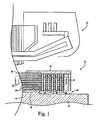
- the end portions of the coils (commonly referred to as endwindings), which are beyond the support of the main rotor body, are typically supported against rotational forces by a retaining ring (see FIGURE 1 ).
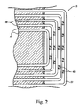
- Support blocks are placed intermittently between the concentric coil endwindings to maintain relative position and to add mechanical stability for axial loads, such as thermal loads (see FIGURE 2 ).
- the copper coils are constrained radially by the retaining ring on their outer radius, which counteracts centrifugal forces. The presence of the spaceblocks and retaining ring results in a number of coolant regions exposed to the copper coils.
- the primary coolant path is axial, between the spindle and the bottom of the endwindings. Also, discrete cavities are formed between coils by the bounding surfaces of the coils, blocks and the inner surface of the retaining ring structure.
- the endwindings are exposed to coolant that is driven by rotational forces from radially below the endwindings into these cavities (see FIGURE 3 ).
- This heat transfer tends to be low. This is because according to computed flow pathlines in a single rotating end winding cavity from a computational fluid dynamic analysis, the coolant flow enters the cavity, traverses through a primary circulation and exits the cavity. Typically, the circulation results in low heat transfer coefficients especially near the center of the cavity. Thus, while this is a means for heat removal in the endwindings, it is relatively inefficient.
- Some systems penetrate the highly stressed rotor retaining ring with radial holes to allow cooling gas to be pumped directly alongside the rotor endwindings and discharged into the air gap, although such systems can have only limited usefulness due to the high mechanical stress and fatigue life considerations relating to the retaining ring.
- Passive cooling provides the advantage of minimum complexity and cost, although heat removal capability is diminished when compared with the active systems of direct and forced cooling. Any cooling gas entering the cavities between concentric rotor windings must exit through the same opening since these cavities are otherwise enclosed - the four "side walls" of a typical cavity are formed by the concentric conductors and the insulating blocks that separate them, with the "bottom” (radially outward) wall formed by the retaining ring that supports the endwindings against rotation. Cooling gas enters from the annular space between the conductors and the rotor spindle. Heat removal is thus limited by the low circulation velocity of the gas in the cavity and the limited amount of the gas that can enter and leave these spaces.
- the cooling gas in the end region has not yet been fully accelerated to rotor speed, that is, the cooling gas is rotating at part rotor speed.
- the heat transfer coefficient is typically highest near the spaceblock that is downstream relative to the flow direction - where the fluid enters with high momentum and where the fluid coolant is coldest.
- the heat transfer coefficient is also typically high around the cavity periphery. The center of the cavity receives the least cooling.
- DE 100 27 377 describes an electric machine, such as a turbine generator, that has an insulating coil supporting element between end sections that defines a volume open to a rotor coil surface and connected to the coil's inner peripheral opening.
- the invention described herein overcomes the difficulties inherent in a single large circulation cell for increasing heat transfer. Rather than injecting cooling flow in the direction of the single circulation cell to augment it, as described in USP 5,644,179 , the invention describes an endwinding assemby and a method for creating multiple circulation cells that penetrate the center region of the cavity, thereby significantly increasing the heat transfer in a region that would otherwise be devoid of cooling flow. The same benefit extends to the corner regions of the cavity as well.
- the endwinding assembly and method of the invention substantially increase the heat transfer performance in all regions of the rotor endwinding cavity by creating multiple circulating cells and cooling jets.
- the overall cooling effectiveness is significantly increased, thereby increasing the power rating of the machine.
- the system is low cost, easily installed and robust, thereby providing a practical solution to a complex problem, contributing to the marketability of the power generator.
- the invention is embodied in a gas cooled dynamoelectric machine, as defined in appended claim 1.
- the invention is further embodied in a method of cooling a dynamoelectric machine as defined in appended claim 6.
- FIGURES 1 and 2 show a rotor 10 for a gas-cooled dynamoelectric machine, which also includes a stator 12 surrounding the rotor.
- the rotor includes a generally cylindrical body portion 14 centrally disposed on a rotor spindle 16 and having axially opposing end faces, of which a portion 18 of one end face is shown in FIGURE 1 .
- the body portion is provided with a plurality of circumferentially-spaced, axially extending slots 20 for receiving concentrically arranged coils 22, which make up the rotor winding. For clarity, only five rotor coils are shown, although several more are commonly used in practice.
- a number of conductor bars 24 constituting a portion of the rotor winding are stacked in each one of the slots. Adjacent conductor bars are separated by layers of electrical insulation 22.
- the stacked conductor bars are typically maintained in the slots by wedges 26 ( FIGURE 1 ) and are made of a conductive material such as copper.
- the conductor bars 24 are interconnected at each opposing end of the body portion by end turns 27, which extend axially beyond the end faces to form stacked endwindings 28. The end turns are also separated by layers of electrical insulation.
- a retaining ring 30 is disposed around the end turns at each end of the body portion to hold the endwindings in place against centrifugal forces.
- the retaining ring is fixed at one end to the body portion and extends out over the rotor spindle 16.
- a centering ring 32 is attached to the distal end of the retaining ring 30. It should be noted that the retaining ring 30 and the center ring 32 can be mounted in other ways, as is known in the art.
- the inner diameter of the centering ring 32 is radially spaced from the rotor spindle 16 so as to form a gas inlet passage 34 and the endwindings 28 are spaced from the spindle 16 so as to define an annular region 36.
- a number of axial cooling channels 38 formed along slots 20 are provided in fluid communication with the gas inlet passage 34 via the annular region 36 to deliver cooling gas to the coils 22.
- the endwindings 28 at each end of the rotor 10 are circumferentially and axially separated by a number of spacers or spaceblocks 40.
- the spaceblocks are elongated blocks of an insulating material located in the spaces between adjacent endwindings 28 and extend beyond the full radial depth of the endwindings into the annular gap 36. Accordingly, the spaces between the concentric stacks of the end turns (hereinafter endwindings) are divided into cavities. These cavities are bounded on the top by the retaining ring 30 and on four sides by adjacent endwindings 28 and adjacent spaceblocks 40.
- each of these cavities is in fluid communication with the gas inlet passage 34 via the annular region 36.
- a portion of the cooling gas entering the annular region 36 between the endwinding 28 and the rotor spindle 16 through the gas inlet passage 34 thus enters the cavities 42, circulates therein, and then returns to the annular region 36 between the endwinding and the rotor spindle. Air flow is shown by the arrows in FIGURES 1 and 3 .
- FIGURE 3 The inherent pumping action and rotational forces acting in a rotating generator cavity produce a large single flow circulation cell, as schematically shown in FIGURE 3 .
- This flow circulation cell exhibits its highest velocity near the peripheral edges of the cavity, leaving the center region inadequately cooled due to the inherently low velocity in the center region of the cavity.
- large areas of the corner regions are also inadequately cooled because the circular motion of the flow cell does not carry cooling flow into the corners.
- each spaceblock 140 is provided with an internal cooling gas duct 144 that in this embodiment has a discharge port or outlet opening 146 in the block at the center region of the respective cavity 142 so that the coolant flow creates a counter rotating pair of circular cells in the cavity thus providing for increased heat transfer in all regions of the cavity, including both the center and corner regions which have typically been deprived of coolant flow.
- Each cooling duct 144 lies along the length of the spaceblock 140 and is thus oriented radially with respect to the rotor axis.
- the duct extends from a point radially inwardly of or below the endwindings 28 to a point generally centrally of the radial height of the endwinding and thus provides a passage through which cooling gas can flow from the annular region 36 between the endwindings 28 and the rotor spindle 16 into the cavities 142.
- each duct 144 extends from an inlet opening 150 located near the radially inward end of the spaceblock 140 to an outlet opening 146 located about midway along the length of the spaceblock.
- the inlet opening 150 is disposed on a circumferentially-oriented upstream surface of the spaceblock for receiving the cooling flow. As seen in FIGURE 6 , in this exemplary embodiment, the inlet opening is located on the portion of the spaceblock that extends below the endwinding so as to be fluid communication with the annular region 36 between the endwinding 28 and the rotor spindle 16.
- the outlet opening 146 is also disposed on a circumferentially oriented surface of the spaceblock and is fluid communication with one of the cavities 142 bounded by the spaceblock.
- the coolant flow is driven radially through the block by impact pressure, resulting from the relative velocity of the gas entering the rotor end region, and the centrifugal pumping of the rotor.
- the coolant flow is directed through discharge port(s) 150 in the spaceblock(s) into the center region of the adjacent cavity(s).
- This directed jet of coolant creates a counter-rotating pair of circulating cells in the cavity.
- This pair of cells then drives additional circulation cells, providing increased heat transfer in all regions of the cavity, including the center region and the cavity corners that would otherwise be deprived of coolant flow.
- the main coolant jet adds to the heat transfer performance and exits from the rotating cavity as shown.
- cooling gas In operation, rotor rotation will cause cooling gas to be drawn through the gas inlet passage 34 ( FIGURE 1 ) into the annular region 36 between the endwinding and the rotor spindle ( FIGURE 6 ).
- the cooling gas is driven through inlet openings 150 into duct 144.
- the cooling gas in duct 144 is expelled into the corresponding cavity from the respective outlet opening 146.
- the outlet opening is located at about a radial mid-point of the cavity so that the coolant flow is directed from the duct 144 in the block into the center region of the cavity 142.
- the generation of multiple circulating cells facilitates heat removal from all parts of the cavity including the central region and corner regions that the prior art single circulating cell tended to bypass.
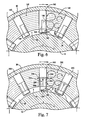
- FIGURE 7 shows another embodiment of the invention where the support blocks discharge cooling jets to enter each cavity from opposite directions, thereby strengthening the counter-rotating cells and providing even more through flow. More specifically, FIGURE 7 shows a partial section of the rotor endwinding showing cavities 242 with the direction of rotation indicated by arrow X.
- each spaceblock 240 is provided with an internal cooling gas duct 244 for creating multiple circulating cells inside the cavity to increase heat removal.
- each cooling gas duct 244 is oriented radially with respect to the rotor and extends from a point radially inwardly of or below the endwinding 28 to a point near the central region of the spaceblock.
- each duct 244 extends from an inlet opening 250 located near the radially inward end of the spaceblock to first and second outlet openings 246, 248 located near the central region of the spaceblock 240 and the respective cavity.
- the inlet opening is disposed on a circumferentially-oriented surface of the spaceblock for receiving coolant flow as indicated by arrow A.
- the inlet opening 250 is located on the portion of the spaceblock that extends below the endwinding 28 so as to be fluid communication with the annular region 36 between the endwinding 28 and the rotor spindle 16.
- first and second outlet openings 246,248 are provided, one disposed on each circumferentially oriented surface of the spaceblock 240 so as to be in fluid communication with respective cavities 242 that are bounded by the spaceblock.
- a partition 252 is provided in the radial duct 244 to define first and second radial duct passage portions 254,256 that are circumferentially adjacent in the spaceblock. If deemed necessary or desirable, the partition may extend into the circumferential portion of the passage indicated by reference 258 so that coolant flow is suitably deflected in generally equal amounts to the respective passage portions 254,256 for flow out of the respective outlet openings 246,248.
- the coolant flow is directed from the ducted block 240 to the center region of each cavity 242 from both circumferential sides of the cavity. This creates stronger multiple circulation cells, providing enhanced heat transfer in the center of the cavity and all other regions of the cavity.
- the coolant flow enters the ducted block driven by impact pressure and centrifugal pumping.
- FIGURE 8 shows an embodiment of the invention where multiple discharge ports provide coolant flow to all regions of the cavity, again increasing heat transfer by overcoming the inherent heat transfer difficulties resulting from the naturally occurring single large circulation cell in the rotating cavity.
- FIGURE 8 shows a partial section of the rotor endwinding showing circumferentially adjacent cavities 342, with a direction of rotation indicated by arrow X.
- each spaceblock 340 is provided with an internal cooling duct 344 for directing cooling flow to generally all regions of the cavity for enhanced heat transfer.
- each cooling gas duct is oriented radially with respect to the rotor and extends from an inlet opening 350 disposed radially inwardly of or below the endwinding 28.
- the cooling gas duct extends to a point near the retaining ring 30 and a plurality of outlets 360, 362, 364 are defined at spaced locations along the length of the cooling gas duct.
- each duct extends from an inlet opening 350 located near the radially inward end of the spaceblock to a plurality of outlet openings including a first outlet opening 360 disposed approximately one third of the length along the spaceblock 340, a second outlet opening 362 disposed approximately two thirds of the length along the outlet, and a third outlet opening 364 disposed adjacent the retaining ring 30.
- a plurality of exhaust holes may be defined to extend from the cooling duct in each circumferential direction of the spaceblock to direct flow into each of the respective cavities bounded by the spaceblock, to further ensure full distribution of the cooling flow through the cavity.
- the exhaust holes or outlet opening 360, 362, 364 direct the coolant flow generally circumferentially and are thus disposed in a plane disposed at an angle of about 90 degrees with respect to the axis of the rotor.
- the cross-sectional view shown in FIGURE 9 represents an alternate form of the embodiment of FIGURE 8.
- FIGURE 9 shows a variation and improvement on the multiple cooling jets from FIGURE 8 by directing the jets such that they impinge directly on the heated walls of the rotating cavity, thereby increasing heat transfer even more.
- this embodiment generally corresponds to the embodiment of FIGURE 8 except that exhaust passage(s) 462 (only one of which is shown on FIGURE 9 ) for passage 444 in the spaceblock 440 inclined so as to be defined in a plane that is disposed at an angle of ⁇ 90° with respect to the axis of the rotor, to aim the cooling jet to impinge directly on the endwinding 28 thus increasing heat transfer.
- the exhaust passages may direct cooling gas to either of the axially adjacent rotor endwindings, or one or more of the exhaust passages can direct the cooling jet towards one axially adjacent rotor endwinding and one or more others of the exhaust holes can direct their respective cooling jet towards the other of the two rotor endwinding bounding the cavity.
- circumferentially adjacent spaceblocks can direct the cooling jets to respectively alternating rotor endwindings.
- Other permutations and combinations of the cooling jet directed flow could be adopted, as will be evident from a consideration of the foregoing.
- the cavities between endwindings comprise circumferentially oriented or "endstrap" cavities and axial coil side cavities.
- endstrap cavities are shown in FIGURES 6-8
- the present invention is equally applicable to the axial coil side cavities.
- the primary difference between such cavities is that the axial coil side cavities are oriented transverse to the direction of rotation, instead of being oriented along the direction of rotation as the endstrap cavities are.
- This means that the relationship of the axial velocity component and circumferential velocity component to the cavity would be reversed such that the circumferentially velocity component would be perpendicular to the cavity and the axial velocity component would be parallel to the cavities.
- the inlet opening and outlet opening would be oriented 90° relative to each other so that the inlet faces the circumferential direction and the outlet faces axially.
Claims (6)
- Machine dynamoélectrique refroidie par gaz, comprenant :un rotor (10) ayant une partie (14) de corps, ledit rotor ayant des bobines (22) s'étendant axialement et des bobines d'extrémité (28) s'étendant axialement au-delà d'au moins une extrémité (18) de ladite partie (14) de corps ;une pluralité de blocs d'espacement (140, 240) disposée entre lesdites bobines d'extrémité (28) et orientée radialement par rapport à l'axe du rotor ;une pluralité de cavités (142, 242, 342) étant définie entre des bobines d'extrémité (28) mutuellement adjacentes et des blocs d'espacement (140, 240, 340, 440) ;au moins un dit bloc d'espacement ayant un conduit (144, 244, 344, 444) s'étendant radialement défini à l'intérieur de celui-ci, ledit conduit s'étendant entre un orifice d'admission (150, 250, 350) et un orifice de sortie (146, 246, 248, 362, 462) ;dans laquelle ledit orifice de sortie est disposé dans une surface dudit au moins un bloc d'espacement faisant face à une cavité adjacente à celui-ci ; etdans laquelle ledit orifice d'admission (150, 250, 350) est formé sur une surface orientée circonférentiellement dudit au moins un bloc d'espacement (140, 240, 340, 440) ; caractérisée parledit orifice de sortie (146, 246, 248, 362, 462) étant défini radialement dans une section intermédiaire dudit bloc d'espacement (140, 240, 340, 440) de sorte à émettre ledit flux de gaz de refroidissement généralement en direction d'une région centrale de ladite cavité (142, 242, 342) ; etdans laquelle il y a une pluralité d'orifices de sortie, au moins un dit orifice de sortie étant dirigé à un angle de moins de 90 degrés par rapport à un axe dudit rotor de sorte que le gaz de refroidissement heurte une bobine d'extrémité adjacente à celle-ci.
- Machine dynamoélectrique selon la revendication 1, dans laquelle ledit orifice d'admission (150, 250, 350) est situé de manière adjacente à une extrémité radialement vers l'intérieur dudit au moins bloc d'espacement (140, 240, 340, 440).
- Machine dynamoélectrique selon la revendication 1, dans laquelle ledit orifice de sortie (146, 246, 248, 362, 462) est formé sur une surface orientée circonférentiellement dudit au moins un bloc d'espacement (140, 240, 340, 440).
- Machine dynamoélectrique selon la revendication 1, dans laquelle une pluralité desdits blocs d'espacement (140, 240, 340, 440) a un conduit (144, 244, 344, 444) s'étendant radialement formé dans celle-ci.
- Machine dynamoélectrique selon la revendication 1, dans laquelle il y a une pluralité d'orifices de sortie (246, 248, 360, 362, 364, 462), au moins un dit orifice de sortie (246, 248, 362, 462) émettant ledit flux de gaz de refroidissement généralement en direction d'une région centrale de ladite cavité.
- Procédé de refroidissement de bobines d'extrémité dans une machine dynamoélectrique comprenant un rotor (10) ayant une partie (14) de corps, des bobines (22) s'étendant axialement et des bobines d'extrémité (28) s'étendant axialement au-delà d'au moins une extrémité (18) de ladite partie de corps ; une pluralité de blocs d'espacement (140, 240, 340, 440) disposée entre lesdites bobines d'extrémité et orientée radialement par rapport à l'axe du rotor; et une pluralité de cavités (142, 242, 342) étant définies entre les bobines d'extrémité mutuellement adjacentes et des blocs d'espacement ; le procédé comprenant :l'utilisation d'au moins un dit bloc d'espacement (140, 240, 340, 440) ayant un conduit (144, 244, 344, 444) s'étendant radialement défini dans celui-ci, ledit conduit s'étendant entre un orifice d'admission (150, 250, 350) et un orifice de sortie (146, 246, 248, 362, 462), ledit orifice de sortie étant disposé dans une surface dudit au moins un bloc d'espacement faisant face à une cavité adjacente à celui-ci ;la rotation dudit rotor de sorte qu'une tête de pression entraîne un gaz de refroidissement à travers ledit orifice d'admission (150, 250, 350) dans ledit conduit (144, 244, 344, 444) s'étendant radialement et à travers ledit orifice de sortie (146, 246, 248, 362, 462) dans une cavité respective (142, 242, 342), de sorte à émettre ledit flux de gaz de refroidissement généralement dans une direction d'une région centrale de ladite cavité ;caractérisé par :ledit orifice de sortie étant définie radialement dans une partie intermédiaire dudit bloc d'espacement ; etdans lequel il a une pluralité d'orifices de sortie, au moins un dit orifice de sortie étant dirigé à un angle de moins de 90 degrés par rapport à un axe dudit rotor de sorte que le gaz de refroidissement heurte une bobine d'extrémité adjacente à celui-ci.
Applications Claiming Priority (3)
| Application Number | Priority Date | Filing Date | Title |
|---|---|---|---|
| US09/739,361 US6417586B1 (en) | 2000-12-19 | 2000-12-19 | Gas cooled endwindings for dynamoelectric machine rotor and endwinding cool method |
| US739361 | 2000-12-19 | ||
| PCT/US2001/044093 WO2002050978A2 (fr) | 2000-12-19 | 2001-11-26 | Bobines d'extremite refroidies par gaz pour rotor de moteur electrodynamique et procede de refroidissement de bobines d'extremite |
Publications (2)
| Publication Number | Publication Date |
|---|---|
| EP1350296A2 EP1350296A2 (fr) | 2003-10-08 |
| EP1350296B1 true EP1350296B1 (fr) | 2008-11-19 |
Family
ID=24971929
Family Applications (1)
| Application Number | Title | Priority Date | Filing Date |
|---|---|---|---|
| EP01271684A Expired - Lifetime EP1350296B1 (fr) | 2000-12-19 | 2001-11-26 | Bobines d'extremite refroidies par gaz pour rotor de moteur electrodynamique et procede de refroidissement de bobines d'extremite |
Country Status (12)
| Country | Link |
|---|---|
| US (1) | US6417586B1 (fr) |
| EP (1) | EP1350296B1 (fr) |
| JP (1) | JP3737479B2 (fr) |
| KR (1) | KR100467389B1 (fr) |
| CN (1) | CN1298092C (fr) |
| AU (1) | AU2002217854A1 (fr) |
| CA (1) | CA2399339C (fr) |
| CZ (1) | CZ304132B6 (fr) |
| DE (1) | DE60136649D1 (fr) |
| ES (1) | ES2316417T3 (fr) |
| MX (1) | MXPA02008086A (fr) |
| WO (1) | WO2002050978A2 (fr) |
Families Citing this family (15)
| Publication number | Priority date | Publication date | Assignee | Title |
|---|---|---|---|---|
| US6794743B1 (en) * | 1999-08-06 | 2004-09-21 | Texas Instruments Incorporated | Structure and method of high performance two layer ball grid array substrate |
| DE10027798A1 (de) * | 2000-06-07 | 2002-01-03 | Alstom Power Nv | Turbogenerator mit einem Rotor mit direkter Gaskühlung |
| US6495943B2 (en) * | 2000-12-19 | 2002-12-17 | General Electric Company | Spaceblock scoops for enhanced rotor cavity heat transfer |
| US6452294B1 (en) * | 2000-12-19 | 2002-09-17 | General Electric Company | Generator endwinding cooling enhancement |
| US6617749B2 (en) * | 2000-12-22 | 2003-09-09 | General Electric Company | Re-entrant spaceblock configuration for enhancing cavity flow in rotor endwinding of electric power generator |
| US6720687B2 (en) * | 2000-12-22 | 2004-04-13 | General Electric Company | Wake reduction structure for enhancing cavity flow in generator rotor endwindings |
| US7342345B2 (en) * | 2005-10-28 | 2008-03-11 | General Electric Company | Paddled rotor spaceblocks |
| US7541714B2 (en) * | 2006-04-05 | 2009-06-02 | General Electric Company | Streamlined body wedge blocks and method for enhanced cooling of generator rotor |
| US7763996B2 (en) * | 2006-08-28 | 2010-07-27 | General Electric Company | Method and apparatus for cooling generators |
| US8115352B2 (en) * | 2009-03-17 | 2012-02-14 | General Electric Company | Dynamoelectric machine coil spacerblock having flow deflecting channel in coil facing surface thereof |
| DE102010014650A1 (de) * | 2010-04-12 | 2011-10-13 | Liebherr-Werk Biberach Gmbh | Elektrisches Raupenfahrwerk sowie dessen Verwendung für eine selbstfahrende Arbeitsmaschine |
| US8525376B2 (en) * | 2010-10-01 | 2013-09-03 | General Electric Company | Dynamoelectric machine coil spaceblock having flow deflecting structure in coil facing surface thereof |
| US9203272B1 (en) | 2015-06-27 | 2015-12-01 | Dantam K. Rao | Stealth end windings to reduce core-end heating in large electric machines |
| GB2544275B (en) * | 2015-11-09 | 2022-02-16 | Time To Act Ltd | Cooling means for direct drive generators |
| EP4089882A1 (fr) | 2021-05-14 | 2022-11-16 | GE Energy Power Conversion Technology Ltd. | Plaque de compaction, masse magnétique associée, stator, rotor, machine électrique rotative et système d'entraînement |
Family Cites Families (20)
| Publication number | Priority date | Publication date | Assignee | Title |
|---|---|---|---|---|
| US2425997A (en) | 1944-06-14 | 1947-08-19 | Westinghouse Electric Corp | Rotor-slot ventilation for dynamoelectric machines |
| US2786951A (en) | 1953-05-18 | 1957-03-26 | English Electric Co Ltd | Dynamo-electric machines |
| US2778959A (en) * | 1953-07-22 | 1957-01-22 | Vickers Electrical Co Ltd | Dynamo electric machine cooling |
| US2844746A (en) * | 1956-02-17 | 1958-07-22 | Gen Electric | Support means for rotor end windings of dynamoelectric machines |
| US2833944A (en) | 1957-07-22 | 1958-05-06 | Gen Electric | Ventilation of end turn portions of generator rotor winding |
| US2904708A (en) * | 1957-12-18 | 1959-09-15 | Gen Electric | Ventilation of end turn portions of generator rotor winding |
| US3225231A (en) | 1963-09-19 | 1965-12-21 | Gen Electric | Gas-cooled end winding for dynamoelectric machine rotor |
| JPS5625348A (en) | 1979-08-08 | 1981-03-11 | Hitachi Ltd | Rotor for rotary electric machine cooled by gas |
| JPS5765237A (en) * | 1980-10-08 | 1982-04-20 | Hitachi Ltd | Rotor for rotary electric machine |
| JPS5778338A (en) * | 1980-11-04 | 1982-05-17 | Hitachi Ltd | Cooling device of rotor endcoil part of rotary electric machine |
| JPS57153542A (en) * | 1981-03-18 | 1982-09-22 | Hitachi Ltd | Rotor for rotary electric machine |
| US4546279A (en) | 1984-05-07 | 1985-10-08 | Westinghouse Electric Corp. | Dynamoelectric machine with rotor ventilation system including exhaust coolant gas diffuser and noise baffle |
| US4709177A (en) | 1986-06-30 | 1987-11-24 | General Electric Company | Ventilated end turns for rotor windings of a dynamoelectric machine |
| US5252880A (en) | 1992-11-24 | 1993-10-12 | General Electric Company | Dynamoelectric machine rotor endwindings with cooling passages |
| US5644179A (en) | 1994-12-19 | 1997-07-01 | General Electric Company | Gas cooled end turns for dynamoelectric machine rotor |
| JPH0951644A (ja) * | 1995-08-04 | 1997-02-18 | Hitachi Ltd | 回転電機の回転子 |
| JP2000350412A (ja) * | 1999-06-02 | 2000-12-15 | Hitachi Ltd | 回転電機 |
| US6339268B1 (en) * | 2000-02-02 | 2002-01-15 | General Electric Company | Cooling ventilation circuit for rotor end winding and slot end region cooling |
| US6252318B1 (en) * | 2000-02-09 | 2001-06-26 | General Electric Co. | Direct gas cooled longitudinal/cross-flow rotor endwinding ventillation scheme for rotating machines with concentric coil rotors |
| US6204580B1 (en) * | 2000-02-09 | 2001-03-20 | General Electric Co. | Direct gas cooled rotor endwinding ventilation schemes for rotating machines with concentric coil rotors |
-
2000
- 2000-12-19 US US09/739,361 patent/US6417586B1/en not_active Expired - Fee Related
-
2001
- 2001-11-26 KR KR10-2002-7010649A patent/KR100467389B1/ko not_active IP Right Cessation
- 2001-11-26 CA CA002399339A patent/CA2399339C/fr not_active Expired - Fee Related
- 2001-11-26 EP EP01271684A patent/EP1350296B1/fr not_active Expired - Lifetime
- 2001-11-26 WO PCT/US2001/044093 patent/WO2002050978A2/fr active IP Right Grant
- 2001-11-26 ES ES01271684T patent/ES2316417T3/es not_active Expired - Lifetime
- 2001-11-26 AU AU2002217854A patent/AU2002217854A1/en not_active Abandoned
- 2001-11-26 MX MXPA02008086A patent/MXPA02008086A/es active IP Right Grant
- 2001-11-26 DE DE60136649T patent/DE60136649D1/de not_active Expired - Lifetime
- 2001-11-26 CZ CZ20022718A patent/CZ304132B6/cs not_active IP Right Cessation
- 2001-11-26 CN CNB018051995A patent/CN1298092C/zh not_active Expired - Fee Related
- 2001-11-26 JP JP2002552167A patent/JP3737479B2/ja not_active Expired - Fee Related
Also Published As
| Publication number | Publication date |
|---|---|
| CZ304132B6 (cs) | 2013-11-13 |
| US6417586B1 (en) | 2002-07-09 |
| JP2004516786A (ja) | 2004-06-03 |
| CA2399339C (fr) | 2005-07-05 |
| AU2002217854A1 (en) | 2002-07-01 |
| CA2399339A1 (fr) | 2002-06-27 |
| KR20020077464A (ko) | 2002-10-11 |
| KR100467389B1 (ko) | 2005-01-24 |
| ES2316417T3 (es) | 2009-04-16 |
| US20020074873A1 (en) | 2002-06-20 |
| DE60136649D1 (de) | 2009-01-02 |
| CN1298092C (zh) | 2007-01-31 |
| JP3737479B2 (ja) | 2006-01-18 |
| CZ20022718A3 (cs) | 2003-01-15 |
| WO2002050978A2 (fr) | 2002-06-27 |
| EP1350296A2 (fr) | 2003-10-08 |
| WO2002050978A3 (fr) | 2002-09-26 |
| CN1404645A (zh) | 2003-03-19 |
| MXPA02008086A (es) | 2003-02-27 |
Similar Documents
| Publication | Publication Date | Title |
|---|---|---|
| EP1350301B1 (fr) | Machine dynamoélectrique refroidie par gaz | |
| CA2399350C (fr) | Blocs espaces en flux continu a deflecteurs et procedes de refroidissement ameliore de l'enroulement d'extremite d'un generateur electrique | |
| EP1350296B1 (fr) | Bobines d'extremite refroidies par gaz pour rotor de moteur electrodynamique et procede de refroidissement de bobines d'extremite | |
| EP1946427B1 (fr) | Blocs d'espacement de rotor à aube | |
| EP1346457B1 (fr) | Deflecteur de bloc d'espacement destine a un refroidissement ameliore de bobinage d'extremite d'un generateur electrique | |
| CA2399343C (fr) | Augets de blocs d'espacement ameliorant le transfert thermique dans des cavites de rotor | |
| US6617749B2 (en) | Re-entrant spaceblock configuration for enhancing cavity flow in rotor endwinding of electric power generator | |
| EP1350299A2 (fr) | Blocs espaceurs a haute conductivite thermique destines a augmenter le refroidissement de bobinages d'extremites de l'inducteur d'un generateur electrique |
Legal Events
| Date | Code | Title | Description |
|---|---|---|---|
| PUAI | Public reference made under article 153(3) epc to a published international application that has entered the european phase |
Free format text: ORIGINAL CODE: 0009012 |
|
| 17P | Request for examination filed |
Effective date: 20030721 |
|
| AK | Designated contracting states |
Kind code of ref document: A2 Designated state(s): AT BE CH CY DE DK ES FI FR GB GR IE IT LI LU MC NL PT SE TR |
|
| AX | Request for extension of the european patent |
Extension state: AL LT LV MK RO SI |
|
| RBV | Designated contracting states (corrected) |
Designated state(s): CH DE ES GB IT LI |
|
| 17Q | First examination report despatched |
Effective date: 20050113 |
|
| 17Q | First examination report despatched |
Effective date: 20050113 |
|
| GRAP | Despatch of communication of intention to grant a patent |
Free format text: ORIGINAL CODE: EPIDOSNIGR1 |
|
| GRAS | Grant fee paid |
Free format text: ORIGINAL CODE: EPIDOSNIGR3 |
|
| GRAA | (expected) grant |
Free format text: ORIGINAL CODE: 0009210 |
|
| AK | Designated contracting states |
Kind code of ref document: B1 Designated state(s): CH DE ES GB IT LI |
|
| REG | Reference to a national code |
Ref country code: GB Ref legal event code: FG4D |
|
| REG | Reference to a national code |
Ref country code: CH Ref legal event code: EP Ref country code: CH Ref legal event code: NV Representative=s name: SERVOPATENT GMBH |
|
| REF | Corresponds to: |
Ref document number: 60136649 Country of ref document: DE Date of ref document: 20090102 Kind code of ref document: P |
|
| REG | Reference to a national code |
Ref country code: ES Ref legal event code: FG2A Ref document number: 2316417 Country of ref document: ES Kind code of ref document: T3 |
|
| PLBE | No opposition filed within time limit |
Free format text: ORIGINAL CODE: 0009261 |
|
| STAA | Information on the status of an ep patent application or granted ep patent |
Free format text: STATUS: NO OPPOSITION FILED WITHIN TIME LIMIT |
|
| 26N | No opposition filed |
Effective date: 20090820 |
|
| PGFP | Annual fee paid to national office [announced via postgrant information from national office to epo] |
Ref country code: CH Payment date: 20131127 Year of fee payment: 13 Ref country code: DE Payment date: 20131127 Year of fee payment: 13 Ref country code: GB Payment date: 20131127 Year of fee payment: 13 |
|
| PGFP | Annual fee paid to national office [announced via postgrant information from national office to epo] |
Ref country code: ES Payment date: 20131126 Year of fee payment: 13 Ref country code: IT Payment date: 20131127 Year of fee payment: 13 |
|
| REG | Reference to a national code |
Ref country code: DE Ref legal event code: R119 Ref document number: 60136649 Country of ref document: DE |
|
| REG | Reference to a national code |
Ref country code: CH Ref legal event code: PL |
|
| GBPC | Gb: european patent ceased through non-payment of renewal fee |
Effective date: 20141126 |
|
| PG25 | Lapsed in a contracting state [announced via postgrant information from national office to epo] |
Ref country code: LI Free format text: LAPSE BECAUSE OF NON-PAYMENT OF DUE FEES Effective date: 20141130 Ref country code: CH Free format text: LAPSE BECAUSE OF NON-PAYMENT OF DUE FEES Effective date: 20141130 |
|
| PG25 | Lapsed in a contracting state [announced via postgrant information from national office to epo] |
Ref country code: GB Free format text: LAPSE BECAUSE OF NON-PAYMENT OF DUE FEES Effective date: 20141126 Ref country code: DE Free format text: LAPSE BECAUSE OF NON-PAYMENT OF DUE FEES Effective date: 20150602 |
|
| REG | Reference to a national code |
Ref country code: ES Ref legal event code: FD2A Effective date: 20151229 |
|
| PG25 | Lapsed in a contracting state [announced via postgrant information from national office to epo] |
Ref country code: IT Free format text: LAPSE BECAUSE OF NON-PAYMENT OF DUE FEES Effective date: 20141126 |
|
| PG25 | Lapsed in a contracting state [announced via postgrant information from national office to epo] |
Ref country code: ES Free format text: LAPSE BECAUSE OF NON-PAYMENT OF DUE FEES Effective date: 20141127 |