EP1349726B1 - Method of producing evaporator boards - Google Patents
Method of producing evaporator boards Download PDFInfo
- Publication number
- EP1349726B1 EP1349726B1 EP01272625A EP01272625A EP1349726B1 EP 1349726 B1 EP1349726 B1 EP 1349726B1 EP 01272625 A EP01272625 A EP 01272625A EP 01272625 A EP01272625 A EP 01272625A EP 1349726 B1 EP1349726 B1 EP 1349726B1
- Authority
- EP
- European Patent Office
- Prior art keywords
- sheets
- adhesive
- evaporator
- coolant
- producing
- Prior art date
- Legal status (The legal status is an assumption and is not a legal conclusion. Google has not performed a legal analysis and makes no representation as to the accuracy of the status listed.)
- Expired - Lifetime
Links
- 238000000034 method Methods 0.000 title abstract description 9
- 230000001070 adhesive effect Effects 0.000 claims abstract description 39
- 239000000853 adhesive Substances 0.000 claims abstract description 34
- 238000004519 manufacturing process Methods 0.000 claims abstract description 18
- 239000002826 coolant Substances 0.000 claims abstract description 12
- 238000004049 embossing Methods 0.000 claims description 7
- 238000004381 surface treatment Methods 0.000 claims description 6
- 229910000838 Al alloy Inorganic materials 0.000 claims description 5
- 230000001419 dependent effect Effects 0.000 claims description 3
- 238000010438 heat treatment Methods 0.000 claims description 3
- 238000005304 joining Methods 0.000 claims description 3
- 239000004814 polyurethane Substances 0.000 claims description 3
- 229920002635 polyurethane Polymers 0.000 claims description 3
- 239000003822 epoxy resin Substances 0.000 claims description 2
- 239000000463 material Substances 0.000 claims description 2
- 229920000647 polyepoxide Polymers 0.000 claims description 2
- 238000005098 hot rolling Methods 0.000 abstract description 4
- 238000003466 welding Methods 0.000 abstract description 3
- 238000005476 soldering Methods 0.000 abstract description 2
- 239000002184 metal Substances 0.000 abstract 2
- 239000003507 refrigerant Substances 0.000 description 10
- XAGFODPZIPBFFR-UHFFFAOYSA-N aluminium Chemical compound [Al] XAGFODPZIPBFFR-UHFFFAOYSA-N 0.000 description 7
- 229910052782 aluminium Inorganic materials 0.000 description 7
- 238000005520 cutting process Methods 0.000 description 4
- 238000003825 pressing Methods 0.000 description 4
- 229910045601 alloy Inorganic materials 0.000 description 3
- 239000000956 alloy Substances 0.000 description 3
- IJGRMHOSHXDMSA-UHFFFAOYSA-N Atomic nitrogen Chemical compound N#N IJGRMHOSHXDMSA-UHFFFAOYSA-N 0.000 description 2
- 239000004831 Hot glue Substances 0.000 description 2
- 239000003795 chemical substances by application Substances 0.000 description 2
- 239000007788 liquid Substances 0.000 description 2
- 230000003647 oxidation Effects 0.000 description 2
- 238000007254 oxidation reaction Methods 0.000 description 2
- OKTJSMMVPCPJKN-UHFFFAOYSA-N Carbon Chemical compound [C] OKTJSMMVPCPJKN-UHFFFAOYSA-N 0.000 description 1
- 239000004952 Polyamide Substances 0.000 description 1
- 238000005452 bending Methods 0.000 description 1
- 230000002146 bilateral effect Effects 0.000 description 1
- 230000001680 brushing effect Effects 0.000 description 1
- 238000005097 cold rolling Methods 0.000 description 1
- 238000010924 continuous production Methods 0.000 description 1
- 238000001816 cooling Methods 0.000 description 1
- 238000002788 crimping Methods 0.000 description 1
- 238000007598 dipping method Methods 0.000 description 1
- 230000000694 effects Effects 0.000 description 1
- 230000007613 environmental effect Effects 0.000 description 1
- 229910002804 graphite Inorganic materials 0.000 description 1
- 239000010439 graphite Substances 0.000 description 1
- 238000012432 intermediate storage Methods 0.000 description 1
- 229910052757 nitrogen Inorganic materials 0.000 description 1
- 238000010422 painting Methods 0.000 description 1
- 238000005554 pickling Methods 0.000 description 1
- 229920002647 polyamide Polymers 0.000 description 1
- 238000012805 post-processing Methods 0.000 description 1
- 238000007493 shaping process Methods 0.000 description 1
- 239000007787 solid Substances 0.000 description 1
- 238000005507 spraying Methods 0.000 description 1
- 239000007858 starting material Substances 0.000 description 1
Images

Classifications
-
- F—MECHANICAL ENGINEERING; LIGHTING; HEATING; WEAPONS; BLASTING
- F25—REFRIGERATION OR COOLING; COMBINED HEATING AND REFRIGERATION SYSTEMS; HEAT PUMP SYSTEMS; MANUFACTURE OR STORAGE OF ICE; LIQUEFACTION SOLIDIFICATION OF GASES
- F25B—REFRIGERATION MACHINES, PLANTS OR SYSTEMS; COMBINED HEATING AND REFRIGERATION SYSTEMS; HEAT PUMP SYSTEMS
- F25B39/00—Evaporators; Condensers
- F25B39/02—Evaporators
- F25B39/022—Evaporators with plate-like or laminated elements
- F25B39/024—Evaporators with plate-like or laminated elements with elements constructed in the shape of a hollow panel
-
- B—PERFORMING OPERATIONS; TRANSPORTING
- B32—LAYERED PRODUCTS
- B32B—LAYERED PRODUCTS, i.e. PRODUCTS BUILT-UP OF STRATA OF FLAT OR NON-FLAT, e.g. CELLULAR OR HONEYCOMB, FORM
- B32B15/00—Layered products comprising a layer of metal
- B32B15/04—Layered products comprising a layer of metal comprising metal as the main or only constituent of a layer, which is next to another layer of the same or of a different material
- B32B15/08—Layered products comprising a layer of metal comprising metal as the main or only constituent of a layer, which is next to another layer of the same or of a different material of synthetic resin
-
- B—PERFORMING OPERATIONS; TRANSPORTING
- B32—LAYERED PRODUCTS
- B32B—LAYERED PRODUCTS, i.e. PRODUCTS BUILT-UP OF STRATA OF FLAT OR NON-FLAT, e.g. CELLULAR OR HONEYCOMB, FORM
- B32B3/00—Layered products comprising a layer with external or internal discontinuities or unevennesses, or a layer of non-planar form; Layered products having particular features of form
- B32B3/10—Layered products comprising a layer with external or internal discontinuities or unevennesses, or a layer of non-planar form; Layered products having particular features of form characterised by a discontinuous layer, i.e. formed of separate pieces of material
- B32B3/12—Layered products comprising a layer with external or internal discontinuities or unevennesses, or a layer of non-planar form; Layered products having particular features of form characterised by a discontinuous layer, i.e. formed of separate pieces of material characterised by a layer of regularly- arranged cells, e.g. a honeycomb structure
-
- F—MECHANICAL ENGINEERING; LIGHTING; HEATING; WEAPONS; BLASTING
- F28—HEAT EXCHANGE IN GENERAL
- F28F—DETAILS OF HEAT-EXCHANGE AND HEAT-TRANSFER APPARATUS, OF GENERAL APPLICATION
- F28F2275/00—Fastening; Joining
- F28F2275/02—Fastening; Joining by using bonding materials; by embedding elements in particular materials
- F28F2275/025—Fastening; Joining by using bonding materials; by embedding elements in particular materials by using adhesives
-
- Y—GENERAL TAGGING OF NEW TECHNOLOGICAL DEVELOPMENTS; GENERAL TAGGING OF CROSS-SECTIONAL TECHNOLOGIES SPANNING OVER SEVERAL SECTIONS OF THE IPC; TECHNICAL SUBJECTS COVERED BY FORMER USPC CROSS-REFERENCE ART COLLECTIONS [XRACs] AND DIGESTS
- Y10—TECHNICAL SUBJECTS COVERED BY FORMER USPC
- Y10T—TECHNICAL SUBJECTS COVERED BY FORMER US CLASSIFICATION
- Y10T428/00—Stock material or miscellaneous articles
- Y10T428/12—All metal or with adjacent metals
- Y10T428/12493—Composite; i.e., plural, adjacent, spatially distinct metal components [e.g., layers, joint, etc.]
- Y10T428/12535—Composite; i.e., plural, adjacent, spatially distinct metal components [e.g., layers, joint, etc.] with additional, spatially distinct nonmetal component
- Y10T428/12556—Organic component
- Y10T428/12569—Synthetic resin
Definitions
- the invention relates to an evaporator plate for a refrigerator with arranged between two superimposed sheets of refrigerant channels and a method for producing evaporator plates.
- Evaporator plates are part of a refrigerator in which the liquid refrigerant is evaporated while absorbing heat from the environment.
- Chillers are stationary or mobile devices for cooling closed spaces and solid, liquid or gaseous bodies to a temperature below that of the environment.
- Evaporator plates are manufactured according to the state of the art by first directing galvanized aluminum sheet and then cutting it to the desired size of the evaporator plate. On the cut sheets, a release agent, e.g. Graphite, applied as an image of the channel profile for the refrigerant in the evaporator plate. Subsequently, two plates are put together and pressed under heat in a heating device, so that the two plates soldered. Then, the non-soldered channel areas are inflated in a mold, for example, with nitrogen.
- a release agent e.g. Graphite
- the evaporator plates produced by the known methods must be made of pure aluminum (A1 99.5) to allow the introduction of the refrigerant channels.
- the present invention is therefore an object of the invention to provide an evaporator plate, which does not necessarily have to consist of pure aluminum and yet is easy to produce in large quantities. It is a further object of the invention to propose a method for the simple series production of evaporator plates with a small scrap, which at the same time requires less energy and opens up more freedom of design with regard to the coolant channel geometry.
- the idea underlying the invention is that the sheets forming the evaporator plate are not joined as before by a soldering process or a hot rolling process (pressure welding), but are connected to one another by means of an adhesive, using adhesives which are resistant to refrigerants and at least in the Temperature range between - 30 ° C and + 40 ° C maintain their adhesive properties.
- adhesives in particular one-component or two-component adhesives are used.
- Two-component polyurethane adhesives and one-component epoxy resin adhesives and temperature-dependent polyurethane and polyamide hotmelt adhesives have proven to be particularly suitable, the layer thickness of the adhesive preferably being in the range from 0.1 mm to 1.45 mm.
- the hotmelt adhesives are applied not only after the shaping of the channel, but already on the particular band-shaped starting material of the evaporator plate. Such coated tapes can be wound like uncoated to the coil without sticking together. The adhesive effect begins only after heating to a certain temperature.
- the joining of the sheets by an adhesive allows the use of sheets with final thickness and final strength, which has an advantageous effect on the dimensional stability of the evaporator plates at the same time reduced reject rate.
- the use of energy is significantly reduced in bonding compared to the previous, bonding techniques.
- the adhesive can be rolled up with rollers or brushed with a squeegee or spatula-like tool.
- the adhesive can also be sprayed into webs, the amount being metered so that no excess adhesive penetrates into the coolant channels after joining the sheets to be bonded.
- the refrigerant channels are introduced by means of cold forming, in particular by deep-drawing or embossing, a high cross-sectional repeatability and a flexible arrangement of the refrigerant channels in the superimposed sheets of the evaporator plate, either one-sided, bilateral or reciprocal can be achieved.
- the aforementioned alloys have a tensile strength in the range of 200 N / mm 2 to 250 N / mm 2 and an elongation at break of 12% to 15%.
- the use of these alloys allows sheet thicknesses of less than 0.6 mm.
- At least the surfaces of the sheets to be bonded are subjected to a mechanical and / or thermal surface treatment.
- a surface treatment in particular a chromium-free pickling for aluminum, which is applied by dipping or spraying.
- the oxidation layer thus produced avoids uncontrolled oxidations of the processed sheets.
- further mechanical and / or thermal surface treatments of the surfaces to be bonded can be carried out. Mechanical surface treatments (eg brushing) remove soiling and rough the surface, which may be advantageous for certain adhesives on the strength of the adhesive bond.
- the thermal surface treatment degreases the surface.
- the assembled and cut to evaporator plate size sheets are mechanically fixed to each other until a minimum curing of the adhesive.
- the pressing tool in order not to block a press unreasonably long with an evaporator plate for this purpose, in the pressing tool at several points evenly distributed on the evaporator plate surface by clinching clinching an effective in the plate plane positive connection can be generated, which maintains the required for the adhesive curing fixation.
- the fixed in this way evaporator plates can leave the press immediately and if necessary go through a curing or curing under normal environmental conditions to the required final adhesive strength.
- the sheets mechanically fixed in this way may be pressed and / or heated in addition.
- the plates are with elastic intermediate layers stacked on top of each other to then harden the required time under the pressure of a press and / or simultaneous application of temperature.
- any post-processing such as stamping, bending, crimping and painting, will follow.
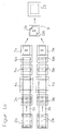
- FIGS. 1 a, 1 b show by way of example a production line for carrying out the method according to the invention in a side view and a top view:
- the embodiment shows a 2-wire production line in which two sheets 1a, 1b are processed in parallel.
- a coil 2a, 2b unraveled band-shaped sheets 1a, 1b are fed after straightening in each case a roller leveler 3a, 3b embossing stations 4a, 4b, which introduce the channel profile for the refrigerant by embossing in both sheets.
- a roller leveler 3a, 3b embossing stations 4a, 4b which introduce the channel profile for the refrigerant by embossing in both sheets.
- embossing stations 4a or 4b can be omitted; In this case, a flat sheet is joined together with an embossed sheet.
- the adhesive is applied in both strands, each with a roller 5a, 5b arranged above the strip run. Only after the adhesive has been rolled up are the band-shaped sheets 1a, 1b cut with scissors 6a, 6b into cutting stations 7a, 7b to the size of the evaporator plate 8 to be produced.
- the produced in the two parallel production lines and cut to size of the evaporator plate sheets 1a, 1b are brought together in a pressing tool 9 and at two points 11a, 11b by clinching fixed in a position effective in the sheet plane positive connection 12 in position to each other.
- the so fixed evaporator plates leave the pressing tool 9 immediately and get into a curing station 13 in which they harden under the pressure of a press 14 and simultaneous application of heat batchwise to the required final adhesive strength.
- Between the curing evaporator plates 8 are elastic intermediate layers 15, which prevent damage to both sides pronounced coolant channels in the curing station 13. If the capacity of the curing station 13 can not absorb all the evaporators 8 that can be produced from the two coils 2a, 2b, a plurality of curing stations can be provided to secure a continuous production flow.
- the transport of the sheets 1a, 1b between the cutting stations 7a, 7b, the pressing tool 9 and the curing station 13 advantageously takes place automatically, for example by means not shown in the figures for reasons of clarity funding and clocked gripping and lifting devices.
Abstract
Description
Die Erfindung betrifft eine Verdampferplatte für eine Kältemaschine mit zwischen zwei aufeinanderliegenden Blechen angeordneten Kältemittelkanälen sowie ein Verfahren zum Herstellen von Verdampferplatten.The invention relates to an evaporator plate for a refrigerator with arranged between two superimposed sheets of refrigerant channels and a method for producing evaporator plates.
Verdampferplatten sind ein Bestandteil einer Kältemaschine, in dem das flüssige Kältemittel unter Wärmeaufnahme aus der Umgebung verdampft wird. Kältemaschinen sind ortsfeste oder bewegliche Einrichtungen zur Kühlung von geschlossenen Räumen und von festen, flüssigen oder gasförmigen Körpern auf eine Temperatur unter derjenigen der Umgebung.Evaporator plates are part of a refrigerator in which the liquid refrigerant is evaporated while absorbing heat from the environment. Chillers are stationary or mobile devices for cooling closed spaces and solid, liquid or gaseous bodies to a temperature below that of the environment.
Verdampferplatten werden nach dem Stand der Technik hergestellt, indem verzinktes Aluminiumblech zunächst gerichtet und anschließend auf die gewünschte Größe der Verdampferplatte zugeschnitten wird. Auf die zugeschnittenen Bleche wird ein Trennmittel, z.B. Graphit, als Abbild des Kanalverlaufs für das Kältemittel in der Verdampferplatte aufgetragen. Anschließend werden zwei Platten zusammengelegt und unter Wärmezufuhr in einer Heizeinrichtung verpresst, so dass die beiden Bleche verlöten. Sodann werden die nicht verlöteten Kanalbereiche in einem Formwerkzeug beispielsweise mit Stickstoff aufgeblasen.Evaporator plates are manufactured according to the state of the art by first directing galvanized aluminum sheet and then cutting it to the desired size of the evaporator plate. On the cut sheets, a release agent, e.g. Graphite, applied as an image of the channel profile for the refrigerant in the evaporator plate. Subsequently, two plates are put together and pressed under heat in a heating device, so that the two plates soldered. Then, the non-soldered channel areas are inflated in a mold, for example, with nitrogen.
Darüber hinaus ist aus einem Prospekt der Fa. SHOWA ALUMINIUM CORPORATION, Osaka, Japan - 1993 ein sogenanntes Roll-Bond Verfahren bekannt, bei dem die aufeinanderliegenden Bleche nicht verlötet, sondern durch Heißwalzen miteinander verschweißt und anschließend auf Enddicke kalt ausgewalzt werden. Die durch das im Siebdruckverfahren aufgetragene Trennmittel von der Verschweißung ausgenommenen Kanalbereiche werden mit Druckluft aufgeblasen, bevor die Bleche in die einzelnen Verdampferplatten unterteilt werden. Nachteilig bei diesem Verfahren ist die Blechdickenänderung beim Heißwalzen und in dem nachgeordneten Kaltwalzschritt, da sie unmittelbar zu entsprechenden Blechlängenänderungen führen. Hieraus resultieren Probleme, die in nachfolgenden Arbeitsschritten zu einem hohen Ausschuss führen.In addition, from a brochure of the company SHOWA ALUMINUM CORPORATION, Osaka, Japan - 1993, a so-called roll-bonding method is known in which the stacked sheets not soldered, but welded together by hot rolling and then cold rolled to final thickness. The segregated by the screen-printed release agent from the welding channel sections are inflated with compressed air before the sheets are divided into the individual evaporator plates. A disadvantage of this method is the change in sheet thickness during hot rolling and in the downstream cold rolling step, since they lead directly to corresponding changes in sheet length. This results in problems that lead to high rejects in subsequent work steps.
Die nach den bekannten Verfahren hergestellten Verdampferplatten müssen aus Reinaluminium (A1 99,5) hergestellt werden, um das Einbringen der Kältemittelkanäle zu ermöglichen.The evaporator plates produced by the known methods must be made of pure aluminum (A1 99.5) to allow the introduction of the refrigerant channels.
Ausgehend von diesem Stand der Technik liegt der Erfindung daher die Aufgabe zugrunde eine Verdampferplatte zu schaffen, die nicht notwendigerweise aus Reinaluminium bestehen muss und dennoch einfach in großer Stückzahl herstellbar ist. Weiter liegt der Erfindung die Aufgabe zugrunde, ein Verfahren zur einfachen Serienfertigung von Verdampferplatten mit geringem Ausschuss vorzuschlagen, dass zugleich weniger Energie benötigt und mehr Gestaltungsspielraum hinsichtlich der Kältemittelkanalgeometrie eröffnet.Based on this prior art, the present invention is therefore an object of the invention to provide an evaporator plate, which does not necessarily have to consist of pure aluminum and yet is easy to produce in large quantities. It is a further object of the invention to propose a method for the simple series production of evaporator plates with a small scrap, which at the same time requires less energy and opens up more freedom of design with regard to the coolant channel geometry.
Der Erfindung zu Grunde liegende Gedanke besteht darin, dass die Verdampferplatte bildenden Bleche nicht wie bisher durch einen Lötvorgang oder einen Heißwalzprozess (Druck-Schweißen) gefügt werden, sondern mittels eines Klebstoffes miteinander verbunden sind, wobei Klebstoffe zum Einsatz gelangen, die beständig gegen Kältemittel sind und zumindest im Temperaturbereich zwischen - 30° C und + 40° C ihre Klebeeigenschaften beibehalten.The idea underlying the invention is that the sheets forming the evaporator plate are not joined as before by a soldering process or a hot rolling process (pressure welding), but are connected to one another by means of an adhesive, using adhesives which are resistant to refrigerants and at least in the Temperature range between - 30 ° C and + 40 ° C maintain their adhesive properties.
Als Klebstoffe kommen insbesondere Einkomponenten- oder Zweikomponenten-Klebstoffe zum Einsatz. Als besonders geeignet haben sich Zweikomponenten-Polyurethan Klebstoffe und Einkomponenten-Epoxydharz-Klebstoffe sowie temperaturabhängige Polyurethan- und Polyamid-Hotmelt Klebstoffe herausgestellt, wobei die Schichtdicke des Klebstoffs vorzugsweise im Bereich von 0,1 mm bis - 1,45 mm liegt. Die Hotmelt-Klebstoffe werden nicht erst nach der Formgebung des Kanals aufgetragen, sondern bereits auf dem insbesondere bandförmigen Ausgangsmaterial der Verdampferplatte. Derart beschichtete Bänder können wie unbeschichtete zum Coil gewickelt werden, ohne miteinander zu verkleben. Die Klebwirkung setzt erst nach Erwärmen auf eine bestimmte Temperatur ein.As adhesives in particular one-component or two-component adhesives are used. Two-component polyurethane adhesives and one-component epoxy resin adhesives and temperature-dependent polyurethane and polyamide hotmelt adhesives have proven to be particularly suitable, the layer thickness of the adhesive preferably being in the range from 0.1 mm to 1.45 mm. The hotmelt adhesives are applied not only after the shaping of the channel, but already on the particular band-shaped starting material of the evaporator plate. Such coated tapes can be wound like uncoated to the coil without sticking together. The adhesive effect begins only after heating to a certain temperature.
Das Fügen der Bleche durch einen Klebstoff erlaubt den Einsatz von Blechen mit Enddicke und Endfestigkeit, was sich vorteilhaft auf die Maßhaltigkeit der Verdampferplatten bei gleichzeitig verringerter Ausschussrate auswirkt. Der Energie-Einsatz ist beim Verkleben gegenüber den bisherigen, Verbindungstechniken erheblich reduziert. Zum flächigen Aufbringen auf die Fügeflächen kann der Klebstoff mit Walzen aufgerollt oder mit einem rakel- oder spachtelähnlichen Werkzeug aufgestrichen werden. Alternativ zum flächigen Auftragen kann der Klebstoff auch in Bahnen aufgespritzt werden, wobei die Menge so dosiert wird, dass nach dem Fügen der zu verklebenden Bleche kein überschüssiger Kleber in die Kältemittelkanäle eindringt.The joining of the sheets by an adhesive allows the use of sheets with final thickness and final strength, which has an advantageous effect on the dimensional stability of the evaporator plates at the same time reduced reject rate. The use of energy is significantly reduced in bonding compared to the previous, bonding techniques. For surface application to the joint surfaces of the adhesive can be rolled up with rollers or brushed with a squeegee or spatula-like tool. As an alternative to surface application, the adhesive can also be sprayed into webs, the amount being metered so that no excess adhesive penetrates into the coolant channels after joining the sheets to be bonded.
Wenn die Kältemittelkanäle im Wege des Kalt-Umformens, insbesondere durch Tiefziehen oder Prägen, eingebracht werden, lässt sich eine hohe Querschnittswiederholgenauigkeit sowie eine flexible Anordnung der Kältemittelkanäle in den aufeinanderliegenden Blechen der Verdampferplatte, wahlweise einseitig, beidseitig oder wechselseitig erreichen.If the refrigerant channels are introduced by means of cold forming, in particular by deep-drawing or embossing, a high cross-sectional repeatability and a flexible arrangement of the refrigerant channels in the superimposed sheets of the evaporator plate, either one-sided, bilateral or reciprocal can be achieved.
Das Einbringen der Kältemittelkanäle durch Tiefziehen oder Prägen ermöglicht den Einsatz von Aluminiumlegierungen bei der Herstellung von Verdampferplatten anstelle des bisher verwendeten Reinaluminiums. Weist die Aluminiumlegierung eine Zugfestigkeit von mindestens 200 N / mm2 auf, lässt sich eine erhebliche Materialeinsparung bei der Herstellung der Verdampferplatten erzielen. Trotz des Einsatzes von Blechen geringerer Dicke lassen sich die selben Druck- und Berstfestigkeiten der Verdampferplatte erzielen. Geeignete Aluminiumlegierungen sind beispielsweise die nachfolgend genannten Aluminium-Knetlegierungen:
- Al Mg 3
- Al Mg Si 1 oder
- Al Cu Mg 1.
- Al Mg 3
- Al Mg Si 1 or
- Al Cu Mg 1.
Die vorgenannten Legierungen weisen eine Zugfestigkeit im Bereich von 200 N / mm 2 bis 250 N / mm2 und eine Bruchdehnung von 12 % bis 15 % auf. Der Einsatz dieser Legierungen ermöglicht Blechdicken von weniger als 0,6 mm.The aforementioned alloys have a tensile strength in the range of 200 N / mm 2 to 250 N / mm 2 and an elongation at break of 12% to 15%. The use of these alloys allows sheet thicknesses of less than 0.6 mm.
In vorteilhafter Ausgestaltung der Erfindung werden zumindest die zu verklebenden Flächen der Bleche einer mechanischen und / oder thermischen Oberflächenbehandlung unterzogen. Abhängig von der verwendeten Aluminiumlegierung für die Bleche und dem verwendeten Kleber empfiehlt sich eine Oberflächenbehandlung, insbesondere eine chromfreie Beizassivierung für Aluminium, die im Tauch- oder Spritzverfahren aufgebracht wird. Die derart erzeugte Oxydationsschicht vermeidet unkontrollierte Oxydationen der verarbeiteten Bleche. Zusätzlich oder alternativ können weitere mechanische und / oder thermische Oberflächenbehandlungen der zu verklebenden Flächen durchgeführt werden. Mechanische Oberflächenbehandlungen (z.B. Bürsten) entfernen Verschmutzungen und rauen die Oberfläche auf, was sich bei bestimmten Klebstoffen vorteilhaft auf die Festigkeit der Klebeverbindung auswirken kann. Die thermische Oberflächenbehandlung entfettet die Oberfläche.In an advantageous embodiment of the invention, at least the surfaces of the sheets to be bonded are subjected to a mechanical and / or thermal surface treatment. Depending on the aluminum alloy used for the sheets and the used adhesive is recommended a surface treatment, in particular a chromium-free pickling for aluminum, which is applied by dipping or spraying. The oxidation layer thus produced avoids uncontrolled oxidations of the processed sheets. Additionally or alternatively, further mechanical and / or thermal surface treatments of the surfaces to be bonded can be carried out. Mechanical surface treatments (eg brushing) remove soiling and rough the surface, which may be advantageous for certain adhesives on the strength of the adhesive bond. The thermal surface treatment degreases the surface.
Je nach den Aushärtebedingungen und der Konsistenz des verwendeten Klebstoffs ist es zweckmäßig, dass die zusammengefügten und auf Verdampferplattengröße geschnitten Bleche bis zum Erreichen einer Mindestaushärtung des Klebers mechanisch zueinander fixiert werden. Um eine Presse hierfür nicht unvertretbar lange mit einer Verdampferplatte zu blockieren, kann im Presswerkzeug an mehreren auf die Verdampferplattenfläche gleichmäßig verteilten Stellen mittels Durchsetzfügen (Clinchen) eine in der Plattenebene wirksame formschlüssige Verbindung erzeugt werden, die die für die Kleberaushärtung erforderliche Fixierung aufrechterhält. Die auf diese Weise fixierten Verdampferplatten können die Presse sofort wieder verlassen und falls erforderlich einen Aushärteofen durchlaufen oder unter normalen Umgebungsbedingungen bis zur geforderten Kleberendfestigkeit aushärten.Depending on the curing conditions and the consistency of the adhesive used, it is expedient that the assembled and cut to evaporator plate size sheets are mechanically fixed to each other until a minimum curing of the adhesive. In order not to block a press unreasonably long with an evaporator plate for this purpose, in the pressing tool at several points evenly distributed on the evaporator plate surface by clinching clinching an effective in the plate plane positive connection can be generated, which maintains the required for the adhesive curing fixation. The fixed in this way evaporator plates can leave the press immediately and if necessary go through a curing or curing under normal environmental conditions to the required final adhesive strength.
Je nach verwendetem Kleber kann es erforderlich sein, dass die derart mechanisch fixierten Bleche zusätzlich aufeinander gepresst und/oder erwärmt werden. Hierzu werden die Platten mit elastischen Zwischenlagen zu einem Stapel aufeinander gelegt, um dann unter dem Druck einer Presse und/oder gleichzeitiger Temperatureinwirkung die geforderte Zeit auszuhärten.Depending on the adhesive used, it may be necessary for the sheets mechanically fixed in this way to be pressed and / or heated in addition. For this, the plates are with elastic intermediate layers stacked on top of each other to then harden the required time under the pressure of a press and / or simultaneous application of temperature.
Nach abgeschlossener Aushärtung schließen sich eine etwaige Nachbearbeitung, wie beispielsweise Stanzen, Biegen, Bördeln und Lackieren, an.Upon completion of curing, any post-processing, such as stamping, bending, crimping and painting, will follow.
In den Figuren 1 a, 1b ist beispielhaft eine Fertigungsstraße zur Durchführung des erfindungsgemäßen Verfahrens in einer Seitenansicht und einer Draufsicht dargestellt:FIGS. 1 a, 1 b show by way of example a production line for carrying out the method according to the invention in a side view and a top view:
Das Ausführungsbeispiel zeigt eine 2-adrige Fertigungsstraße, in der parallel zwei Bleche 1a, 1b bearbeitet werden. Die jeweils von einem Coil 2a, 2b abgehaspelten bandförmigen Bleche 1a, 1b werden nach dem Richten in jeweils einer Rollenrichtmaschine 3a, 3b Prägestationen 4a, 4b zugeführt, die den Kanalverlauf für das Kältemittel durch Prägen in beide Bleche einbringen. Sollen die Kältemittelkanäle nur einseitig eingeprägt werden, kann eine der Prägestationen 4a oder 4b entfallen; in diese Fall wird ein ebenes Blech mit einem geprägten Blech zusammengefügt.The embodiment shows a 2-wire production line in which two
Anschließend erfolgt der Kleberauftrag in beiden Strängen mit jeweils einer oberhalb des Bandlaufs angeordneten Walze 5a, 5b. Erst nach dem Aufrollen des Klebers werden die bandförmigen Bleche 1a, 1b mit Scheren 6a, 6b in Schneidstationen 7a, 7b auf die Größe der herzustellenden Verdampferplatte 8 abgelängt.Subsequently, the adhesive is applied in both strands, each with a
Um eine Produktionseinschränkung durch das Aushärten des Klebstoffs in einer Presse zu vermeiden, werden die in den beiden parallel angeordneten Fertigungsstraßen hergestellten und auf Größe der Verdampferplatte abgelängten Bleche 1a, 1b in einem Presswerkzeug 9 zusammengebracht und an zwei Stellen 11a, 11b mittels Durchsetzfügen (Clinchen) in einer in der Blechebene wirksamen formschlüssigen Verbindung 12 in ihrer Position zueinander fixiert.To avoid a production restriction by the curing of the adhesive in a press, the produced in the two parallel production lines and cut to size of the
Die so fixierten Verdampferplatten verlassen das Presswerkzeug 9 sofort wieder und gelangen in eine Aushärtestation 13 in der sie unter dem Druck einer Presse 14 und gleichzeitiger Temperatureinwirkung chargenweise bis zur geforderten Klebstoffendfestigkeit aushärten. Zwischen den aushärtenden Verdampferplatten 8 befinden sich elastische Zwischenlagen 15, die eine Beschädigung der beidseitig ausgeprägten Kühlmittelkanäle in der Aushärtestation 13 verhindern. Wenn die Kapazität der Aushärtestation 13 nicht sämtliche aus den beiden Coils 2a, 2b herstellbaren Verdampfer 8 aufnehmen kann, können zur Sicherung eines kontinuierlichen Produktionsflusses mehrere Aushärtestationen vorgesehen sein.The so fixed evaporator plates leave the
Der Transport der Bleche 1a, 1b zwischen den Schneidstationen 7a, 7b, dem Presswerkzeug 9 und der Aushärtestation 13 erfolgt vorteilhafterweise automatisch, beispielsweise mittels in den Figuren aus Gründen der Übersichtlichkeit nicht dargestellten Fördermitteln und getakteten Greif- und Hebeeinrichtungen.The transport of the
Claims (13)
- An evaporator plate for a refrigerating machine having coolant channels situated between two sheets lying one on top of another, characterized in that the sheets (1a, 1b) are bonded to one another using an adhesive, which is resistant to coolant and maintains its adhesive properties at least in the temperature range between -30°C and + 40°C.
- The evaporator plate according to claim 1, characterized in that the adhesive faces of the sheets are surface treated.
- The evaporator plate according to claim 1 or 2, characterized in that the adhesive is a two-component polyurethane or a one-component epoxide resin adhesive.
- The evaporator plate according to one of claims 1 through 3, characterized in that the material of the sheets (1a, 1b) is an aluminum alloy having a tensile strength of at least 200 N/mm2.
- The evaporator plate according to one of claims 1 through 4, characterized in that the sheets (1a, 1b) have cold formed coolant channels.
- A method for producing evaporator plates, particularly according to claims 1 through 5, from two sheets (1a, 1b) lying one on top of another, the channel course for the coolant being introduced into at least one of the sheets (1a), characterized in that the two sheets (1a, 1b) are joined by an adhesive and an adhesive, which is resistant to coolant and maintains its adhesive properties at least in the temperature range between -30°C and +40°C, is used for joining.
- The method for producing evaporator plates according to claim 6, characterized in that after the sheets (1a, 1b) to be joined are straightened, the channel course for the coolant is introduced into at least one of the two sheets (1a) through deep drawing.
- The method for producing evaporator plates according to claim 6, characterized in that after the sheets (1a, 1b) to be joined are straightened, the channel course for the coolant is introduced into at least one of the two sheets (1a) through embossing.
- The method for producing evaporator plates according to one of claims 6 through 8, characterized in that the sheets (1a, 1b) are cut to evaporator plate size before or after the application of the adhesive.
- The method for producing evaporator plates according to one of claims 6 through 9, characterized in that a temperature-dependent adhesive is applied flatly to both sheets (1a, 1b) before the channel course for the coolant is introduced into at least one of the two sheets (1a), the adhesive effect of the temperature-dependent adhesive first setting in after heating to a defined temperature.
- The method for producing evaporator plates according to one of claims 6 through 10, characterized in that at least one of the faces of the sheets (1a, 1b) to be glued is subjected to a mechanical and/or thermal surface treatment.
- The method for producing evaporator plates according to one of claims 6 through 11, characterized in that the joined sheets, which are cut to evaporator plate size, are fixed to one another until reaching a minimum curing of the adhesive.
- The method for producing evaporator plates according to claim 12, characterized in that the mechanically fixed sheets are additionally pressed on one another and/or heated.
Applications Claiming Priority (3)
| Application Number | Priority Date | Filing Date | Title |
|---|---|---|---|
| DE10100526 | 2001-01-08 | ||
| DE10100526 | 2001-01-08 | ||
| PCT/EP2001/011754 WO2002053371A1 (en) | 2001-01-08 | 2001-10-11 | Method of producing evaporator boards |
Publications (2)
| Publication Number | Publication Date |
|---|---|
| EP1349726A1 EP1349726A1 (en) | 2003-10-08 |
| EP1349726B1 true EP1349726B1 (en) | 2006-09-13 |
Family
ID=7669958
Family Applications (1)
| Application Number | Title | Priority Date | Filing Date |
|---|---|---|---|
| EP01272625A Expired - Lifetime EP1349726B1 (en) | 2001-01-08 | 2001-10-11 | Method of producing evaporator boards |
Country Status (9)
| Country | Link |
|---|---|
| US (1) | US20040091735A1 (en) |
| EP (1) | EP1349726B1 (en) |
| AT (1) | ATE339302T1 (en) |
| CA (1) | CA2434073A1 (en) |
| DE (1) | DE50111025D1 (en) |
| DK (1) | DK1349726T3 (en) |
| ES (1) | ES2272412T3 (en) |
| PT (1) | PT1349726E (en) |
| WO (1) | WO2002053371A1 (en) |
Cited By (1)
| Publication number | Priority date | Publication date | Assignee | Title |
|---|---|---|---|---|
| EP2508833A2 (en) | 2011-04-05 | 2012-10-10 | Flamm AG | Evaporator plate for a cooling machine |
Families Citing this family (2)
| Publication number | Priority date | Publication date | Assignee | Title |
|---|---|---|---|---|
| DE10306930B3 (en) * | 2003-02-19 | 2004-10-14 | Flamm Ag | Absorber for a thermal collector of a solar system and method for its production |
| KR100712916B1 (en) * | 2005-11-10 | 2007-05-02 | 엘지전자 주식회사 | Linear compressor |
Family Cites Families (21)
| Publication number | Priority date | Publication date | Assignee | Title |
|---|---|---|---|---|
| GB1061069A (en) * | 1964-11-27 | 1967-03-08 | Polyventions Ltd | Improvements in or relating to the manufacture of sheet metal central heating radiators |
| SE302105B (en) * | 1966-02-11 | 1968-07-08 | Svenska Metallverken Ab | |
| DE1601216B2 (en) * | 1967-11-03 | 1971-06-16 | Linde Ag, 6200 Wiesbaden | TIN PANEL FOR PLATE HEAT EXCHANGER WITH A STACK OF SUCH TIN PANELS |
| US3810509A (en) * | 1971-10-15 | 1974-05-14 | Union Carbide Corp | Cross flow heat exchanger |
| IT1039601B (en) * | 1975-10-07 | 1979-12-10 | Boston Spa | PRODUCT TO PROTECT AND CONNECT BIO-THERMAL SCA SURFACES BETWEEN LORD EQUAL AND RELATED APPLICATION PROCEDURE |
| JPS53111558A (en) * | 1977-03-10 | 1978-09-29 | Daicel Chem Ind Ltd | Cooler |
| DE2738670C2 (en) * | 1977-08-26 | 1979-10-25 | Unilever N.V., Rotterdam (Niederlande) | Plate heat exchanger |
| JPS599332A (en) * | 1982-07-06 | 1984-01-18 | Bridgestone Corp | Vibration damping material |
| DE3243713C2 (en) * | 1982-11-26 | 1985-05-15 | Fr. Kammerer GmbH, 7530 Pforzheim | Flat heat exchanger plate and process for their manufacture |
| JPS61186164A (en) * | 1985-02-15 | 1986-08-19 | Sanden Corp | Production of aluminum heat exchanger |
| US4758385A (en) * | 1987-06-22 | 1988-07-19 | Norsaire Systems | Plate for evaporative heat exchanger and evaporative heat exchanger |
| BE1002073A4 (en) * | 1988-05-26 | 1990-06-19 | Asturienne Mines Comp Royale | Standing structures elements. |
| EP0473843B1 (en) * | 1990-09-05 | 1995-07-26 | Fokker Aircraft B.V. | Laminate for bent structure as well as method for its production |
| JP2697400B2 (en) * | 1991-08-28 | 1998-01-14 | 日本軽金属株式会社 | Aluminum alloy for forging |
| US5644841A (en) * | 1994-08-19 | 1997-07-08 | Heatcraft Inc. | Method for manufacturing a heat transfer coil |
| EP0703427B1 (en) * | 1994-09-21 | 1999-07-28 | Showa Aluminum Corporation | Roll-bonded panel and process for producing roll-bonded panels |
| JP3212479B2 (en) * | 1995-03-31 | 2001-09-25 | 株式会社神戸製鋼所 | Plate fin heat exchanger and method of manufacturing the same |
| FR2748956B1 (en) * | 1996-05-24 | 1998-06-26 | Lorraine Laminage | METAL TANK FOR LIQUID |
| IT1289400B1 (en) * | 1996-11-26 | 1998-10-02 | Electrolux Zanussi Elettrodome | METHOD TO PRODUCE A HEAT EXCHANGER FOR A REFRIGERANT AND HEAT EXCHANGER SO PRODUCED |
| US5937519A (en) * | 1998-03-31 | 1999-08-17 | Zero Corporation | Method and assembly for manufacturing a convoluted heat exchanger core |
| FR2794227B1 (en) * | 1999-05-26 | 2001-08-31 | Valeo Thermique Moteur Sa | HEAT EXCHANGER WITH GLUE TUBES, PARTICULARLY FOR A MOTOR VEHICLE, AND METHOD FOR THE PRODUCTION THEREOF |
-
2001
- 2001-10-11 CA CA002434073A patent/CA2434073A1/en not_active Abandoned
- 2001-10-11 PT PT01272625T patent/PT1349726E/en unknown
- 2001-10-11 US US10/250,610 patent/US20040091735A1/en not_active Abandoned
- 2001-10-11 WO PCT/EP2001/011754 patent/WO2002053371A1/en active IP Right Grant
- 2001-10-11 DK DK01272625T patent/DK1349726T3/en active
- 2001-10-11 AT AT01272625T patent/ATE339302T1/en not_active IP Right Cessation
- 2001-10-11 EP EP01272625A patent/EP1349726B1/en not_active Expired - Lifetime
- 2001-10-11 DE DE50111025T patent/DE50111025D1/en not_active Expired - Fee Related
- 2001-10-11 ES ES01272625T patent/ES2272412T3/en not_active Expired - Lifetime
Cited By (3)
| Publication number | Priority date | Publication date | Assignee | Title |
|---|---|---|---|---|
| EP2508833A2 (en) | 2011-04-05 | 2012-10-10 | Flamm AG | Evaporator plate for a cooling machine |
| DE102011001804A1 (en) | 2011-04-05 | 2012-10-11 | Flamm Ag | Evaporator plate for a chiller |
| EP2508833A3 (en) * | 2011-04-05 | 2014-05-07 | FLAMM GmbH | Evaporator plate for a cooling machine |
Also Published As
| Publication number | Publication date |
|---|---|
| ES2272412T3 (en) | 2007-05-01 |
| DE50111025D1 (en) | 2006-10-26 |
| WO2002053371A1 (en) | 2002-07-11 |
| PT1349726E (en) | 2007-01-31 |
| US20040091735A1 (en) | 2004-05-13 |
| DK1349726T3 (en) | 2006-10-09 |
| ATE339302T1 (en) | 2006-10-15 |
| EP1349726A1 (en) | 2003-10-08 |
| CA2434073A1 (en) | 2002-07-11 |
Similar Documents
| Publication | Publication Date | Title |
|---|---|---|
| EP2432605A1 (en) | Method for producing a metal component from a hot-stamped raw material | |
| DE102009052210A1 (en) | Method for producing components with regions of different ductility | |
| DE10246164A1 (en) | Making e.g. vehicle structural components with wall thickness varied by rolling, shapes and hardens components through combination of heat- and mechanical treatments | |
| EP0423500A2 (en) | Method of fabricating a flat condenser for a refrigeration machine, in particular for a household refrigerator, and the flat condenser thereof | |
| DE4416147C2 (en) | Application of the hydroforming process for producing a curved metallic longitudinal hollow body and a hydroforming press that can be used for this purpose | |
| EP1349726B1 (en) | Method of producing evaporator boards | |
| EP2508833A2 (en) | Evaporator plate for a cooling machine | |
| EP1606565B1 (en) | Absorber for a thermal collector of a solar system and method for the production thereof | |
| EP0010618B1 (en) | Method of making a flat heat exchanger of sheet metal | |
| US3206839A (en) | Fabrication of heat exchangers | |
| DE19652744C3 (en) | Process for the production of profiled strips and profiled sheets, and profiled strips and profiled sheets produced thereafter | |
| DE3200631C2 (en) | ||
| DE19752201B4 (en) | Method and device for joining by forming | |
| DE102018124552A1 (en) | HOT-MOLDED CONNECTION IN LEAD PLATES | |
| WO2017153045A1 (en) | Method for producing a cast metal part, in particular a housing of an electric motor stator, a housing for components of power electronics, a battery tray or a battery housing, cast part produced using the method, and use of a cooling channel produced by roll welding | |
| DE102020206441A1 (en) | Process for the production of a multi-part cooling plate | |
| DE941604C (en) | Process for the formation of line connections on plate-shaped heat exchangers, especially plate evaporators for cooling systems | |
| DE2714905C3 (en) | Two-stage expansion of channel plates | |
| DE2431081B1 (en) | Roll weld cladding | |
| DE1577075C3 (en) | Process for producing a composite body from stainless steel and aluminum or an aluminum alloy | |
| WO2017021503A1 (en) | Method for producing a heat exchanger and heat exchanger | |
| WO2017021152A1 (en) | Method for producing a stacked-plate cooler, and stacked-plate cooler | |
| DE19756487A1 (en) | Heat exchange plate | |
| DE2616586A1 (en) | Pipe fittings for channel sheets - made by roll bonding and expanding two sheets which are then cut to make the individual fittings | |
| DE3331619C2 (en) |
Legal Events
| Date | Code | Title | Description |
|---|---|---|---|
| PUAI | Public reference made under article 153(3) epc to a published international application that has entered the european phase |
Free format text: ORIGINAL CODE: 0009012 |
|
| 17P | Request for examination filed |
Effective date: 20030516 |
|
| AK | Designated contracting states |
Kind code of ref document: A1 Designated state(s): AT BE CH CY DE DK ES FI FR GB GR IE IT LI LU MC NL PT SE TR |
|
| AX | Request for extension of the european patent |
Extension state: AL LT LV MK RO SI |
|
| 17Q | First examination report despatched |
Effective date: 20050613 |
|
| GRAP | Despatch of communication of intention to grant a patent |
Free format text: ORIGINAL CODE: EPIDOSNIGR1 |
|
| GRAS | Grant fee paid |
Free format text: ORIGINAL CODE: EPIDOSNIGR3 |
|
| GRAA | (expected) grant |
Free format text: ORIGINAL CODE: 0009210 |
|
| PGFP | Annual fee paid to national office [announced via postgrant information from national office to epo] |
Ref country code: DE Payment date: 20060901 Year of fee payment: 6 |
|
| AK | Designated contracting states |
Kind code of ref document: B1 Designated state(s): AT BE CH CY DE DK ES FI FR GB GR IE IT LI LU MC NL PT SE TR |
|
| PG25 | Lapsed in a contracting state [announced via postgrant information from national office to epo] |
Ref country code: IT Free format text: LAPSE BECAUSE OF FAILURE TO SUBMIT A TRANSLATION OF THE DESCRIPTION OR TO PAY THE FEE WITHIN THE PRESCRIBED TIME-LIMIT;WARNING: LAPSES OF ITALIAN PATENTS WITH EFFECTIVE DATE BEFORE 2007 MAY HAVE OCCURRED AT ANY TIME BEFORE 2007. THE CORRECT EFFECTIVE DATE MAY BE DIFFERENT FROM THE ONE RECORDED. Effective date: 20060913 Ref country code: FI Free format text: LAPSE BECAUSE OF FAILURE TO SUBMIT A TRANSLATION OF THE DESCRIPTION OR TO PAY THE FEE WITHIN THE PRESCRIBED TIME-LIMIT Effective date: 20060913 Ref country code: IE Free format text: LAPSE BECAUSE OF FAILURE TO SUBMIT A TRANSLATION OF THE DESCRIPTION OR TO PAY THE FEE WITHIN THE PRESCRIBED TIME-LIMIT Effective date: 20060913 |
|
| REG | Reference to a national code |
Ref country code: GB Ref legal event code: FG4D Free format text: NOT ENGLISH |
|
| PGFP | Annual fee paid to national office [announced via postgrant information from national office to epo] |
Ref country code: GR Payment date: 20060929 Year of fee payment: 6 |
|
| REG | Reference to a national code |
Ref country code: CH Ref legal event code: EP |
|
| REG | Reference to a national code |
Ref country code: DK Ref legal event code: T3 |
|
| REG | Reference to a national code |
Ref country code: SE Ref legal event code: TRGR |
|
| GBT | Gb: translation of ep patent filed (gb section 77(6)(a)/1977) |
Effective date: 20060914 |
|
| REG | Reference to a national code |
Ref country code: IE Ref legal event code: FG4D Free format text: LANGUAGE OF EP DOCUMENT: GERMAN |
|
| PGFP | Annual fee paid to national office [announced via postgrant information from national office to epo] |
Ref country code: GB Payment date: 20061024 Year of fee payment: 6 |
|
| REF | Corresponds to: |
Ref document number: 50111025 Country of ref document: DE Date of ref document: 20061026 Kind code of ref document: P |
|
| PG25 | Lapsed in a contracting state [announced via postgrant information from national office to epo] |
Ref country code: MC Free format text: LAPSE BECAUSE OF NON-PAYMENT OF DUE FEES Effective date: 20061031 Ref country code: CH Free format text: LAPSE BECAUSE OF NON-PAYMENT OF DUE FEES Effective date: 20061031 Ref country code: LI Free format text: LAPSE BECAUSE OF NON-PAYMENT OF DUE FEES Effective date: 20061031 |
|
| PGFP | Annual fee paid to national office [announced via postgrant information from national office to epo] |
Ref country code: AT Payment date: 20061031 Year of fee payment: 6 Ref country code: IT Payment date: 20061031 Year of fee payment: 6 Ref country code: NL Payment date: 20061031 Year of fee payment: 6 |
|
| PGFP | Annual fee paid to national office [announced via postgrant information from national office to epo] |
Ref country code: ES Payment date: 20061123 Year of fee payment: 6 |
|
| PGFP | Annual fee paid to national office [announced via postgrant information from national office to epo] |
Ref country code: PT Payment date: 20061212 Year of fee payment: 6 |
|
| PGFP | Annual fee paid to national office [announced via postgrant information from national office to epo] |
Ref country code: DK Payment date: 20061213 Year of fee payment: 6 |
|
| REG | Reference to a national code |
Ref country code: GR Ref legal event code: EP Ref document number: 20060404018 Country of ref document: GR |
|
| REG | Reference to a national code |
Ref country code: PT Ref legal event code: SC4A Free format text: AVAILABILITY OF NATIONAL TRANSLATION Effective date: 20061205 |
|
| REG | Reference to a national code |
Ref country code: IE Ref legal event code: FD4D |
|
| REG | Reference to a national code |
Ref country code: ES Ref legal event code: FG2A Ref document number: 2272412 Country of ref document: ES Kind code of ref document: T3 |
|
| EN | Fr: translation not filed | ||
| REG | Reference to a national code |
Ref country code: CH Ref legal event code: PL |
|
| PLBE | No opposition filed within time limit |
Free format text: ORIGINAL CODE: 0009261 |
|
| STAA | Information on the status of an ep patent application or granted ep patent |
Free format text: STATUS: NO OPPOSITION FILED WITHIN TIME LIMIT |
|
| 26N | No opposition filed |
Effective date: 20070614 |
|
| BERE | Be: lapsed |
Owner name: FLAMM A.G. Effective date: 20061031 |
|
| PGFP | Annual fee paid to national office [announced via postgrant information from national office to epo] |
Ref country code: SE Payment date: 20060918 Year of fee payment: 6 |
|
| PG25 | Lapsed in a contracting state [announced via postgrant information from national office to epo] |
Ref country code: FR Free format text: LAPSE BECAUSE OF FAILURE TO SUBMIT A TRANSLATION OF THE DESCRIPTION OR TO PAY THE FEE WITHIN THE PRESCRIBED TIME-LIMIT Effective date: 20070518 |
|
| REG | Reference to a national code |
Ref country code: DK Ref legal event code: EBP |
|
| EUG | Se: european patent has lapsed | ||
| GBPC | Gb: european patent ceased through non-payment of renewal fee |
Effective date: 20071011 |
|
| NLV4 | Nl: lapsed or anulled due to non-payment of the annual fee |
Effective date: 20080501 |
|
| PG25 | Lapsed in a contracting state [announced via postgrant information from national office to epo] |
Ref country code: DE Free format text: LAPSE BECAUSE OF NON-PAYMENT OF DUE FEES Effective date: 20080501 Ref country code: LU Free format text: LAPSE BECAUSE OF NON-PAYMENT OF DUE FEES Effective date: 20061011 |
|
| PG25 | Lapsed in a contracting state [announced via postgrant information from national office to epo] |
Ref country code: AT Free format text: LAPSE BECAUSE OF NON-PAYMENT OF DUE FEES Effective date: 20071011 |
|
| PG25 | Lapsed in a contracting state [announced via postgrant information from national office to epo] |
Ref country code: GR Free format text: LAPSE BECAUSE OF NON-PAYMENT OF DUE FEES Effective date: 20061214 Ref country code: NL Free format text: LAPSE BECAUSE OF NON-PAYMENT OF DUE FEES Effective date: 20080501 Ref country code: DK Free format text: LAPSE BECAUSE OF NON-PAYMENT OF DUE FEES Effective date: 20071031 Ref country code: SE Free format text: LAPSE BECAUSE OF NON-PAYMENT OF DUE FEES Effective date: 20071012 |
|
| PG25 | Lapsed in a contracting state [announced via postgrant information from national office to epo] |
Ref country code: GB Free format text: LAPSE BECAUSE OF NON-PAYMENT OF DUE FEES Effective date: 20071011 Ref country code: CY Free format text: LAPSE BECAUSE OF FAILURE TO SUBMIT A TRANSLATION OF THE DESCRIPTION OR TO PAY THE FEE WITHIN THE PRESCRIBED TIME-LIMIT Effective date: 20060913 Ref country code: FR Free format text: LAPSE BECAUSE OF FAILURE TO SUBMIT A TRANSLATION OF THE DESCRIPTION OR TO PAY THE FEE WITHIN THE PRESCRIBED TIME-LIMIT Effective date: 20060913 |
|
| REG | Reference to a national code |
Ref country code: ES Ref legal event code: FD2A Effective date: 20071013 |
|
| PG25 | Lapsed in a contracting state [announced via postgrant information from national office to epo] |
Ref country code: ES Free format text: LAPSE BECAUSE OF NON-PAYMENT OF DUE FEES Effective date: 20071013 |
|
| REG | Reference to a national code |
Ref country code: PT Ref legal event code: MM4A Free format text: LAPSE DUE TO NON-PAYMENT OF FEES Effective date: 20090413 |
|
| PG25 | Lapsed in a contracting state [announced via postgrant information from national office to epo] |
Ref country code: BE Free format text: LAPSE BECAUSE OF FAILURE TO SUBMIT A TRANSLATION OF THE DESCRIPTION OR TO PAY THE FEE WITHIN THE PRESCRIBED TIME-LIMIT Effective date: 20061031 Ref country code: IT Free format text: LAPSE BECAUSE OF NON-PAYMENT OF DUE FEES Effective date: 20071011 |
|
| PG25 | Lapsed in a contracting state [announced via postgrant information from national office to epo] |
Ref country code: TR Free format text: LAPSE BECAUSE OF FAILURE TO SUBMIT A TRANSLATION OF THE DESCRIPTION OR TO PAY THE FEE WITHIN THE PRESCRIBED TIME-LIMIT Effective date: 20060913 |
|
| PG25 | Lapsed in a contracting state [announced via postgrant information from national office to epo] |
Ref country code: PT Free format text: LAPSE BECAUSE OF NON-PAYMENT OF DUE FEES Effective date: 20060913 |