EP1349136A1 - Signalling device - Google Patents
Signalling device Download PDFInfo
- Publication number
- EP1349136A1 EP1349136A1 EP03075476A EP03075476A EP1349136A1 EP 1349136 A1 EP1349136 A1 EP 1349136A1 EP 03075476 A EP03075476 A EP 03075476A EP 03075476 A EP03075476 A EP 03075476A EP 1349136 A1 EP1349136 A1 EP 1349136A1
- Authority
- EP
- European Patent Office
- Prior art keywords
- vehicle
- unit
- signalling
- signalling device
- message
- Prior art date
- Legal status (The legal status is an assumption and is not a legal conclusion. Google has not performed a legal analysis and makes no representation as to the accuracy of the status listed.)
- Withdrawn
Links
Images


Classifications
-
- B—PERFORMING OPERATIONS; TRANSPORTING
- B60—VEHICLES IN GENERAL
- B60Q—ARRANGEMENT OF SIGNALLING OR LIGHTING DEVICES, THE MOUNTING OR SUPPORTING THEREOF OR CIRCUITS THEREFOR, FOR VEHICLES IN GENERAL
- B60Q1/00—Arrangement of optical signalling or lighting devices, the mounting or supporting thereof or circuits therefor
- B60Q1/26—Arrangement of optical signalling or lighting devices, the mounting or supporting thereof or circuits therefor the devices being primarily intended to indicate the vehicle, or parts thereof, or to give signals, to other traffic
- B60Q1/50—Arrangement of optical signalling or lighting devices, the mounting or supporting thereof or circuits therefor the devices being primarily intended to indicate the vehicle, or parts thereof, or to give signals, to other traffic for indicating other intentions or conditions, e.g. request for waiting or overtaking
- B60Q1/503—Arrangement of optical signalling or lighting devices, the mounting or supporting thereof or circuits therefor the devices being primarily intended to indicate the vehicle, or parts thereof, or to give signals, to other traffic for indicating other intentions or conditions, e.g. request for waiting or overtaking using luminous text or symbol displays in or on the vehicle, e.g. static text
-
- B—PERFORMING OPERATIONS; TRANSPORTING
- B60—VEHICLES IN GENERAL
- B60Q—ARRANGEMENT OF SIGNALLING OR LIGHTING DEVICES, THE MOUNTING OR SUPPORTING THEREOF OR CIRCUITS THEREFOR, FOR VEHICLES IN GENERAL
- B60Q1/00—Arrangement of optical signalling or lighting devices, the mounting or supporting thereof or circuits therefor
- B60Q1/26—Arrangement of optical signalling or lighting devices, the mounting or supporting thereof or circuits therefor the devices being primarily intended to indicate the vehicle, or parts thereof, or to give signals, to other traffic
- B60Q1/50—Arrangement of optical signalling or lighting devices, the mounting or supporting thereof or circuits therefor the devices being primarily intended to indicate the vehicle, or parts thereof, or to give signals, to other traffic for indicating other intentions or conditions, e.g. request for waiting or overtaking
- B60Q1/549—Arrangement of optical signalling or lighting devices, the mounting or supporting thereof or circuits therefor the devices being primarily intended to indicate the vehicle, or parts thereof, or to give signals, to other traffic for indicating other intentions or conditions, e.g. request for waiting or overtaking for expressing greetings, gratitude or emotions
-
- G—PHYSICS
- G09—EDUCATION; CRYPTOGRAPHY; DISPLAY; ADVERTISING; SEALS
- G09F—DISPLAYING; ADVERTISING; SIGNS; LABELS OR NAME-PLATES; SEALS
- G09F21/00—Mobile visual advertising
- G09F21/04—Mobile visual advertising by land vehicles
-
- G—PHYSICS
- G09—EDUCATION; CRYPTOGRAPHY; DISPLAY; ADVERTISING; SEALS
- G09F—DISPLAYING; ADVERTISING; SIGNS; LABELS OR NAME-PLATES; SEALS
- G09F9/00—Indicating arrangements for variable information in which the information is built-up on a support by selection or combination of individual elements
- G09F9/30—Indicating arrangements for variable information in which the information is built-up on a support by selection or combination of individual elements in which the desired character or characters are formed by combining individual elements
- G09F9/33—Indicating arrangements for variable information in which the information is built-up on a support by selection or combination of individual elements in which the desired character or characters are formed by combining individual elements being semiconductor devices, e.g. diodes
Definitions
- the present invention relates to a signalling device, particularly, though not exclusively, for use in sending a message from one vehicle to a following one.
- the object of my invention is to provide a signalling device with which a driver can thank a following driver, bearing in mind that an articulated lorry is configured as a tractor and trailer, the driver often delivering one trailer and collecting another.
- a vehicle signalling device comprising:
- the transmitting unit and the signalling unit could be of the type requiring aerials, or indeed an infra-red emitter and receptor, which could be arranged close to each other at the front of the trailer and the rear of the tractor, with attendant wiring to the units as such, the transmitter and the receiver are preferably of the type requiring no external aerial, such as used in vehicle locking systems.
- the transmitting unit could be adapted to permanently attached in a cab of the vehicle. However, it is preferably removable, as with a sucker, hook and loop fastener or a self-adhesive pad. Conveniently it is provided with a single button for initiating the signal. Additionally, it can be provided with an indicator such as an LED to indicate that it is active.
- the signalling unit likewise could be permanently installed at the rear of the vehicle, or its trailer. However, it is preferably demountable, to allow the driver to remove it to another vehicle or trailer. Demounting can be by sucker, magnet, lashing or screw fastening.
- the unit has a viewing window with a series of LEDs arranged on a board within the window to spell the message such as: THANK YOU or MERCI BIEN or DANKE SCH ⁇ N. Both units can be adapted to be powered from the vehicle's electrical supply. However, they are preferably powered from internal batteries, facilitating transferability.
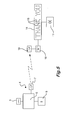
- the transmitting unit 1 of the signalling device comprises a small injection moulded case 2 having an operating button 3 and an indicating LED 4. Internally it accommodates a battery 5 and a PCB 6 embodying a transmitting circuit 7. The circuit will not be described in detail. It can be similar to that used for remote locking of vehicles. As shown, the case is provided with one side 8 of a hook and loop fastening. The other side 9 is affixed to the dashboard D or indeed the steering wheel W of the vehicle.
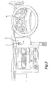
- the signalling unit 10 shown in Figures 3 & 4 has a casing 11 of pressed steel, with a transparent plastics material window 12 held on by a surround 13. Mounted within the window is a PCB 14 having LEDS 15 set out in the manner of the letters of THANK YOU. A receiving circuit 16 is mounted on the PCB. A battery 17 provides power to the LEDs in event of a signal from the transmitting unit. A timer circuit 18 maintains the power for 5 seconds.
- the casing is provided with attachment flanges 19 for fastening the unit to frame of the lorry at its rear, as by bolts and wing nuts 20.
- the lorry having the signalling device overtakes another who flashes to indicate room to pull in.
- the driver presses the operating button 3.
- the LED on the transmitting unit stays illuminated for 5 seconds.
- the transmitting circuit 7 initiates illumination of the THANK YOU LEDs for 5 seconds via the receiving circuit 16 and the timer 18.
- the signalling unit can be attached to the lorry by magnetic clamps 21 for instance.
Landscapes
- Engineering & Computer Science (AREA)
- Mechanical Engineering (AREA)
- Physics & Mathematics (AREA)
- General Physics & Mathematics (AREA)
- Theoretical Computer Science (AREA)
- Business, Economics & Management (AREA)
- Accounting & Taxation (AREA)
- Marketing (AREA)
- Lighting Device Outwards From Vehicle And Optical Signal (AREA)
Abstract
A device for signalling between vehicles is provided, having a transmitter for
mounting in a cab of the vehicle and for transmitting a wireless, message-initiating
signal. A remote unit is also provided for receiving the wireless, message-initiating
signal and a display for displaying a message in response to the signal. The device is
adapted to be moved with a driver from vehicle to vehicle. The message will
generally be THANK YOU, in English or any other language appropriate to the
country where the device is in use. The device may be powered from internal
batteries or the electrical supply of the vehicle.
Description
- The present invention relates to a signalling device, particularly, though not exclusively, for use in sending a message from one vehicle to a following one.
- It is known to signal as with a direction indicator. There have also been proposals to install message displays in the rear wind screen of cars. Police cars use such devices.
- Lorries, when overtaking have developed a habit of indicating once with one indicator and once with the other to say thank you to a following lorry who has just indicated with a head-light flash that the front lorry is clear to pull in after overtaking. In my experience, this can be confusing to other drivers, how may mistake this use of indicators to mean that the indicating lorry is about to pull out and overtake.
- The object of my invention is to provide a signalling device with which a driver can thank a following driver, bearing in mind that an articulated lorry is configured as a tractor and trailer, the driver often delivering one trailer and collecting another.
- Accordingly in my invention I provide a vehicle signalling device comprising:
- a transmitting unit adapted for mounting in a cab of the vehicle and having a transmitter to transmit a wireless, message-initiating signal and
- a remote signalling unit adapted for mounting at the rear of the vehicle and for displaying a visible message in response to a message-initiating signal and having a receiver to receive the message-initiating signal.
-
- Whilst it is envisaged that the transmitting unit and the signalling unit could be of the type requiring aerials, or indeed an infra-red emitter and receptor, which could be arranged close to each other at the front of the trailer and the rear of the tractor, with attendant wiring to the units as such, the transmitter and the receiver are preferably of the type requiring no external aerial, such as used in vehicle locking systems.
- The transmitting unit could be adapted to permanently attached in a cab of the vehicle. However, it is preferably removable, as with a sucker, hook and loop fastener or a self-adhesive pad. Conveniently it is provided with a single button for initiating the signal. Additionally, it can be provided with an indicator such as an LED to indicate that it is active.
- The signalling unit likewise could be permanently installed at the rear of the vehicle, or its trailer. However, it is preferably demountable, to allow the driver to remove it to another vehicle or trailer. Demounting can be by sucker, magnet, lashing or screw fastening. Preferably, the unit has a viewing window with a series of LEDs arranged on a board within the window to spell the message such as:
THANK YOU or MERCI BIEN or DANKE SCHÖN.
Both units can be adapted to be powered from the vehicle's electrical supply. However, they are preferably powered from internal batteries, facilitating transferability. - To help understanding of my invention, a specific embodiment thereof will now be described by way of example and with reference to the accompanying drawings, in which:
- Figure 1 is a perspective view of a transmitting unit of a signalling device of my invention;
- Figure 2 is a view of the transmitting unit installed in a lorry cab;
- Figure 3 is a perspective view of a signalling unit of the signalling device;
- Figure 4 is a similar view of the signalling unit installed at the rear of a lorry;
- Figure 5 is a block diagram of the circuitry of the signalling device.
-
- Referring first to Figures 1 and 2, the transmitting
unit 1 of the signalling device comprises a small injection mouldedcase 2 having anoperating button 3 and an indicatingLED 4. Internally it accommodates abattery 5 and aPCB 6 embodying a transmittingcircuit 7. The circuit will not be described in detail. It can be similar to that used for remote locking of vehicles. As shown, the case is provided with oneside 8 of a hook and loop fastening. Theother side 9 is affixed to the dashboard D or indeed the steering wheel W of the vehicle. - The
signalling unit 10 shown in Figures 3 & 4 has acasing 11 of pressed steel, with a transparentplastics material window 12 held on by asurround 13. Mounted within the window is aPCB 14 havingLEDS 15 set out in the manner of the letters of THANK YOU. Areceiving circuit 16 is mounted on the PCB. Abattery 17 provides power to the LEDs in event of a signal from the transmitting unit. Atimer circuit 18 maintains the power for 5 seconds. - The casing is provided with
attachment flanges 19 for fastening the unit to frame of the lorry at its rear, as by bolts andwing nuts 20. - In use, the lorry having the signalling device overtakes another who flashes to indicate room to pull in. The driver presses the
operating button 3. The LED on the transmitting unit stays illuminated for 5 seconds. The transmittingcircuit 7 initiates illumination of the THANK YOU LEDs for 5 seconds via thereceiving circuit 16 and thetimer 18. After delivery, if the lorry driver is required to deliver a different trailer elsewhere, it is a simple matter to remove the signalling unit, which is self contained and install it at the rear of the next trailer. - The invention is not intended to be restricted to the details of the above-described embodiment. For instance, the signalling unit can be attached to the lorry by
magnetic clamps 21 for instance.
Claims (18)
- A vehicle signalling device comprising:a transmitting unit adapted for mounting in a cab of the vehicle and having a transmitter to transmit a wireless, message-initiating signal anda remote signalling unit adapted for mounting at the rear of the vehicle and for displaying a visible message in response to a message-initiating signal and having a receiver to receive the message-initiating signal.
- A vehicle signalling device as claimed in claim 1, wherein the transmitter and the receiver are of the type requiring no external aerial, such as used in vehicle locking systems.
- A vehicle signalling device as claimed in claim 1, wherein the transmitting unit and the signalling unit are of the type requiring aerials.
- A vehicle signalling device as claimed in claim 1, wherein the transmitting unit is an infra-red emitter and the signalling unit is infra-red receptor.
- A vehicle signalling device as claimed in any preceding claim, wherein the transmitting device is moveable.
- A vehicle signalling device as claimed in claim 5, wherein the transmitting device is attachable to the vehicle by means of a sucker, hook and loop fastening, or a self-adhesive pad.
- A vehicle signalling device as claimed in any one of claims 1 to 4, wherein the transmitting unit is adapted to permanently attached in a cab of the vehicle.
- A vehicle signalling device as claimed in any preceding claim, wherein the transmitting unit is provided with a single button for initiating the signal.
- A vehicle signalling device as claimed in any preceding claim, wherein the transmitting unit is provided with an indicator to indicate that it is active.
- A vehicle signalling device as claimed in claim 9, wherein the indicator is an LED.
- A vehicle signalling device as claimed in any preceding claim, wherein the remote signalling unit is permanently installed at the rear of the vehicle or its trailer.
- A vehicle signalling device as claimed in any one of claim 1 to 9, wherein the remote signalling unit is demountable, to allow a driver to remove it to another vehicle or trailer.
- A vehicle signalling device as claimed in claim 11, wherein the fixing for demounting of the remote signalling unit is a sucker, magnet, lashing or screw fastening.
- A vehicle signalling device as claimed in any preceding claim, wherein remote signalling unit has a viewing window with a series of LEDs arranged on a board within the window to spell the message
- A vehicle signalling device as claimed in any preceding claim, wherein the message is:
THANK YOU or MERCI BIEN or DANKE SCHÖN. - A vehicle signalling device as claimed in any preceding claim, wherein both the transmitter unit and the remote signalling unit are powered from internal batteries.
- A vehicle signalling device as claimed in any one of claim 1 to 15, wherein both the transmitter unit and the remote signalling unit are adapted to be powered from the vehicle's electrical supply.
- A vehicle signalling device substantially as hereinbefore described with reference to Figures 1 to 5 of the accompanying drawings.
Applications Claiming Priority (2)
| Application Number | Priority Date | Filing Date | Title |
|---|---|---|---|
| GB0207039 | 2002-03-26 | ||
| GB0207039A GB2387011A (en) | 2002-03-26 | 2002-03-26 | Vehicle mounted matrix display comprising wireless link |
Publications (1)
| Publication Number | Publication Date |
|---|---|
| EP1349136A1 true EP1349136A1 (en) | 2003-10-01 |
Family
ID=9933683
Family Applications (1)
| Application Number | Title | Priority Date | Filing Date |
|---|---|---|---|
| EP03075476A Withdrawn EP1349136A1 (en) | 2002-03-26 | 2003-02-18 | Signalling device |
Country Status (2)
| Country | Link |
|---|---|
| EP (1) | EP1349136A1 (en) |
| GB (1) | GB2387011A (en) |
Cited By (3)
| Publication number | Priority date | Publication date | Assignee | Title |
|---|---|---|---|---|
| US7659808B1 (en) | 2006-08-21 | 2010-02-09 | Richard P Cooper | Automotive messaging display unit |
| CN103309504A (en) * | 2013-05-23 | 2013-09-18 | 中国矿业大学 | Touch screen input LED Chinese character display system with wireless communication function |
| CN113112782A (en) * | 2021-04-07 | 2021-07-13 | 深圳市丹芽科技有限公司 | Low-power-consumption wireless control method, transmitter and receiver |
Families Citing this family (2)
| Publication number | Priority date | Publication date | Assignee | Title |
|---|---|---|---|---|
| GB2440566A (en) * | 2006-08-01 | 2008-02-06 | Incorporating Courtesy Ltd | Vechicle message display |
| FR3063482A1 (en) * | 2017-03-01 | 2018-09-07 | Francois Arthur Georges Haquenne | SECURITY DISPLAY TWO WHEELS |
Citations (3)
| Publication number | Priority date | Publication date | Assignee | Title |
|---|---|---|---|---|
| EP0214594A2 (en) * | 1985-09-03 | 1987-03-18 | Gerald Clinker | Improved auxiliary vehicle warning system |
| GB2227590A (en) * | 1988-10-19 | 1990-08-01 | Timothy Charles Dodd | Vehicle message display system |
| GB2347004A (en) * | 1999-02-19 | 2000-08-23 | Paul Gillespie | Vehicle message display unit |
Family Cites Families (3)
| Publication number | Priority date | Publication date | Assignee | Title |
|---|---|---|---|---|
| DE3127941A1 (en) * | 1981-07-15 | 1983-02-03 | Fritz 7513 Stutensee Seeger | Electro-optical illuminated panel |
| US6195000B1 (en) * | 1993-02-19 | 2001-02-27 | Jack V. Smith | Emergency auto visual communication system |
| US5905434A (en) * | 1997-12-08 | 1999-05-18 | Steffan; Paul J. | Vehicle communication device |
-
2002
- 2002-03-26 GB GB0207039A patent/GB2387011A/en not_active Withdrawn
-
2003
- 2003-02-18 EP EP03075476A patent/EP1349136A1/en not_active Withdrawn
Patent Citations (3)
| Publication number | Priority date | Publication date | Assignee | Title |
|---|---|---|---|---|
| EP0214594A2 (en) * | 1985-09-03 | 1987-03-18 | Gerald Clinker | Improved auxiliary vehicle warning system |
| GB2227590A (en) * | 1988-10-19 | 1990-08-01 | Timothy Charles Dodd | Vehicle message display system |
| GB2347004A (en) * | 1999-02-19 | 2000-08-23 | Paul Gillespie | Vehicle message display unit |
Cited By (4)
| Publication number | Priority date | Publication date | Assignee | Title |
|---|---|---|---|---|
| US7659808B1 (en) | 2006-08-21 | 2010-02-09 | Richard P Cooper | Automotive messaging display unit |
| CN103309504A (en) * | 2013-05-23 | 2013-09-18 | 中国矿业大学 | Touch screen input LED Chinese character display system with wireless communication function |
| CN113112782A (en) * | 2021-04-07 | 2021-07-13 | 深圳市丹芽科技有限公司 | Low-power-consumption wireless control method, transmitter and receiver |
| CN113112782B (en) * | 2021-04-07 | 2022-09-16 | 深圳市艾斯龙科技有限公司 | Low-power-consumption wireless control method, transmitter and receiver |
Also Published As
| Publication number | Publication date |
|---|---|
| GB2387011A (en) | 2003-10-01 |
| GB0207039D0 (en) | 2002-05-08 |
Similar Documents
| Publication | Publication Date | Title |
|---|---|---|
| US4631516A (en) | Auxiliary vehicle warning system | |
| US7468656B1 (en) | Rear-end collision warning light system | |
| US7061402B1 (en) | Emergency vehicle warning system | |
| US5424715A (en) | Wireless taillight system | |
| US6239701B1 (en) | Vehicle locator light | |
| US20100308989A1 (en) | Wireless light and accessory control system for golf carts and other vehicles | |
| US10829038B1 (en) | Illuminated message display indicator system | |
| US20020080016A1 (en) | Vehicle safety monitoring system for viewing blind spots | |
| WO2003063453A3 (en) | A vehicular system having a warning system to alert motorists that a mobile phone is in use | |
| US20200001781A1 (en) | Warning message system for deterrence of tailgating | |
| US7641369B1 (en) | Emergency under-lighting systems for vehicles | |
| EP2788965A1 (en) | Vehicle data communication and display system | |
| EP1349136A1 (en) | Signalling device | |
| US7199705B1 (en) | Wireless tailgate lights | |
| US20170140683A1 (en) | Digital Display Screen Device | |
| GB2430787A (en) | Automatic ice warning road sign | |
| US9466211B1 (en) | Early warning system of emergency vehicles for alerting roadway traffic | |
| US6686849B1 (en) | Emergency vehicle proximity reporting system | |
| US20050018444A1 (en) | Illuminated hazard warning light | |
| US20120313793A1 (en) | Truck mounted stop light display | |
| US20070109145A1 (en) | Lighted display device with user selectable message | |
| US20190168665A1 (en) | Digital Display Screen Device | |
| US20040231209A1 (en) | Illuminated vehicle sign | |
| CN204821326U (en) | Car microwave radar anticollision early warning system based on video fuses | |
| JP2007050712A (en) | Monitoring device for surrounding area of vehicle |
Legal Events
| Date | Code | Title | Description |
|---|---|---|---|
| PUAI | Public reference made under article 153(3) epc to a published international application that has entered the european phase |
Free format text: ORIGINAL CODE: 0009012 |
|
| AK | Designated contracting states |
Kind code of ref document: A1 Designated state(s): AT BE BG CH CY CZ DE DK EE ES FI FR GB GR HU IE IT LI LU MC NL PT SE SI SK TR |
|
| AX | Request for extension of the european patent |
Extension state: AL LT LV MK RO |
|
| AKX | Designation fees paid | ||
| REG | Reference to a national code |
Ref country code: DE Ref legal event code: 8566 |
|
| STAA | Information on the status of an ep patent application or granted ep patent |
Free format text: STATUS: THE APPLICATION IS DEEMED TO BE WITHDRAWN |
|
| 18D | Application deemed to be withdrawn |
Effective date: 20040402 |