EP1349091A2 - LSI mask manufacturing system, LSI mask manufacturing method and LSI mask manufacturing program - Google Patents
LSI mask manufacturing system, LSI mask manufacturing method and LSI mask manufacturing program Download PDFInfo
- Publication number
- EP1349091A2 EP1349091A2 EP03006732A EP03006732A EP1349091A2 EP 1349091 A2 EP1349091 A2 EP 1349091A2 EP 03006732 A EP03006732 A EP 03006732A EP 03006732 A EP03006732 A EP 03006732A EP 1349091 A2 EP1349091 A2 EP 1349091A2
- Authority
- EP
- European Patent Office
- Prior art keywords
- lithography
- unit
- mask manufacturing
- user terminal
- data
- Prior art date
- Legal status (The legal status is an assumption and is not a legal conclusion. Google has not performed a legal analysis and makes no representation as to the accuracy of the status listed.)
- Granted
Links
Images










Classifications
-
- G—PHYSICS
- G03—PHOTOGRAPHY; CINEMATOGRAPHY; ANALOGOUS TECHNIQUES USING WAVES OTHER THAN OPTICAL WAVES; ELECTROGRAPHY; HOLOGRAPHY
- G03F—PHOTOMECHANICAL PRODUCTION OF TEXTURED OR PATTERNED SURFACES, e.g. FOR PRINTING, FOR PROCESSING OF SEMICONDUCTOR DEVICES; MATERIALS THEREFOR; ORIGINALS THEREFOR; APPARATUS SPECIALLY ADAPTED THEREFOR
- G03F1/00—Originals for photomechanical production of textured or patterned surfaces, e.g., masks, photo-masks, reticles; Mask blanks or pellicles therefor; Containers specially adapted therefor; Preparation thereof
- G03F1/68—Preparation processes not covered by groups G03F1/20 - G03F1/50
-
- G—PHYSICS
- G06—COMPUTING OR CALCULATING; COUNTING
- G06F—ELECTRIC DIGITAL DATA PROCESSING
- G06F30/00—Computer-aided design [CAD]
-
- G—PHYSICS
- G06—COMPUTING OR CALCULATING; COUNTING
- G06F—ELECTRIC DIGITAL DATA PROCESSING
- G06F2111/00—Details relating to CAD techniques
- G06F2111/04—Constraint-based CAD
Definitions
- the present invention relates to methods, systems and programs for manufacturing masks of a large scale integrated (LSI) system.
- LSI large scale integrated
- masks or reticles are needed to be produced depending on each semiconductor manufacturing process. Therefore, first, mask data, corresponding to each of a plural number of masks, are generated by using a computer-aided design (CAD) system based on design of an LSI. Then, masks that can be put on top of one another are generated by using a pattern generator, such as an electron beam writer, and a mask set is completed. Furthermore, each of the masks is checked. Finally, the masks, after the examination, are going to be used in a semiconductor manufacturing process.
- CAD computer-aided design
- customers such as semiconductor manufacturing makers and semiconductor foundry, specifies a mask specification, specific numbers, and delivery time to order masks to a mask house, and the mask house delivers masks before the delivery time.
- a schedule and machines such as pattern generators
- all the selection of a schedule and machines is entrusted to a decision of the mask manufacturing house side, where a customer is not able to choose any schedule or machines.
- An LSI mask manufacturing system includes: a network; a portal site server configured to be connected to the network; a user terminal configured to be connected to the portal site server; a host terminal configured to be connected to the network; and a lithography units configured to be connected to the host terminal.
- An LSI mask manufacturing system includes: a network; a portal site server configured to be connected to the network; a user terminal configured to connected to the portal site server; a host terminal configured to connected to the network; and a mask manufacturing unit configured to connected to the host terminal.
- a computer implemented method for LSI mask manufacturing includes : storing performance information of a lithography unit, connected to a network, in a lithography unit database; receiving a lithography data and a lithography reservation condition from a user terminal connected to the network; storing the lithography data in a lithography data database; searching for a lithography unit matching to the lithography reservation condition, generating a list of lithography units, and sending the list to the user terminal; and receiving information of a lithography unit specified by the user terminal and sending a lithography request to the lithography unit specified by the user terminal.
- a computer implemented method for LSI mask manufacturing includes: storing performance information of a mask manufacturing unit, connected to a network, in a mask manufacturing unit database; receiving data and a reservation condition from a user terminal connected to the network; storing the data in a mask manufacturing data database; determining a ordered range based on the reservation condition; searching for a mask manufacturing unit marching to the reservation condition, generating a list of mask manufacturing units, and sending the list to the user terminal; and receiving information of a mask manufacturing unit specified by the user terminal and sending a request to the mask manufacturing unit specified by the user terminal.
- a computer program product for use with a mask manufacturing unit includes: instructions to store performance information of a lithography unit, connected to a network, in a lithography unit database; instructions to receive a lithography data and a lithography reservation condition from a user terminal connected to the network; instructions to store the lithography data in a lithography data database; instructions to search for a lithography unit matching to the lithography reservation condition, generate a list of lithography units, and send the list to the user terminal; and instructions to receive information of a lithography unit specified by the user terminal and send a lithography request to the lithography unit specified by the user terminal.
- a computer program product for use with a mask manufacturing unit includes: instructions to store performance information of a mask manufacturing unit, connected to a network, in amaskmanufacturing unit database; instructions to receive data and a reservation condition from a user terminal connected to the network; instructions to store the data in a mask manufacturing data database; instructions to determine a ordered range based on the reservation condition; instructions to search for a mask manufacturing unit matching to the reservation condition, generate a list of mask manufacturing units, and send the list to the user terminal; and instructions to receive information of a mask manufacturing unit specified by the user terminal and send a request to the mask manufacturing unit specified by the user terminal.
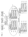
- FIG.1 is a conceptual diagram illustrating the LSI mask manufacturing system according to the first embodiment of the present invention.
- FIG.2 is a block diagram illustrating a portal site server 1 shown in FIG.1.
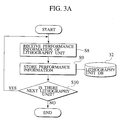
- FIG.3A and FIG.3B are flowcharts illustrating the LSI mask manufacturing method according to the first embodiment of the present invention.
- FIG.4 is a flowchart illustrating a lithography data forwarding process shown in FIG.3B.
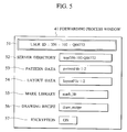
- FIG.5 is an example of the forwarding process window of the first embodiment of the present invention.
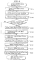
- FIG. 6 is a flowchart illustrating a lithography reservation process shown in FIG.3B.
- FIG.7 is an example of the lithography unit reservation window of the first embodiment of the present invention.
- FIG.8 is an example of the time prediction process window of the first embodiment of the present invention.
- FIG.9 is an example of the search result display window of the first embodiment of the present invention.
- FIG.10 is a flowchart illustrating a configuration process shown in FIG.3B.
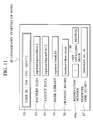
- FIG.11 is an example of the lithography starting up menu of the first embodiment of the present invention.
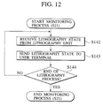
- FIG.12 is a flowchart illustrating the monitoring process shown in FIG.3B.
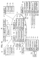
- FIG.13 is an example of the lithography state monitoring window of the first embodiment of the present invention.
- FIG.14 is a flowchart illustrating the termination process shown in FIG.3B.
- FIG.15 is a chart illustrating a relationship between the reservation time and the charging time according to the first embodiment of the present invention.
- FIG.16 is a conceptual diagram illustrating the mask manufacturing system according to the second embodiment of the present invention.
- FIG.17 is a block diagram illustrating the mask manufacturing system shown in FIG.16.
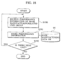
- FIG.18, FIG.19A, and FIG.19B are flowcharts illustrating the mask manufacturing method according to the second embodiment of the present invention.
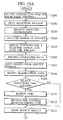
- FIG.19C is a flowchart illustrating the termination process shown in FIG.19B.
- FIG.20 is an example of the selection window of the second embodiment of the present invention.
- an LSI mask manufacturing system includes a portal site server 1, a first user terminal 3a, a second user terminal 3b, a third user terminal 3c,a first host terminal 4a having a first lithography unit 5a 1 , a second lithography unit 5a 2 , and a third lithography unit 5a 3 , a second host terminal 4b having a fourth lithography unit 5b 1 , a fifth lithography unit 5b 2 and a sixth lithography unit 5b 3 , a third host terminal 4c having a seventh lithography unit 5c 1 , an eighth lithography unit 5c 2 and a ninth lithography unit 5c 3 , a fourth host terminal 4d having a tenth lithography unit 5d 1 , an eleventh lithography unit 5d 2 and a twelfth lithography unit 5d 3 , and a network 6 connecting the portal site server 1, the user terminals 3a-3c and
- Internet is proposed as one example of network 6.
- other networks such as LAN or a personal computer communication network are alternatives and preferable.
- all of the first host terminal 4a, the second host terminal 4b, the third host terminal 4c, and the fourth host terminal 4d may be connected to network 6 in one country or in a plural countries.
- the first host terminal 4a and the second host terminal 4b are connected to network 6 in Japan
- the third host terminal 4c is connected to network 6 in the U.S.A.
- the fourth host terminal 4d may be connected to network 6 in Germany.
- the portal site server 1 accepts request of the first user terminal 3a, the second user terminal 3b, and the third user terminal 3c, and reserves one of the first lithography unit 5a1 through the twelfth lithography unit 5a12, which is connected to the first host terminal 4a through the fourth host terminal 4d and conforming the user request.
- the first user terminal 3a, the second user terminal 3b, and the third user terminal 3c are possible to communicate with the portal site server 1.
- the portal site server 1 the first user terminal 3a, the second user terminal 3b, and the third user terminal 3c search lithography units, further connected to the first host terminal 4a through the fourth host terminal 4d, and request for a reservation.
- Each of the first lithography unit 5a 1 through the twelfth lithography unit 5d 3 are connected to one of the first host terminal 4a through the fourth host terminal 4d.
- the first host terminal 4a through the fourth host terminal 4d accepts an order of the user from portal site server 1 by using the network 6.
- a completed mask is delivered to the user using a conveyance by land or air.
- Each of the portal site server 1, the first through the third user terminals 3a-3c, the first through fourth host terminal 4a-4d includes CPU, an input device, output device, main memory unit, and an secondary memory (a hard disk). Then, each of the CPU analyzes received message from the network 6 and includes an online control unit, which executes the requested processes. In addition, the CPU also includes a communication control unit to transmit received messages to this online control unit through the network 6. Furthermore, CPU 2, located on the portal site server 1, includes a database management unit. When the inputs and outputs is needed for the user ID database 30, the lithography data database 31, the lithography unit database 32, and the window database 33, the database control unit searches for the place to store files, retrieves requested files and edit the files.
- the portal site server 1 includes an input unit 35, an output unit 36, a main memory 37, an input/output control unit 38, a communication control unit 39, the user ID database 30, the lithography data database 31, the lithography unit database 32, the window database 33, and CPU 2.
- the user ID database 30, the lithography data database 31, the lithography unit database 32 and the window database 33 are stored in the portal site server 1.
- the user ID database 30, the lithography data database 31, the lithography unit database 32 and the window database 33 may be connected through the database servers.
- User ID database 30 stores an identification number given to each user. From the identification number stored in the user ID database 30, it is possible to acquire information where the data is stored.
- the lithography data database 31 is a memory storage to temporary store a lithography data of the LSI masks that the user received from the first through third user terminal 3a - 3c.
- the lithography unit 32 stores the information of each of the lithography unit 5a 1 -5d 3 connected to one of the host terminals 4a-4d, and searches for lithography unit, which meets the user needs.
- the window database 33 is a data storage device to store windows for various services providing at the portal site server 1.
- CPU 2 of portal site server 1 comprises sending unit 9, order receiving unit 10, lithography data receiving unit 11, lithography time prediction unit 12, lithography unit searching unit 13, lithography unit reservation unit 14, lithography configuration unit 15, lithography monitoring unit 16, lithography data deleting unit 17, lithography unit charging unit 18.
- the sending unit 9 selects each window stored in the window database 33 based on a request from the first user terminal 3a through the third user terminal 3c appropriately and sends selected window to one of the user terminals 3a-3c.
- the order receiving unit 10 receives a mask lithography request from the user terminals 3a-3c.
- the lithography data receiving unit 11 receives a lithography data from the user terminals 3a-3c.
- the lithography time prediction unit 12 estimates the time required for a mask lithography in the lithography unit 5x 1 .
- the user determines the reservation time of the lithography unit 5x 1 based on the duration, which the lithography time prediction unit 12 predicted.
- the lithography unit searching unit 13 searches for the most suitable lithography unit 5x 1 based on the lithography conditions received from the user terminals 3a through 3c.
- the lithography unit reservation unit 14 reserves the lithography unit 5x 1 based on the request from the first through third user terminals 3a-3c.
- the lithography configuration unit 15 configures the mask lithography conditions at the lithography unit 5x 1 .
- the user may manually configure the lithography configuration unit 15 by using the first user terminal 3a through the third user terminal 3c.
- the user is also able to select automatically the configurations the lithography conditions.
- the lithography monitoring unit 16 receives lithography state from the lithography unit 5x 1 , and send the lithography states to the first user terminal 3a through the third user terminal 3c.
- the lithography data deleting unit 17 receives the deleting data from the first user terminal 3a through the third user terminal 3c based on the request, and deletes the lithography data stored in the lithography data database 31.
- Lithography unit charging unit 18 charges to the first user terminal 3a through the third user terminal 3c based on an actual time the lithography unit 5x 1 was in use, and clear the mask lithography service provided by the LSI mask lithographing system.
- the input unit 35 may include a key board, a mouse and an optical character reader (OCR) or similar recognition device a graphics input unit such as an image scanner, or a special input unit such as a voice pattern recognition unit, while the output unit 36 may include a display unit such as a liquid crystal display, a cathode ray tube (CRT) display, or a printer such as an ink jet printer or a laser printer.
- OCR optical character reader
- a graphics input unit such as an image scanner
- a special input unit such as a voice pattern recognition unit
- the output unit 36 may include a display unit such as a liquid crystal display, a cathode ray tube (CRT) display, or a printer such as an ink jet printer or a laser printer.
- CTR optical character reader
- printer such as an ink jet printer or a laser printer.
- the input/output control unit (the input/output interface unit) 38 is an interface which connects the input unit 35, output unit 36, reading unit which reads data from storage media such as a compact disk read only memory (CD-ROM), a magnetic optical disk (MO) or a flexible disk (FD), to the CPU 2.
- the main memory 37 includes a read only memory (ROM) and a random access memory (RAM).
- the ROM functions as a program memory for storing programs to be executed in the CPU2.
- the RAM functions as a temporary data memory used as a working area for temporarily storing data used during program execution in the CPU2.
- the communication control device 24 is an interface for connecting with the network 6. Accordingly, this may be, for example, a Terminal Adapter (TA), a dial-up router, or a LAN board. In addition, this may even be data circuit- terminating equipment such as a modem, a digital service unit (DSU), a communication control unit (CCU), or a communication control processor (CCP).
- TA Terminal
- step S23 of FIG.3B As shown in FIG.14, the termination process in step S23 of FIG.3B will be explained.
- the function of the LSI mask manufacturing system and method of the first embodiment of the present invention may be programmed and saved in a computer-readable recording medium.
- the programs saved in the recording medium is transferred to a memory in a computer system and then operated by its operating unit, thus putting the method in practice.
- the recording medium may be selected from semiconductor memories, magnetic disks, optical disks, optomagnetic disks, magnetic tapes, and any of the computer-readable recording mediums.
- the LSI mask manufacturing system, method and program according to the first embodiment of the present invention provides a system, a method and a program that a user can select and control the schedules and the lithography units.
- the LSI mask manufacturing system, method and program according to the first embodiment of the present invention also provides a system, a method and a program that is able to manufacture masks without leaking confidential information, related to lithography data and process conditions for mask manufacturing, to a third person.
- the LSI mask manufacturing system, method and program according to the first embodiment of the present invention also provides a system, a method and a program that is able to reduce the personnel expenses to provide the LSI mask manufacturing system, method and program by introducing an online ordering system.
- the LSI mask manufacturing system, method and program according to the first embodiment of the present invention may also provides a system, a method and a program that is able to reduce costs for mask manufacturing since the user does not have to own units, low in the rate of operation, for a special use or for applying high technologies. The user may share these special units with other users by using the LSI mask manufacturing system, method and program according to the first embodiment of the present invention.
- the LSI mask manufacturing system, method and program according to the first embodiment of the present invention may also provides a system, a method and a program to a wide range of users from small business users to major users (large business users).
- an LSI mask manufacturing system includes a portal site server 1, a first user terminal 3a, a second user terminal 3b, a third user terminal 3c,a first host terminal 4a having a first lithography unit 5a 1 , a second lithography unit 5a 2 , a third lithography unit 5a 3 , a first computer-aided design unit (CAD) 5a 4 and a second CAD 5a 5 , a second host terminal 4b having a fourth lithography unit 5b 1 , a fifth lithography unit 5b 2 and a sixth lithography unit 5b 3 , a third host terminal 4c having a seventh lithography unit 5c 1 , an eighth lithography unit 5c 2 , a ninth lithography unit 5c 3 , a first developing unit5c 4 , a first ashing unit5c 5 , a first mask check unit 5c 6 and a first etching unit 5c 8 , a
- Internet is proposed as one example of network 6.
- other networks such as LAN or a personal computer communication network are alternatives and preferable.
- all of the first host terminal 4a, the second host terminal 4b, the third host terminal 4c, the fourth host terminal 4d, the fifth host terminal 4e and the sixth host terminal 4f may be connected to network 6 in one country or in a plural countries.
- the first host terminal 4a and the second host terminal 4b are connected to network 6 in Japan
- the third host terminal 4c is connected to network 6 in the U.S.A.
- the fourth host terminal 4d may be connected to network 6 in Germany.
- the LSI mask manufacturing system in the second embodiment of the present invention has many structures that the LSI mask manufacturing system in the first embodiment of the present invention shown in FIG.1 and FIG.2. Therefore, only the different structures of the LSI mask manufacturing system in the second embodiment of the present invention will be explained.
- the portal site server 1 in the second embodiment of the present invention is different from the portal site server 1 in the first embodiment shown in FIG.2 since the portal site server 1 in the second embodiment of the present invention has a central processing unit (CPU) 2 including a sending unit 9, a data receiving unit 21, a time prediction unit 22, a mask manufacturing machine searchingunit 23, a mask manufacturing machine reservation unit, a configuration unit 25, a monitoring unit 26, a data deletion unit 27, a charging unit 28 and an ordered range determination unit 29.
- the portal site server 1 of the second embodiment of the present invention includes a mask manufacturing data database 95 and a mask manufacturing unit database 96 as well as an ID database 30 and a window database 33.
- the portal site server 1 of the second embodiment of the present invention is connected to a mask manufacturing related unit group 5 through a network 6.
- the mask manufacturing related unit group 5 has a CAD 5x 2 which generate drawing data for masks from design data, a lithography unit 5x 1 which draws a mask based on a drawing data, a developing unit 5x 3 which develops resist patterns, an ashing unit 5x 4 an etching unit 5x 6 which etches a resist which is a film shielded by chrome or chromic oxide as an etching mask, an ashing unit 5x 4 which ashes the etched resist, a mask check unit 5x 5 which detects for errors on the mask pattern, and an adjustment unit 5x 7 which adjusts the mask pattern.
- the mask manufacturing related unit group may be a machine having one of the above functions or a plural numbers of the above functions.
- the mask manufacturing related unit group may include only the lithography unit 5x 1 , or the mask manufacturing related unit group may include the CAD 5x 2 , the lithography unit 5x 1 , the developing unit 5x 3 , the ashing unit 5x 4 , the mask check unit 5x 5 , the etching unit 5x 6 and the adjustment unit 5x 7 .
- the CAD 5x2 may be a CAD system having various functions such as correcting optic proximity effect, converting data and generating mask layouts.
- the receiving unit 20 receives a mask manufacturing request from the user terminals 3a-3c.
- the data receiving unit 21 receives data and a reservation information from the user terminals 3a-3c.
- the time prediction unit 22 estimates the time required for an ordered process, which is a mask manufacturing. For instance, the time prediction unit 22 estimates design time required at the CAD 5x 2 and lithography time at the lithography unit 5x 1 .
- the mask manufacturing machine searching unit 23 searches for the most suitable machines based on the reservation conditions received from the user terminals 3a-3c, create a list of the possible selection of the machines, and sends the list to the user terminals 3a-3c. For example, if the user select the processes up to the developing process, the mask manufacturing machine searching unit 23 searches for lithography units, CADs and developing units which satisfy the ordered conditions, create a list and sends the list to the user terminals 3a-3c.
- the mask manufacturing machine reservation unit 24 reserves at least one of the mask manufacturing units based on the request from the first through the third user terminals 3a-3c. For instance, when the user specifies the fifth CAD 5e 2 , the fourth lithography unit 5b 1 , the second developing unit 5d 4 , the second ashing unit 5d 3 and the second mask check unit 5d 6 , the mask manufacturing machine reservation unit 24 reserves the fifth CAD 5e 2 , the fourth lithography unit 5b 1 , the second developing unit 5d 4 , the second ashing unit 5d 3 and the second mask check unit 5d 6 for each processes.
- the user does not need to select machines or units from the same host terminal. The user may select machines or units from a plural number of host terminals.
- all of the first host terminal 4a through the sixth host terminal 4f may not be connected to the network 6 in a domestic level, but in an international level.
- the configuration unit 25 configures detailed conditions at each of the units specified by the user. For instance, the user may specify the first CAD 5a 4 and the first lithography unit 5a 1 , and the configuration unit 25 configures detailed conditions at each of the first CAD 5a 4 and the first lithography unit 5a 1 .
- the monitoring unit 26 receives progress reports from each of the units and sends the progress reports to the user terminals 3a-3c. For example, if the user selects the first CAD 5a 4 and the first lithography unit 5a 1 , the monitoring unit 26 receives progress reports from the first CAD 5a 4 and sends the progress reports to the user terminals 3a-3c first. When the design process is finished at the first CAD 5a 4 , the monitoring unit 26 receives progress reports from the first lithography unit 5a 1 and sends the progress reports to the user terminals 3a-3c.
- the data deleting unit 27 receives the deleting data from the user terminals 3a-3c based on the request, and deletes the data sent and stored at each of the specified machines and units.
- the charging unit 28 charges to the user terminals 3a-3c based on an actual time the machines and units are used. Then, the collected charges are paid to owners of the each machines and units.
- the ordered range determination unit 29 determines the ordered range based on received reservation information from the user terminals 3a-3c.
- the mask manufacturing data database 95 is connected to the portal site server 1 and stores data needed for mask manufacturing.
- the "data needed for mask manufacturing” may be data needed for each ordered processes. Therefore, if the ordered process starts from the design process, design specification data is one of the "data needed for mask manufacturing.”
- the mask manufacturing unit database 96 is connected to the portal site server 1 and stores performance information of the first through the third lithography units 5a 1 -5a 3 , the fourth through the sixth lithography unit 5b 1 -5b 3 , the seventh through the ninth lithography unit 5c 1 -5c 3 , the tenth through the twelfth lithography unit 5d 1 -5d 3 , the first CAD 5a 4 , the second CAD 5a 5 , the third CAD 5d 7 , the fourth CAD 5e 1 through the sixth CAD 5e 3 , the seventh CAD 5f 1 through the ninth CAD 5f 3 , the first developing unit 5c 4 , the second developing unit 5d 4 , the first ashing unit 5
- FIG.18 As shown in FIG.18, FIG.19A and FIG.19B, an LSI mask manufacturing method of the second embodiment of the present invention will be explained.
- the function of the LSI mask manufacturing system and method of the second embodiment of the present invention may be programmed and saved in a computer-readable recording medium.
- the programs saved in the recording medium is transferred to a memory in a computer system and then operated by its operating unit, thus putting the method in practice.
- the recording medium may be selected from semiconductor memories, magnetic disks, optical disks, optomagnetic disks, magnetic tapes, and any of the computer-readable recording mediums.
- the LSI mask manufacturing system, method and program according to the second embodiment of the present invention provides a system, a method and a program that a user can select and control the schedules and the lithography units.
- the LSI mask manufacturing system, method and program according to the second embodiment of the present invention also provides a system, a method and a program that is able to manufacture masks without leaking confidential information, related to lithography data and process conditions for LSI mask manufacturing, to a third person.
- the LSI mask manufacturing system, method and program according to the second embodiment of the present invention also provides a system, a method and a program that is able to reduce the personnel expenses to provide an LSI mask manufacturing system by introducing an online ordering system.
- the LSI mask manufacturing system, method and program according to the second embodiment of the present invention may also provide a system, a method and a program that is able to reduce costs for LSI mask manufacturing since the user does not have to own units and machines, although low in the rate of operation, but needed for a special use or for applying high technologies. The user may share these special units with other users by using the LSI mask manufacturing system, method and program according to the first embodiment of the present invention.
- the LSI mask manufacturing system, method and program according to the second embodiment of the present invention may also provide a system, a method and a program to a wide range of users from small business users to major users (large business users).
- the first lithography unit 5a 1 through the third lithography unit 5a 3 , the first CAD 5a 4 , the second CAD 5a 5 , the fourth lithography unit 5b 1 - the sixth lithography unit 5b 3 , the seventh lithography unit 5c 1 - the ninth lithography unit 5c 3 , the first developing unit 5c 4 , the first ashing unit 5c 5 , the first mask check unit 5c 6 , the first etching unit 5c 8 , the tenth lithography unit 5d 1 - the twelfth lithography unit 5d 3 , the second developing unit 5d 4 , the second ashing unit 5d 5 , the second mask check unit 5d 6 , the third CAD 5d 7 , the second etching unit 5d 8 , the adjustment unit 5d 9 , the fourth CAD 5e 1 - the sixth CAD 5e 3 and the seventh CAD 5f 1 - the ninth CAD 5f 3 may be connected to the first through the sixth host terminal
- the first host terminal 4a through the sixth host terminal 4f may be connected to the network 6 in domestic level or in the international level. In other words, some of the host terminals may be connected to the network 6 in different countries.
Landscapes
- Engineering & Computer Science (AREA)
- Physics & Mathematics (AREA)
- General Physics & Mathematics (AREA)
- Theoretical Computer Science (AREA)
- Evolutionary Computation (AREA)
- General Engineering & Computer Science (AREA)
- Geometry (AREA)
- Computer Hardware Design (AREA)
- Exposure And Positioning Against Photoresist Photosensitive Materials (AREA)
- Mobile Radio Communication Systems (AREA)
- Management, Administration, Business Operations System, And Electronic Commerce (AREA)
- Preparing Plates And Mask In Photomechanical Process (AREA)
- Exposure Of Semiconductors, Excluding Electron Or Ion Beam Exposure (AREA)
- General Factory Administration (AREA)
Abstract
Description
Claims (22)
- An LSI mask manufacturing system, comprising:a network;a portal site server configured to be connected to the network;a user terminal configured to be connected to the portal site server;a host terminal configured to be connected to the network; andlithography units configured to be connected to the host terminal.
- The system of claim 1, wherein the portal site server comprises:a lithography data receiving unit configured to receive lithography data and a lithography reservation condition for a lithography process from the user terminal;a lithography data database configured to store the lithography data;a lithography unit database configured to store a performance information of the lithography unit;a lithography unit searching unit configured to search for a lithography unit matching to the lithography reservation condition, generate a list of lithography units, and send the list to the user terminal; anda lithography unit reservation unit configured to receive information of a lithography unit specified by the user terminal and send a lithography request to the lithography unit specified by the user terminal.
- The system of claim 2 further comprising a lithography charging unit configured to calculate a charging amount based on an actual used time at the lithography unit and send a bill to the user terminal.
- The system of claim 2 further comprising a lithography data deleting unit configured to delete the lithography data from the lithography data database.
- The system of claim 2 further comprising:a lithography time prediction unit configured to estimate a lithography time based on the lithography reservation condition;a lithography configuration unit configured to setup detail of a lithography condition for LSI mask manufacturing at the lithography unit; anda lithography monitoring unit configured to receive a lithography state from the lithography unit and send the lithography state to the user terminal.
- An LSI mask manufacturing system, comprising:a network;a portal site server configured to be connected to the network;a user terminal configured to be connected to the portal site server;a host terminal configured to be connected to the network; anda mask manufacturing unit configured to be connected to the host terminal.
- The system of claim 5, wherein the portal site server comprises:a data receiving unit configured to receive data and a reservation condition for LSI mask manufacturing from the user terminal;a mask manufacturing data database configured to store the data and the reservation condition;a mask manufacturing unit database configured to store performance information of the mask manufacturing unit;an ordered range determination unit configured to determine an ordered range based on the reservation condition;a mask manufacturing machine searching unit configured to search for a mask manufacturing unit matches to the reservation condition, generate a list of mask manufacturing units, and send the list to the user terminal; anda mask manufacturing machine reservation unit configured to receive information of information of a mask manufacturing unit specified by the user terminal and send a request to the mask manufacturing unit specified by the user terminal.
- The system of claim 7 further comprising a charging unit configured to calculate a charging amount based on an actual used time at the mask manufacturing unit and send a bill to the user terminal.
- The system of claim 7 further comprising a data deleting unit configured to delete the data from the mask manufacturing unit.
- The system of claim 7 further comprising:a time prediction unit configured to estimate a mask manufacturing time at the mask manufacturing unit specified by the user terminal based on the reservation condition;a configuration unit configured to setup detail of a condition for mask manufacturing at the mask manufacturing unit specified by the user terminal; andamonitoring unit configured to receive a mask manufacturing state from the mask manufacturing unit specified by the user terminal and send the mask manufacturing state to the user terminal.
- The system of claim 6, wherein the mask manufacturing unit comprises:a CAD unit configured to design a mask pattern based on a design data and generate a lithography data for a mask;a lithography unit configured to expose the mask pattern on to a resist film of the mask;a developing unit configured to develop the resist film exposed at the lithography unit;an etching unit configured to etch a shielded layer of the mask based on the resist film developed by the developing unit;an ashing unit configured to remove the resist film from the mask;a mask check unit configured to check for an error of the mask pattern; andan adjusting unit configured to adjust the error of the mask pattern.
- The system of claim 7, wherein the ordered range comprises at least one of the design unit, the lithography unit, the developing unit, the etching unit, the ashing unit, the mask check unit and the adjusting unit.
- A computer implemented method for LSI mask manufacturing comprising:storing performance information of a lithography unit, connected to a network, in a lithography unit database;receiving a lithography data and a lithography reservation condition from a user terminal connected to the network;storing the lithography data in a lithography data database;searching for a lithography unit matching to the lithography reservation condition, generating a list of lithography units, and sending the list to the user terminal; andreceiving information of a lithography unit specified by the user terminal and sending a lithography request to the lithography unit specified by the user terminal.
- The method of claim 13 further comprising:calculating a charging amount based on an actual used time of the lithography unit; andsending a bill to the user terminal.
- The method of claim 13 further comprising deleting the lithography data from the lithography data database.
- The method of claim 13 further comprising:estimating a lithography time based on the lithography reservation condition;setting up detail of a lithography condition for LSI mask manufacturing at the lithography unit; andreceiving a lithography state from the lithography unit and sending the lithography state to the user terminal.
- A computer implemented method for LSI mask manufacturing, the method comprising:storing performance information of a mask manufacturing unit, connected to a network, in a mask manufacturing unit database;receiving data and a reservation condition from a user terminal connected to the network;storing the data in a mask manufacturing data database;determining a ordered range based on the reservation condition;searching for a mask manufacturing unit marching to the reservation condition, generating a list of mask manufacturing units, and sending the list to the user terminal; andreceiving information of a mask manufacturing unit specified by the user terminal and sending a request to the mask manufacturing unit specified by the user terminal.
- The method of claim 17, further comprising:calculating a charging amount based on an actual used time of the mask manufacturing unit;sending a bill to the user terminal; anddeleting the data from the mask manufacturing unit specified by the user terminal.
- The method of claim 17, further comprising:estimating a mask manufacturing time based on the reservation condition;setting up detail of a mask manufacturing condition at the mask manufacturing unit; andreceiving a mask manufacturing state from the mask manufacturing unit and sending the mask manufacturing state to the user terminal.
- The method of claim 17, wherein the mask manufacturing unit comprises:a CAD unit configured to design a mask pattern based on a design data and generate a lithography data for a mask;a lithography unit configured to expose the mask pattern on to a resist film of the mask;a developing unit configured to develop the resist film exposed at the lithography unit;an etching unit configured to etch a shielded layer of the mask based on the resist film developed by the developing unit;an ashing unit configured to remove the resist film from the mask;a mask check unit configured to check for an error of the mask pattern; andan adjusting unit configured to adjust the error of the mask pattern.
- A computer program product for use with a mask manufacturing unit, the computer program product comprising:instructions to store performance information of a lithography unit, connected to a network, in a lithography unit database;instructions to receive a lithography data and a lithography reservation condition from a user terminal connected to the network;instructions to store the lithography data in a lithography data database;instructions to search for a lithography unit matching to the lithography reservation condition, generate a list of lithography units, and send the list to the user terminal; andinstructions to receive information of a lithography unit specified by the user terminal and send a lithography request to the lithography unit specified by the user terminal.
- A computer program product for use with a mask manufacturing unit the computer program product comprising:instructions to store performance information of a mask manufacturing unit, connected to a network, in a mask manufacturing unit database;instructions to receive data and a reservation condition from a user terminal connected to the network;instructions to store the data in a mask manufacturing data database;instructions to determine an ordered range based on the reservation condition;instructions to search for a mask manufacturing unit matching to the reservation condition, generate a list of mask manufacturing units, and send the list to the user terminal; andinstructions to receive information of amaskmanufacturing unit specified by the user terminal and send a request to the mask manufacturing unit specified by the user terminal.
Applications Claiming Priority (2)
| Application Number | Priority Date | Filing Date | Title |
|---|---|---|---|
| JP2002090029A JP2003288496A (en) | 2002-03-27 | 2002-03-27 | Drawing support system, drawing support method, mask manufacturing support system, and mask manufacturing support method |
| JP2002090029 | 2002-03-27 |
Publications (3)
| Publication Number | Publication Date |
|---|---|
| EP1349091A2 true EP1349091A2 (en) | 2003-10-01 |
| EP1349091A3 EP1349091A3 (en) | 2003-12-17 |
| EP1349091B1 EP1349091B1 (en) | 2006-08-02 |
Family
ID=27800498
Family Applications (1)
| Application Number | Title | Priority Date | Filing Date |
|---|---|---|---|
| EP03006732A Expired - Lifetime EP1349091B1 (en) | 2002-03-27 | 2003-03-25 | LSI mask manufacturing system, LSI mask manufacturing method and LSI mask manufacturing program |
Country Status (6)
| Country | Link |
|---|---|
| US (1) | US7047094B2 (en) |
| EP (1) | EP1349091B1 (en) |
| JP (1) | JP2003288496A (en) |
| CN (1) | CN1447384A (en) |
| DE (1) | DE60307154T2 (en) |
| TW (1) | TWI221570B (en) |
Families Citing this family (6)
| Publication number | Priority date | Publication date | Assignee | Title |
|---|---|---|---|---|
| AU2001238036A1 (en) * | 2000-02-16 | 2001-08-27 | Cymer, Inc. | Process monitoring system for lithography lasers |
| US7260442B2 (en) * | 2004-03-03 | 2007-08-21 | Taiwan Semiconductor Manufacturing Co., Ltd. | Method and system for mask fabrication process control |
| US20060129821A1 (en) * | 2004-12-13 | 2006-06-15 | Microsoft Corporation | Believably trustworthy enforcement of privacy enhancing technologies in data processing |
| KR102072200B1 (en) * | 2011-04-22 | 2020-01-31 | 에이에스엠엘 네델란즈 비.브이. | Network architecture and protocol for cluster of lithography machines |
| JP6128744B2 (en) * | 2012-04-04 | 2017-05-17 | キヤノン株式会社 | Drawing apparatus, drawing method, and article manufacturing method |
| JP6396200B2 (en) * | 2014-12-19 | 2018-09-26 | 株式会社ニューフレアテクノロジー | Charged particle beam drawing apparatus and charged particle beam drawing method |
Family Cites Families (12)
| Publication number | Priority date | Publication date | Assignee | Title |
|---|---|---|---|---|
| JPS5821422B2 (en) * | 1980-12-26 | 1983-04-30 | 株式会社東芝 | Charged beam exposure equipment |
| JPS57180128A (en) * | 1981-04-30 | 1982-11-06 | Toshiba Corp | Equipment for electron beam exposure |
| US5495417A (en) * | 1990-08-14 | 1996-02-27 | Kabushiki Kaisha Toshiba | System for automatically producing different semiconductor products in different quantities through a plurality of processes along a production line |
| JP3336436B2 (en) * | 1991-04-02 | 2002-10-21 | 株式会社ニコン | Lithography system, information collecting apparatus, exposure apparatus, and semiconductor device manufacturing method |
| CA2194106A1 (en) * | 1995-12-29 | 1997-06-30 | Foy C. Sperring | Remote printing system |
| JP3431387B2 (en) * | 1996-03-14 | 2003-07-28 | 株式会社東芝 | Exposure intensity distribution display method and mask pattern editing device |
| US6051347A (en) * | 1999-03-18 | 2000-04-18 | Taiwan Semiconductor Manufacturing Company | Application of e-beam proximity over-correction to compensate optical proximity effect in optical lithography process |
| US6347258B1 (en) * | 1999-09-23 | 2002-02-12 | Taiwan Semiconductor Manufacturing Co., Ltd. | Data structure of a product technology and a method of preparing the same |
| US6952656B1 (en) * | 2000-04-28 | 2005-10-04 | Applied Materials, Inc. | Wafer fabrication data acquisition and management systems |
| JP2002075820A (en) | 2000-08-24 | 2002-03-15 | Hitachi Ltd | License system and method for licensing semiconductor manufacturing equipment |
| JP2002092062A (en) | 2000-09-13 | 2002-03-29 | Yamaha Corp | Device for designing integrated circuit and method for the same and storage medium with its program stored therein |
| JP2002149754A (en) | 2000-11-07 | 2002-05-24 | Toshiba Microelectronics Corp | Work management system and work management method |
-
2002
- 2002-03-27 JP JP2002090029A patent/JP2003288496A/en active Pending
-
2003
- 2003-03-21 TW TW092106366A patent/TWI221570B/en not_active IP Right Cessation
- 2003-03-25 DE DE60307154T patent/DE60307154T2/en not_active Expired - Lifetime
- 2003-03-25 EP EP03006732A patent/EP1349091B1/en not_active Expired - Lifetime
- 2003-03-26 US US10/397,543 patent/US7047094B2/en not_active Expired - Fee Related
- 2003-03-27 CN CN03121241A patent/CN1447384A/en active Pending
Also Published As
| Publication number | Publication date |
|---|---|
| JP2003288496A (en) | 2003-10-10 |
| US20030188289A1 (en) | 2003-10-02 |
| EP1349091A3 (en) | 2003-12-17 |
| DE60307154T2 (en) | 2007-10-25 |
| US7047094B2 (en) | 2006-05-16 |
| TWI221570B (en) | 2004-10-01 |
| EP1349091B1 (en) | 2006-08-02 |
| TW200305093A (en) | 2003-10-16 |
| CN1447384A (en) | 2003-10-08 |
| DE60307154D1 (en) | 2006-09-14 |
Similar Documents
| Publication | Publication Date | Title |
|---|---|---|
| US7318214B1 (en) | System and method for reducing patterning variability in integrated circuit manufacturing through mask layout corrections | |
| TWI364679B (en) | Model-based sraf insertion | |
| KR101151958B1 (en) | Comprehensive front end method and system for automatically generating and processing photomask orders | |
| CN101470344B (en) | Method for performing pattern decomposition for a full chip design | |
| US6968530B2 (en) | Network-based photomask data entry interface and instruction generator for manufacturing photomasks | |
| JP4104574B2 (en) | Improved method and apparatus for sub-micron IC design using edge fragment tagging to correct edge placement distortion | |
| US6868355B2 (en) | Automatic calibration of a masking process simulator | |
| US6842881B2 (en) | Rule based system and method for automatically generating photomask orders in a specified order format | |
| CN101520810A (en) | System and method for multi-exposure pattern decomposition | |
| EP1594008A2 (en) | Method and apparatus for submicron ic design using edge fragment tagging | |
| US7640529B2 (en) | User-friendly rule-based system and method for automatically generating photomask orders | |
| EP1349091B1 (en) | LSI mask manufacturing system, LSI mask manufacturing method and LSI mask manufacturing program | |
| JP2004279950A (en) | Photomask, method of manufacturing the same, semiconductor integrated circuit and method of manufacturing the same | |
| US20060122724A1 (en) | System and method for automatically generating a tooling specification using a logical operations utility that can be used to generate a photomask order | |
| US20030187750A1 (en) | Photomask supply system with photomask production period shortened | |
| US20040039584A1 (en) | Method of selecting mask manufacturer of photomask | |
| US20050055659A1 (en) | Rule based system and method for automatically generating photomask orders by conditioning information from a customer's computer system | |
| US20060271443A1 (en) | System and method for automatically generating and/or processing a photomask order using a script profiler | |
| JP2003188089A (en) | Exposure condition calculation method, exposure condition calculation program, recording medium, reticle manufacturing method, structure manufacturing method, apparatus, and exposure condition calculation service providing method | |
| KR20100138780A (en) | Particle generation factor determination system, charging method and storage medium | |
| JP3603027B6 (en) | Improved method and apparatus for sub-micron IC design using edge fragment tagging to correct edge placement distortion | |
| EA009013B1 (en) | COMPLEX INTERFACE METHOD AND SYSTEM FOR AUTOMATIC CREATION AND PROCESSING ORDERS FOR PHOTOMASK | |
| CN101023397A (en) | Rule based system and method for automatically generating photomask orders | |
| KR20070030920A (en) | Rule-based System and Method for Automatic Generation of Photomask Orders | |
| EA008878B1 (en) | BASED ON THE RULE SYSTEM AND METHOD OF AUTOMATIC GENERATION OF ORDERS FOR PHOTOMASK |
Legal Events
| Date | Code | Title | Description |
|---|---|---|---|
| PUAI | Public reference made under article 153(3) epc to a published international application that has entered the european phase |
Free format text: ORIGINAL CODE: 0009012 |
|
| 17P | Request for examination filed |
Effective date: 20030325 |
|
| AK | Designated contracting states |
Kind code of ref document: A2 Designated state(s): AT BE BG CH CY CZ DE DK EE ES FI FR GB GR HU IE IT LI LU MC NL PT RO SE SI SK TR |
|
| AX | Request for extension of the european patent |
Extension state: AL LT LV MK |
|
| PUAL | Search report despatched |
Free format text: ORIGINAL CODE: 0009013 |
|
| AK | Designated contracting states |
Kind code of ref document: A3 Designated state(s): AT BE BG CH CY CZ DE DK EE ES FI FR GB GR HU IE IT LI LU MC NL PT RO SE SI SK TR |
|
| AX | Request for extension of the european patent |
Extension state: AL LT LV MK |
|
| 17Q | First examination report despatched |
Effective date: 20040226 |
|
| AKX | Designation fees paid |
Designated state(s): DE FR GB |
|
| GRAP | Despatch of communication of intention to grant a patent |
Free format text: ORIGINAL CODE: EPIDOSNIGR1 |
|
| GRAS | Grant fee paid |
Free format text: ORIGINAL CODE: EPIDOSNIGR3 |
|
| GRAA | (expected) grant |
Free format text: ORIGINAL CODE: 0009210 |
|
| AK | Designated contracting states |
Kind code of ref document: B1 Designated state(s): DE FR GB |
|
| REG | Reference to a national code |
Ref country code: GB Ref legal event code: FG4D |
|
| REF | Corresponds to: |
Ref document number: 60307154 Country of ref document: DE Date of ref document: 20060914 Kind code of ref document: P |
|
| EN | Fr: translation not filed | ||
| PLBE | No opposition filed within time limit |
Free format text: ORIGINAL CODE: 0009261 |
|
| STAA | Information on the status of an ep patent application or granted ep patent |
Free format text: STATUS: NO OPPOSITION FILED WITHIN TIME LIMIT |
|
| 26N | No opposition filed |
Effective date: 20070503 |
|
| PG25 | Lapsed in a contracting state [announced via postgrant information from national office to epo] |
Ref country code: FR Free format text: LAPSE BECAUSE OF FAILURE TO SUBMIT A TRANSLATION OF THE DESCRIPTION OR TO PAY THE FEE WITHIN THE PRESCRIBED TIME-LIMIT Effective date: 20070511 |
|
| PG25 | Lapsed in a contracting state [announced via postgrant information from national office to epo] |
Ref country code: FR Free format text: LAPSE BECAUSE OF FAILURE TO SUBMIT A TRANSLATION OF THE DESCRIPTION OR TO PAY THE FEE WITHIN THE PRESCRIBED TIME-LIMIT Effective date: 20060802 |
|
| PGFP | Annual fee paid to national office [announced via postgrant information from national office to epo] |
Ref country code: GB Payment date: 20120321 Year of fee payment: 10 |
|
| PGFP | Annual fee paid to national office [announced via postgrant information from national office to epo] |
Ref country code: DE Payment date: 20120411 Year of fee payment: 10 |
|
| GBPC | Gb: european patent ceased through non-payment of renewal fee |
Effective date: 20130325 |
|
| REG | Reference to a national code |
Ref country code: DE Ref legal event code: R119 Ref document number: 60307154 Country of ref document: DE Effective date: 20131001 |
|
| PG25 | Lapsed in a contracting state [announced via postgrant information from national office to epo] |
Ref country code: GB Free format text: LAPSE BECAUSE OF NON-PAYMENT OF DUE FEES Effective date: 20130325 Ref country code: DE Free format text: LAPSE BECAUSE OF NON-PAYMENT OF DUE FEES Effective date: 20131001 |