EP1348652A2 - Powdery particle conveying system and roots blower operating method - Google Patents
Powdery particle conveying system and roots blower operating method Download PDFInfo
- Publication number
- EP1348652A2 EP1348652A2 EP03006542A EP03006542A EP1348652A2 EP 1348652 A2 EP1348652 A2 EP 1348652A2 EP 03006542 A EP03006542 A EP 03006542A EP 03006542 A EP03006542 A EP 03006542A EP 1348652 A2 EP1348652 A2 EP 1348652A2
- Authority
- EP
- European Patent Office
- Prior art keywords
- conveying
- roots blower
- powdery
- motor
- reservoir tank
- Prior art date
- Legal status (The legal status is an assumption and is not a legal conclusion. Google has not performed a legal analysis and makes no representation as to the accuracy of the status listed.)
- Granted
Links
Images


Classifications
-
- B—PERFORMING OPERATIONS; TRANSPORTING
- B65—CONVEYING; PACKING; STORING; HANDLING THIN OR FILAMENTARY MATERIAL
- B65G—TRANSPORT OR STORAGE DEVICES, e.g. CONVEYORS FOR LOADING OR TIPPING, SHOP CONVEYOR SYSTEMS OR PNEUMATIC TUBE CONVEYORS
- B65G53/00—Conveying materials in bulk through troughs, pipes or tubes by floating the materials or by flow of gas, liquid or foam
- B65G53/34—Details
- B65G53/66—Use of indicator or control devices, e.g. for controlling gas pressure, for controlling proportions of material and gas, for indicating or preventing jamming of material
-
- B—PERFORMING OPERATIONS; TRANSPORTING
- B65—CONVEYING; PACKING; STORING; HANDLING THIN OR FILAMENTARY MATERIAL
- B65G—TRANSPORT OR STORAGE DEVICES, e.g. CONVEYORS FOR LOADING OR TIPPING, SHOP CONVEYOR SYSTEMS OR PNEUMATIC TUBE CONVEYORS
- B65G65/00—Loading or unloading
- B65G65/30—Methods or devices for filling or emptying bunkers, hoppers, tanks, or like containers, of interest apart from their use in particular chemical or physical processes or their application in particular machines, e.g. not covered by a single other subclass
-
- B—PERFORMING OPERATIONS; TRANSPORTING
- B09—DISPOSAL OF SOLID WASTE; RECLAMATION OF CONTAMINATED SOIL
- B09C—RECLAMATION OF CONTAMINATED SOIL
- B09C1/00—Reclamation of contaminated soil
- B09C1/002—Reclamation of contaminated soil involving in-situ ground water treatment
-
- B—PERFORMING OPERATIONS; TRANSPORTING
- B09—DISPOSAL OF SOLID WASTE; RECLAMATION OF CONTAMINATED SOIL
- B09C—RECLAMATION OF CONTAMINATED SOIL
- B09C1/00—Reclamation of contaminated soil
- B09C1/10—Reclamation of contaminated soil microbiologically, biologically or by using enzymes
-
- C—CHEMISTRY; METALLURGY
- C12—BIOCHEMISTRY; BEER; SPIRITS; WINE; VINEGAR; MICROBIOLOGY; ENZYMOLOGY; MUTATION OR GENETIC ENGINEERING
- C12N—MICROORGANISMS OR ENZYMES; COMPOSITIONS THEREOF; PROPAGATING, PRESERVING, OR MAINTAINING MICROORGANISMS; MUTATION OR GENETIC ENGINEERING; CULTURE MEDIA
- C12N1/00—Microorganisms, e.g. protozoa; Compositions thereof; Processes of propagating, maintaining or preserving microorganisms or compositions thereof; Processes of preparing or isolating a composition containing a microorganism; Culture media therefor
- C12N1/14—Fungi; Culture media therefor
- C12N1/145—Fungal isolates
-
- C—CHEMISTRY; METALLURGY
- C12—BIOCHEMISTRY; BEER; SPIRITS; WINE; VINEGAR; MICROBIOLOGY; ENZYMOLOGY; MUTATION OR GENETIC ENGINEERING
- C12P—FERMENTATION OR ENZYME-USING PROCESSES TO SYNTHESISE A DESIRED CHEMICAL COMPOUND OR COMPOSITION OR TO SEPARATE OPTICAL ISOMERS FROM A RACEMIC MIXTURE
- C12P39/00—Processes involving microorganisms of different genera in the same process, simultaneously
-
- C—CHEMISTRY; METALLURGY
- C12—BIOCHEMISTRY; BEER; SPIRITS; WINE; VINEGAR; MICROBIOLOGY; ENZYMOLOGY; MUTATION OR GENETIC ENGINEERING
- C12R—INDEXING SCHEME ASSOCIATED WITH SUBCLASSES C12C - C12Q, RELATING TO MICROORGANISMS
- C12R2001/00—Microorganisms ; Processes using microorganisms
- C12R2001/645—Fungi ; Processes using fungi
Definitions
- the roots blower 44 is required to have such a great capacity as to convey the flour to any of the reservoir tanks 30. Therefore, the roots blower 44 is designed to have such a capacity or volume as to convey the flour to a reservoir tank 30B located at a remotest or highest position among the reservoir tanks 30, that is, a reservoir tank of a largest conveying load.
- the roots blower having such a capacity as to sufficiently convey the powdery particles even to the reservoir tank 30B located at the remotest position is operated with its rated output, and thus, the powdery particles are conveyed to all of the reservoir tanks. That is to say, the powdery particle conveying system is operated with the roots blower driving motor at the same frequency of a power source even in the case where the flour is conveyed to a reservoir tank 30A located at a position nearest the roots blower 44 as a frequency of the power source at which the flour is conveyed to the reservoir tank 30B, and therefore, energy is wastefully used. In this case, the output of the roots blower 44 is excessive, and therefore, force greater than required is applied to the powdery particles being conveyed, thereby inducing a fear of denaturalization of the powdery particles.
- a similar problem is arisen by not only the difference in conveying distance but also the conveying quantity or kind of powdery particles to be conveyed (for example, flour, wheat bran, flour grains and the like) or the magnitude of a conveying load such as a pressure loss on a conveying channel (for example, the bend of the conveying channel, the number of switch valves, the property of the inner surface of the conveying pipe, i.e., a surface roughness, and the like).
- a conveying load such as a pressure loss on a conveying channel
- a conveying channel for example, the bend of the conveying channel, the number of switch valves, the property of the inner surface of the conveying pipe, i.e., a surface roughness, and the like.
- An object of the present invention is to provide a powdery particle conveying system which can convey powdery particles without any waste of energy according to a conveying load during the conveyance of the powdery particles and a roots blower operating method for use in the conveying system.
- an output of a roots blower is changed according to a conveying load during the conveyance of powdery particles, so that the roots blower is operated with a minimum output all times.
- the frequency of the power source voltage of a roots blower driving motor is minimized as much as possible to change the output of the roots blower thereby suppressing the rotating output of the motor. Consequently, the powdery particles can be sufficiently conveyed by operating the system with the same rated output as that in the prior art in the case of the large conveying load.
- the rotating output of the motor is reduced so as to convey the powdery particles while reducing an electric power consumption in the case of the small conveying load, thus reducing energy consumption.
- Other methods for changing the output of the roots blower include a method in which a conveying state is observed while reducing the speed of the roots blower driving motor according to the conveying load, so as to change the speed to a lowest speed at which the conveyance can be maintained; and a method in which the output of the roots blower required for each of the conveying loads is previously calculated, and then, it is stored in a memory device or the like, so that the output of the roots blower with respect to a conveying load according to powdery particles to be conveyed or conveying conditions is read out of the memory device or the like when the powdery particles to be conveyed or the conveying conditions are input, and thus, the output of the roots blower is automatically changed.
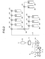
- Fig. 2 illustrates the general configuration of a powdery particle conveying system in an embodiment according to the present invention.
- powdery particles to be supplied from a hopper 12 serving as a reservoir are conveyed to a plurality of reservoir tanks 30 (A1 to A4, B1 and B2 and C1 to C3) installed at remote positions via a conveying pipe 6 on a compressed air current generated by a roots blower 2, and then, are reserved in the reservoir tanks 30.
- the hopper 12 disposed on the supplying side is connected to the conveying pipe 6 via a measuring unit 11 and a rotary valve 14 which is used for controlling the supply and sealing the air.
- the roots blower 2 is driven by a motor 4 to compress the air sucked through a suction pipe, and then, feeds out the compressed air current to the conveying pipe 6 connected onto a discharge side.
- the rotary valve 14 has the function of conveying the powdery particles, which have been fed into the conveying pipe 6, through the conveying pipe 6 without the powdery particles being injected onto the side of the hopper 12.
- a pressure gauge 3 for measuring a pressure inside of the conveying pipe 6, that is, a discharge pressure of the roots blower 2 is connected to a joint point between the discharge side of the roots blower 2 and the rotary valve 14.
- the conveying pipe 6 is branched to each of the reservoir tanks 30.
- a switch valve 10 for switching a channel for the powdery particles is provided at each branch point.
- a variable-speed motor such as an induction motor or a synchronous motor is used as the motor 4 in the roots blower 2, which has an output enough to press-feed the powdery particles to the reservoir tank located at a remotest position, that is, the reservoir tank 30 (i.e., B2) of a largest conveying load.
- Electric power is supplied to the motor 4 via an inverter (i.e., an electric power frequency converter) 7 for converting the frequency of voltage of an electric power source.
- the inverter 7 can arbitrarily convert the frequency of the voltage of the electric power source to be applied to the motor 4.
- the motor 4 may be a motor with a continuously variable transmission such as a ring cone motor. In this case, a speed controller in place of the inverter 7 is required.
- Reference numeral 1 designates a controller for controlling the output of the roots blower 2, that is, the speed of the motor 4.
- the pressure gauge 3 As illustrated in Fig. 3, to the controller 1 are connected the pressure gauge 3, a judging device 5, and an input device 8 for designating or changing the reservoir tank 30, to which the powder particles are conveyed.
- the judging device 5 judges based on a pressure value inside of the conveying pipe 6 at an outlet of the roots blower 2, sent from the pressure gauge 3 as to whether or not the powdery particle conveying system maintains the state in which there is no danger of closure of the conveying pipe.
- Judgement criteria include whether or not the pressure inside of the conveying pipe 6 tends to be reduced in a predetermined manner according to the speed reduction of the roots blower, that is, whether or not the pressure inside of the conveying pipe 6 reaches a lowest value, or whether or not a fluctuation prognosticative of the closure inside of the conveying pipe occurs in the pressure inside of the conveying pipe 6, that is, whether or not the inside of the conveying pipe 6 is temporarily or partly closed by the powdery particles.
- the controller 1 controls the speed of the motor 4 in the roots blower 2 in such a manner as to become a lowest speed within the range in which the state of no danger of the closure inside of the conveying pipe is maintained. Furthermore, based on the value sent from the judging device 5, the controller 1 changes the speed of the motor 4 to a most proper value all times.
- the functions performed by the controller 1 and the judging device 5 can be achieved by a programmable logic controller unit.
- the input device 8 inputs an identification reference B2 of the reservoir tank 30 (i.e., B2), to which the powdery particles are conveyed.
- the controller 1 outputs a command of a high frequency fh corresponding to the identification reference B2.
- the respective switch valves 10 of the reservoir tanks 30 (A1 to A4, B1 and C1 to C3) are switched by a mechanism not illustrated, thereby defining only a channel to the reservoir tank 30 (i.e., B2).
- the inverter 7 receives the frequency command from the controller 1, and then, converts the frequency of the power source voltage into a frequency fh so as to supply the frequency fh to the motor 4. Consequently, the motor 4 is rotated at the speed corresponding to the frequency fh, so that a compressed air current generated by the roots blower 2 is fed to the conveying pipe 6.
- the powdery particles contained in the hopper 12 are conveyed into the conveying pipe 6 via the rotary valve 14 together with the compressed air current, and further, are conveyed up to the reservoir tank 30 (i.e., B2) on the compressed air current.
- the frequency of the power source to the motor 4 is maintained, and therefore, the motor 4 is initially rotated at a high speed.
- the controller 1 After the start of the conveyance, the controller 1 sends a command to gradually reduce the voltage frequency of the power source to the inverter 7, and therefore, to reduce the speed of the motor 4.
- the judging device 5 judges the conveying state of the powdery particles based on the output from the pressure gauge 3. In other words, the judging device 5 monitors whether or not a ratio of a reduction width of the pressure inside of the conveying pipe 6 to a reduction width of frequency of the power source is smaller than a predetermined value, or whether or not a fluctuation prognosticative of the closure inside of the conveying pipe occurs in the pressure inside of the conveying pipe 6.
- the judging device 5 judges that the speed of the motor 4 is improper, that is, an intended conveying state cannot be maintained.
- the controller 1 sends a command to the inverter 7 to return the conveying state to a proper state, thereby increasing the frequency of the power source voltage so as to increase the speed of the motor 4.
- the conveyance is continued at the frequency at which the intended conveying state can be stably maintained.
- the power consumption by the roots blower 2 can be saved by reducing the speed of the motor 4 in the roots blower 2 to such an extent that the conveying state can be stably maintained.
- the input device 8 inputs an identification reference A1 of the reservoir tank 30 (i.e., A1). Since a conveying load is small due to a short distance from the roots blower 2 to the reservoir tank 30 (i.e., A1), the intended conveying state can be maintained at a speed of the motor 4 lower than that in the case of the conveyance to the reservoir tank 30 (i.e., B2).
- the voltage frequency of the power source can be reduced down to 45 Hz, thereby suppressing the power consumption.
- This also reduces the output of the roots blower 2, i.e., the generated air quantity, and therefore, no excessive dynamic pressure can be applied to the powdery particles, thus reducing the possibility of occurrence of denaturalization or the like of the powdery particles.
- the experiment was conducted with respect to a reservoir tank D located at a position by 70 meters remote from the roots blower 2 and another reservoir tank E located at a position by 28 meters remote from the roots blower 2 by using a commercial power source.
- the conveyance to the reservoir tank D located remotely from the roots blower need be operated at a commercial frequency of 50 Hz since disturbance occurred in the conveyance when the frequency of the power source was reduced.
- the frequency of the commercial power source was gradually decreased from 50 Hz down to 30 Hz by the inverter 7. Even if a current was decreased from 27A down to 18A, there was no large fluctuation in discharge pressure, and therefore, the powdery particles could be smoothly conveyed, thereby remarkably saving the power consumption.
- the speed of the motor was decreased by reducing the frequency of the power source voltage, thereby saving the power consumption by the motor
- the method for changing the speed is not limited to this.
- the conveying state of the powdery particles was determined based on the pressure value inside of the conveying pipe, the flow rate of the air current or the conveying speed of the powdery particles may be used as a criterion.
- a measuring device capable of detecting the flow rate of a fluid in a solid phase need be disposed on the conveying pipe 6.
- the measuring device preferably detects in a non-contact manner by an ultrasonic wave or the like.
- Fig. 4 is a diagram illustrating the general configuration of the powdery particle conveying system in another embodiment.
- the same reference numerals in Fig. 4 as those in Fig. 2 designate the same components.
- a difference of the present embodiment from the embodiment illustrated in Fig. 2 is simplification achieved by providing a memory device 9 in place of the pressure gauge 3 and the judging device 5.
- the memory device 9 stores therein output values (for example, frequencies) of a roots blower 2 with respect to all of reservoir tanks 30.
- an input device 8 inputs an identification reference B2 of the reservoir tank 30, to which the powdery particles are conveyed.
- a conveying channel to the reservoir tank 30 i.e., B2
- a controller 1 reads, from the memory device 9, the output value of the roots blower 2 with respect to the reservoir tank 30 (i.e., B2), that is, the frequency of a power source voltage to be applied to a motor 4 based on the input identification reference.
- the output value that is, the frequency of the power source voltage with respect to that reservoir tank is a frequency (50 Hz) itself of the commercial power source. Therefore, the frequency of the commercial power source is applied to the motor 4 as it is, so that the engine speed of the motor 4 becomes maximum. Thereafter, the conveyance is maintained while the commercial frequency is fixed.
- the powdery particles contained in the hopper 12 are conveyed into a conveying pipe 6, in which a compressed air current is introduced from the roots blower 2 via a rotary valve 14, and then, are smoothly conveyed to the reservoir tank 30 (i.e., B2).
- the reservoir tank, to which the powdery particles are conveyed is a reservoir tank 30 (i.e., A1) near the roots blower 2
- a power source frequency with respect to the reservoir tank 30 (i.e., A1) is stored in the memory device 9 as, for example, 90% of a commercial frequency since a conveying load is small owing to a short distance from the roots blower 2 to the reservoir tank 30 (i.e., A1).
- the controller 1 gives instructions to drive the motor 4 via an inverter 7 at 90% of the commercial frequency, that is, at 45 Hz.
- the controller 1 drives the motor 4, and thereafter, supplies electric power while maintaining the frequency.
- the system is operated by reducing the frequency of the power source voltage to be applied to the motor 4, thereby saving the power consumption by the motor 4. Consequently, the speed of the motor 4 is reduced, so that the output of the roots blower 2, that is, the generated air quantity is reduced.
- the conveying load is small owing to the short distance from the roots blower 2 to the reservoir tank 30 (i.e., A1)
- the powdery particles are smoothly conveyed to the desired reservoir tank 30 (i.e., A1).
- the powdery particles are conveyed at an adequate air rate, and therefore, no excessive dynamic pressure can be applied to the powdery particles, thereby preventing any occurrence of denaturalization or the like caused by the dynamic pressure or the like.
- the present inventor conducted conveyance experiments with respect to the reservoir tanks located at two different positions, that is, a reservoir tank D located at a position by 70 meters remote from the roots blower and another reservoir tank E located at a position by 28 meters remote from the roots blower.
- the conveyance to the reservoir tank D located remotely from the roots blower need be operated at a commercial frequency of 50 Hz since disturbance occurred in the conveyance when the power source frequency was reduced. In this manner, the operation at the commercial frequency of 50 Hz arose no problem.
- the change of the speed of the roots blower has been exemplified by the change of the frequency of the power source voltage with respect to the motor, it is not limited to this, and the change may be carried out by another method.
- the pressure inside of the conveying pipe has been used in judging whether or not the powdery particle conveying state is normal, the flow rate of the compressed air current or the flow rate of the powdery particles inside of the conveying pipe may be measured.
- the conveying load during the conveyance of the powdery particles has been exemplified by the conveyance distance
- the conveying load include the conveying quantity or kind of powdery particles to be conveyed (for example, flour, wheat bran, flour grains and the like) or the magnitude of the conveying load such as a pressure loss on the conveying channel (for example, the bend of the conveying channel, the number of switch valves, the property of the inner surface of the conveying pipe, i.e., a surface roughness, and the like).
- a pressure loss on the conveying channel for example, the bend of the conveying channel, the number of switch valves, the property of the inner surface of the conveying pipe, i.e., a surface roughness, and the like.
- the present invention can be applied to a system for conveying or transporting not only the powdery particles but also other powdery particulate materials to different positions.
- the electric power to be supplied to the roots blower driving motor is reduced according to the conveying load within the range in which the secure conveyance can be carried out, thereby preventing the wasteful energy consumption required for the conveyance. Furthermore, in this manner, the powdery particles can be conveyed with the proper output, so that no excessive pressure can be applied to the powdery particles, thus preventing any occurrence of denaturalization or the like of the powdery particles.
Abstract
Description
Claims (16)
- A powdery particle conveying system for conveying powdery particles by use of a roots blower to be driven by a motor, wherein electric power consumed by the roots blower driving motor being controlled according to a conveying load in such a manner as to become minimum in the state in which conveyance can be securely carried out.
- A powdery particle conveying system for conveying powdery particles to a desired reservoir tank of a plurality of reservoir tanks by use of a roots blower to be driven by a motor, wherein the frequency of a power source voltage to be applied to the roots blower driving motor being controlled according to a distance from the roots blower to the desired reservoir tank in such a manner as to become minimum in the state in which conveyance can be securely carried out.
- A powdery particle conveying system for conveying powdery particles to a predetermined reservoir tank of a plurality of reservoir tanks by use of a roots blower to be driven by a motor, wherein speed of the motor being changed according to the reservoir tank, to which the powdery particles are conveyed, in such a manner as to become minimum in the state in which conveyance can be securely carried out.
- A powdery particle conveying system for conveying powdery particles to a predetermined reservoir tank of a plurality of reservoir tanks by use of a roots blower to be driven by a motor, wherein the frequency of a power source voltage to be applied to the motor being is set to a value previously determined per reservoir tank.
- A powdery particle conveying system according to claim 3, wherein the speed of the motor is changed according to a conveying load on a powdery particle conveying channel from the roots blower to the predetermined reservoir tank.
- A method for operating a powdery particle conveying roots blower, in which an air current is formed by rotating a motor, and then, powdery particles are conveyed on the air current inside of a conveying pipe, an output of the roots blower being reduced less than a rated output as a conveying load is smaller.
- A method for operating a powdery particle conveying roots blower according to claim 6, wherein the output of the roots blower is reduced by changing electric power to be supplied to a roots blower driving motor.
- A method for operating a powdery particle conveying roots blower according to claim 6, wherein the output of the roots blower is reduced by changing the frequency of a power source voltage to be applied to a roots blower driving motor.
- A powdery particle conveying system, in which an air current is formed by rotating a roots blower driving motor, and then, powdery particles are conveyed to a predetermined reservoir tank on the air current inside of a conveying pipe, wherein the conveying state of the powdery particles inside of the conveying pipe being judged based on the conveying state of the powdery particles, and then, the speed of the motor being reduced to a lowest speed at which a predetermined conveying state can be maintained.
- A powdery particle conveying system, in which an air current is formed by rotating a roots blower driving motor, and then, powdery particles are conveyed to a predetermined reservoir tank on the air current inside of a conveying pipe, wherein a discharge pressure of a roots blower being measured, the conveying state of the powdery particles being judged based on the measured discharge pressure, and then, the speed of the motor being reduced to a lowest speed at which a predetermined conveying state can be maintained.
- A powdery particle conveying system according to claim 9, wherein the conveying state of the powdery particles inside of the conveying pipe is judged based on the conveying speed of the powdery particles.
- A powdery particle conveying system according to claim 9, wherein the speed of the roots blower driving motor is reduced by changing the frequency of a power source voltage to be applied to the driving motor.
- A method for operating a powdery particle conveying roots blower, in which an air current is formed by rotating a motor, and then, powdery particles are conveyed to a predetermined reservoir tank on the air current inside of a conveying pipe, wherein a measuring device being provided for measuring the conveying state inside of the conveying pipe, and the conveying state inside of the conveying pipe being judged based on an output from the measuring device, and then, the speed of the motor being changed to a lowest speed at which a predetermined conveying state can be maintained.
- A method for operating a powdery particle conveying roots blower according to claim 13, wherein the measuring device is a current meter for measuring flow rate of the air current inside of the conveying pipe.
- A method for operating a powdery particle conveying roots blower according to claim 13, wherein the measuring device is a powdery particle current meter for measuring flow rate of the powdery particles inside of the conveying pipe.
- A method for operating a powdery particle conveying roots blower according to claim 13, wherein the motor speed is changed by changing the frequency of the voltage of the power source applied to the motor.
Applications Claiming Priority (4)
| Application Number | Priority Date | Filing Date | Title |
|---|---|---|---|
| JP2002088634 | 2002-03-27 | ||
| JP2002088634 | 2002-03-27 | ||
| JP2003026815A JP4244145B2 (en) | 2002-03-27 | 2003-02-04 | Powder and particle conveying system |
| JP2003026815 | 2003-02-04 |
Publications (3)
| Publication Number | Publication Date |
|---|---|
| EP1348652A2 true EP1348652A2 (en) | 2003-10-01 |
| EP1348652A3 EP1348652A3 (en) | 2007-04-04 |
| EP1348652B1 EP1348652B1 (en) | 2012-03-07 |
Family
ID=27807025
Family Applications (1)
| Application Number | Title | Priority Date | Filing Date |
|---|---|---|---|
| EP03006542A Revoked EP1348652B1 (en) | 2002-03-27 | 2003-03-24 | Powdery particle conveying system and roots blower operating method |
Country Status (5)
| Country | Link |
|---|---|
| US (1) | US7114889B2 (en) |
| EP (1) | EP1348652B1 (en) |
| JP (1) | JP4244145B2 (en) |
| KR (1) | KR100967508B1 (en) |
| CA (1) | CA2423375C (en) |
Families Citing this family (28)
| Publication number | Priority date | Publication date | Assignee | Title |
|---|---|---|---|---|
| US20070295836A1 (en) * | 2006-06-08 | 2007-12-27 | Durr Systems, Inc. | Powder delivery method and apparatus |
| US8573896B2 (en) * | 2007-10-17 | 2013-11-05 | Remco International, Inc. | Method of dynamic energy-saving superconductive transporting of medium flow |
| EP2254818A1 (en) * | 2008-01-28 | 2010-12-01 | Johann Haberl | Tubing conduit system, a method for control thereof and the use thereof |
| US8784013B2 (en) * | 2010-01-08 | 2014-07-22 | The Gsi Group, Llc | Pneumatic grain conveying apparatus and method for selectively discharging grain or by-passing the discharge of grain into a grain bin |
| US8920078B2 (en) * | 2010-06-03 | 2014-12-30 | Jason Woolever | Blower controller for pneumatic conveyance of granular materials |
| NL1039764C2 (en) * | 2012-08-17 | 2014-02-18 | J O A Technology Beheer B V | A method of, a control system, a device, a sensor and a computer program product for controlling transport of fibrous material in a transport line of a pneumatic conveying system. |
| JP2014091117A (en) * | 2012-11-07 | 2014-05-19 | Fts:Kk | Transportation system and transportation method of granular body material |
| US10274364B2 (en) | 2013-01-14 | 2019-04-30 | Virginia Tech Intellectual Properties, Inc. | Analysis of component having engineered internal space for fluid flow |
| US8915679B2 (en) * | 2013-01-15 | 2014-12-23 | Diamond Power International, Inc. | Pneumatic transport with multi vessel discharge |
| US20150321860A1 (en) * | 2014-02-20 | 2015-11-12 | Stephen B. Maguire | Vacuum powered resin loading system without central control |
| US20160185537A1 (en) * | 2014-02-20 | 2016-06-30 | Novatec, Inc. | Resin delivery method and apparatus using multiple sensors for optimal vacuum pump operation |
| US9937651B2 (en) | 2014-02-20 | 2018-04-10 | Novatec, Inc. | Resin delivery apparatus and method with plural air flow limiters |
| US10280015B2 (en) | 2014-02-20 | 2019-05-07 | Stephen B. Maguire | Method for adjustably restricting air flow and apparatus therefor |
| US10414083B2 (en) | 2014-02-20 | 2019-09-17 | Novatec, Inc. | Multiple sensor resin delivery optimizing vacuum pump operation |
| US10144598B2 (en) | 2014-02-20 | 2018-12-04 | Novatec, Inc. | Variable frequency drive combined with flow limiter set for limiting flow to selected level above design choice |
| US10053303B2 (en) * | 2016-01-05 | 2018-08-21 | Stephen B. Maguire | Low profile receiver |
| US10179708B2 (en) | 2014-02-20 | 2019-01-15 | Maguire Products, Inc. | Granular material delivery system with air flow limiter |
| US10175701B2 (en) | 2014-02-20 | 2019-01-08 | Stephen B. Maguire | Air flow regulator with detector and method for regulating air flow |
| US10131506B2 (en) | 2014-12-09 | 2018-11-20 | Maguire Products, Inc. | Selective matrix conveyance apparatus and methods for granular resin material |
| US10179696B2 (en) | 2015-01-27 | 2019-01-15 | Novatec, Inc. | Variable opening slide gate for regulating material flow into airstream |
| US10138076B2 (en) | 2015-02-25 | 2018-11-27 | Stephen B. Maguire | Method for resin delivery including metering introduction of external air to maintain desired vacuum level |
| US10724999B2 (en) | 2015-06-04 | 2020-07-28 | Rolls-Royce Corporation | Thermal spray diagnostics |
| US10241091B2 (en) | 2015-06-04 | 2019-03-26 | Rolls-Royce Corporation | Diagnosis of thermal spray gun ignition |
| EP3336536B1 (en) | 2016-12-06 | 2019-10-23 | Rolls-Royce Corporation | System control based on acoustic signals |
| US10421625B2 (en) | 2017-09-08 | 2019-09-24 | Cnh Industrial Canada, Ltd. | System and method for removing blockages present in a delivery conduit of a seeder |
| EP3586973B1 (en) | 2018-06-18 | 2024-02-14 | Rolls-Royce Corporation | System control based on acoustic and image signals |
| DE102019001471A1 (en) * | 2019-02-27 | 2020-08-27 | Walter Kramer | Suction conveyor system for bulk goods, in particular plastic granulate |
| JP2023097945A (en) * | 2021-12-28 | 2023-07-10 | 三菱重工業株式会社 | Control device, particulate matter supply system, control method, and program |
Citations (1)
| Publication number | Priority date | Publication date | Assignee | Title |
|---|---|---|---|---|
| JPS597623B2 (en) | 1976-02-27 | 1984-02-20 | 津田駒工業株式会社 | Pern carrier |
Family Cites Families (17)
| Publication number | Priority date | Publication date | Assignee | Title |
|---|---|---|---|---|
| DE1150319B (en) * | 1960-07-02 | 1963-06-12 | Franz Josef Gattys Fa | System for the pneumatic conveying of fluctuating amounts of dusty or grainy substances |
| LU82036A1 (en) * | 1979-12-27 | 1980-04-23 | Wurth Anciens Ets Paul | METHOD AND INSTALLATION FOR INJECTING QUANTITIES OF POWDERED MATERIALS BY PNEUMATIC ROUTE INTO A VARIABLE PRESSURE ENCLOSURE AND APPLICATION TO A TANK OVEN |
| US4402635A (en) * | 1980-07-21 | 1983-09-06 | Nisshin Flour Milling Co., Ltd. | Pneumatic conveyor system |
| US4420279A (en) * | 1982-02-22 | 1983-12-13 | Reactor Services International, Inc. | Pressure impulse dense phase conveying apparatus and method |
| JPS597623A (en) * | 1982-07-05 | 1984-01-14 | Sanko Kuki Sochi Kk | Pneumatic carrying device |
| JPS6283929A (en) * | 1985-10-07 | 1987-04-17 | Hitachi Plant Eng & Constr Co Ltd | Pneumatic transporting facility |
| DE3823773A1 (en) * | 1988-07-14 | 1990-01-18 | Krupp Koppers Gmbh | METHOD FOR DETERMINING AND CONTROLLING THE FUEL MASS CURRENT IN PARTIAL OXIDATION (GASIFICATION) OF FINE-GRAINED TO DUST-SHAPED FUELS |
| US4946317A (en) * | 1988-09-28 | 1990-08-07 | The Curators Of The University Of Missouri | Coal log pipeline system and method of operation |
| US5143485A (en) * | 1989-06-16 | 1992-09-01 | Maschinenfabrik Rieter Ag | Transport air control |
| JP2873703B2 (en) * | 1989-11-30 | 1999-03-24 | アマノ株式会社 | Low-speed suction transport device with crush prevention function |
| US5040929A (en) * | 1989-11-30 | 1991-08-20 | Fuller Company | Loading system for particulate materials |
| EP0466428B1 (en) * | 1990-07-06 | 1997-05-28 | Forfas | Method and apparatus for conveying ice lumps |
| JPH05162810A (en) * | 1991-12-17 | 1993-06-29 | Nkk Corp | Pneumatic transport method and facility for refuse |
| US5865568A (en) * | 1997-03-27 | 1999-02-02 | Relin; Arkadi | Method of and device for suction transporting |
| SE510507C2 (en) * | 1998-01-09 | 1999-05-31 | Paer Wellmar | Method and plant for pneumatic transport of solid particles |
| JP2000226124A (en) * | 1999-02-04 | 2000-08-15 | Ota Giken:Kk | Air-blow transportation device for powder and grain |
| JP2002046863A (en) * | 2000-08-01 | 2002-02-12 | Tsukishima Kikai Co Ltd | Powder supply device and method |
-
2003
- 2003-02-04 JP JP2003026815A patent/JP4244145B2/en not_active Expired - Lifetime
- 2003-03-24 EP EP03006542A patent/EP1348652B1/en not_active Revoked
- 2003-03-25 CA CA002423375A patent/CA2423375C/en not_active Expired - Lifetime
- 2003-03-25 US US10/397,630 patent/US7114889B2/en not_active Expired - Lifetime
- 2003-03-26 KR KR1020030018910A patent/KR100967508B1/en active IP Right Grant
Patent Citations (1)
| Publication number | Priority date | Publication date | Assignee | Title |
|---|---|---|---|---|
| JPS597623B2 (en) | 1976-02-27 | 1984-02-20 | 津田駒工業株式会社 | Pern carrier |
Also Published As
| Publication number | Publication date |
|---|---|
| KR100967508B1 (en) | 2010-07-07 |
| KR20030078022A (en) | 2003-10-04 |
| JP2004002000A (en) | 2004-01-08 |
| CA2423375A1 (en) | 2003-09-27 |
| EP1348652A3 (en) | 2007-04-04 |
| US7114889B2 (en) | 2006-10-03 |
| US20030185636A1 (en) | 2003-10-02 |
| EP1348652B1 (en) | 2012-03-07 |
| JP4244145B2 (en) | 2009-03-25 |
| CA2423375C (en) | 2009-05-19 |
Similar Documents
| Publication | Publication Date | Title |
|---|---|---|
| EP1348652B1 (en) | Powdery particle conveying system and roots blower operating method | |
| US4204808A (en) | Flow control | |
| EP0398436B1 (en) | Compressor control system to improve turndown and reduce incidents of surging | |
| US20170268498A1 (en) | Multistage Compressor | |
| CA2414430A1 (en) | Installation for feeding a plurality of loads, e.g. cells of aluminium melting furnaces, with bulk materials, e.g. pulverised aluminium oxide | |
| JP2019156642A (en) | Facility for conveying paste-like material | |
| US6966430B2 (en) | Air supported conveyor with multipressure plenum system | |
| AU740237B2 (en) | Conveyor for opencast installations | |
| US5839883A (en) | System and method for controlling a materials handling system | |
| WO2020213353A1 (en) | Gas compressor | |
| CA2668254C (en) | Oil sand slurry transportation system and method for variable slurry flow rates | |
| JP3573877B2 (en) | Operation control device for gas compressor | |
| US9525375B2 (en) | Oil sand slurry transportation system and method for variable slurry flow rates | |
| KR20170116668A (en) | Pneumatic material conveying system | |
| JP6474093B2 (en) | Energy saving control method for unloader | |
| CN110102443A (en) | Decompressor and dispensing controller with it | |
| CN109956216A (en) | Discharge control apparatus, method and discharge system | |
| US20230107923A1 (en) | Method of Operating a Mining Hoist | |
| JP2004176683A (en) | Operation control method and operation control device for compressor for feeding compression air | |
| JPH0560077A (en) | Control method for number of compressor in operation | |
| JPH109147A (en) | Reciprocating compressor control method | |
| JPS61174029A (en) | Powdery granule high pressure transport method and device thereof | |
| JP4399655B2 (en) | Compressed air production facility | |
| JPH04365725A (en) | Powder feeder | |
| JP2006348819A (en) | Compressor control method and its device |
Legal Events
| Date | Code | Title | Description |
|---|---|---|---|
| PUAI | Public reference made under article 153(3) epc to a published international application that has entered the european phase |
Free format text: ORIGINAL CODE: 0009012 |
|
| AK | Designated contracting states |
Kind code of ref document: A2 Designated state(s): AT BE BG CH CY CZ DE DK EE ES FI FR GB GR HU IE IT LI LU MC NL PT RO SE SI SK TR |
|
| AX | Request for extension of the european patent |
Extension state: AL LT LV MK |
|
| PUAL | Search report despatched |
Free format text: ORIGINAL CODE: 0009013 |
|
| AK | Designated contracting states |
Kind code of ref document: A3 Designated state(s): AT BE BG CH CY CZ DE DK EE ES FI FR GB GR HU IE IT LI LU MC NL PT RO SE SI SK TR |
|
| AX | Request for extension of the european patent |
Extension state: AL LT LV MK |
|
| 17P | Request for examination filed |
Effective date: 20070912 |
|
| AKX | Designation fees paid |
Designated state(s): CH GB IT LI |
|
| REG | Reference to a national code |
Ref country code: DE Ref legal event code: 8566 |
|
| 17Q | First examination report despatched |
Effective date: 20080623 |
|
| GRAP | Despatch of communication of intention to grant a patent |
Free format text: ORIGINAL CODE: EPIDOSNIGR1 |
|
| GRAS | Grant fee paid |
Free format text: ORIGINAL CODE: EPIDOSNIGR3 |
|
| GRAA | (expected) grant |
Free format text: ORIGINAL CODE: 0009210 |
|
| AK | Designated contracting states |
Kind code of ref document: B1 Designated state(s): CH GB IT LI |
|
| REG | Reference to a national code |
Ref country code: GB Ref legal event code: FG4D |
|
| REG | Reference to a national code |
Ref country code: CH Ref legal event code: EP |
|
| PLBI | Opposition filed |
Free format text: ORIGINAL CODE: 0009260 |
|
| 26 | Opposition filed |
Opponent name: COPERION GMBH Effective date: 20121120 |
|
| PLAX | Notice of opposition and request to file observation + time limit sent |
Free format text: ORIGINAL CODE: EPIDOSNOBS2 |
|
| PLAF | Information modified related to communication of a notice of opposition and request to file observations + time limit |
Free format text: ORIGINAL CODE: EPIDOSCOBS2 |
|
| PLBB | Reply of patent proprietor to notice(s) of opposition received |
Free format text: ORIGINAL CODE: EPIDOSNOBS3 |
|
| RDAF | Communication despatched that patent is revoked |
Free format text: ORIGINAL CODE: EPIDOSNREV1 |
|
| APBM | Appeal reference recorded |
Free format text: ORIGINAL CODE: EPIDOSNREFNO |
|
| APBP | Date of receipt of notice of appeal recorded |
Free format text: ORIGINAL CODE: EPIDOSNNOA2O |
|
| APAH | Appeal reference modified |
Free format text: ORIGINAL CODE: EPIDOSCREFNO |
|
| APBQ | Date of receipt of statement of grounds of appeal recorded |
Free format text: ORIGINAL CODE: EPIDOSNNOA3O |
|
| PGFP | Annual fee paid to national office [announced via postgrant information from national office to epo] |
Ref country code: IT Payment date: 20190326 Year of fee payment: 17 Ref country code: CH Payment date: 20190314 Year of fee payment: 17 Ref country code: GB Payment date: 20190320 Year of fee payment: 17 |
|
| APBU | Appeal procedure closed |
Free format text: ORIGINAL CODE: EPIDOSNNOA9O |
|
| RDAG | Patent revoked |
Free format text: ORIGINAL CODE: 0009271 |
|
| STAA | Information on the status of an ep patent application or granted ep patent |
Free format text: STATUS: PATENT REVOKED |
|
| REG | Reference to a national code |
Ref country code: CH Ref legal event code: PL |
|
| 27W | Patent revoked |
Effective date: 20190616 |
|
| GBPR | Gb: patent revoked under art. 102 of the ep convention designating the uk as contracting state |
Effective date: 20190616 |