EP1348616A2 - Compact vehicle - Google Patents
Compact vehicle Download PDFInfo
- Publication number
- EP1348616A2 EP1348616A2 EP03005954A EP03005954A EP1348616A2 EP 1348616 A2 EP1348616 A2 EP 1348616A2 EP 03005954 A EP03005954 A EP 03005954A EP 03005954 A EP03005954 A EP 03005954A EP 1348616 A2 EP1348616 A2 EP 1348616A2
- Authority
- EP
- European Patent Office
- Prior art keywords
- air bag
- coupling
- rider
- seat
- seat belt
- Prior art date
- Legal status (The legal status is an assumption and is not a legal conclusion. Google has not performed a legal analysis and makes no representation as to the accuracy of the status listed.)
- Granted
Links
Images


Classifications
-
- B—PERFORMING OPERATIONS; TRANSPORTING
- B62—LAND VEHICLES FOR TRAVELLING OTHERWISE THAN ON RAILS
- B62J—CYCLE SADDLES OR SEATS; AUXILIARY DEVICES OR ACCESSORIES SPECIALLY ADAPTED TO CYCLES AND NOT OTHERWISE PROVIDED FOR, e.g. ARTICLE CARRIERS OR CYCLE PROTECTORS
- B62J27/00—Safety equipment
- B62J27/10—Safety belts specially adapted for motorcycles or the like
-
- B—PERFORMING OPERATIONS; TRANSPORTING
- B62—LAND VEHICLES FOR TRAVELLING OTHERWISE THAN ON RAILS
- B62J—CYCLE SADDLES OR SEATS; AUXILIARY DEVICES OR ACCESSORIES SPECIALLY ADAPTED TO CYCLES AND NOT OTHERWISE PROVIDED FOR, e.g. ARTICLE CARRIERS OR CYCLE PROTECTORS
- B62J27/00—Safety equipment
- B62J27/20—Airbags specially adapted for motorcycles or the like
Definitions
- the present invention relates to a compact vehicle provided with a seat provided to the rear of a body and an air bag that can constrain a rider on the seat from a forward direction when the air bag is inflated and extended.
- a seat belt made tense by the action of impact is required to be used together and in a compact vehicle such as a motorcycle, it is also considered that the effect of an air bag can be more enhanced by using a seat belt disclosed in Japanese published unexamined patent application No. Hei8-239073.
- secondary motion such as an overturn and a skid after collision and secondary collision may be caused and when such secondary motion is caused, it is desirable that constraint by a seat belt is released.
- the invention is made in view of such a situation and the object is to provide a compact vehicle in which to more enhance impact absorption effect by an air bag, a rider is constrained by a seat belt and when secondary motion is caused in relation to a body, the constraint of the rider can be released.
- the invention according to Claim 1 is based upon a compact vehicle provided with a seat provided to the rear of a body and an air bag that can constrain a rider on the seat from a forward direction when the air bag is inflated and extended and is characterized in that one end of a seat belt which can be wound onto the waist of the rider on the seat is coupled to the body via a retractor provided with a locking function in emergency and a coupling means in which coupling and the release of coupling can be switched manually and in a coupled state, coupling is automatically released when predetermined time elapses since the air bag is inflated and extended is provided between the other end of the seat belt and the body.
- the rider when the air bag is inflated and extended because of the collision of the compact vehicle, the rider is constrained by the seat belt made tense when the retractor is locked by keeping the coupling means in the coupled state by manual operation and impact can be effectively relieved because the inflated and extended air bag receives the rider constrained by the seat belt.
- the coupling of the coupling means is automatically released when predetermined time elapses since the air bag is inflated and extended, the constraint of the rider by the seat belt is released.
- the inflated and extended air bag receives the rider constrained by the seat belt and impact can be effectively relieved respectively by keeping the coupling means in the coupled state by manual operation and in addition, when secondary motion is caused in relation to the body, the constraint of the rider on the body can be released.
- the invention according to Claim 2 is based upon the configuration according to the invention according to Claim 1 and is characterized in that the coupling of the coupling means is released when an overturn detection sensor for detecting the overturn of the body detects the overturn, and according to such configuration, when the motorcycle individually overturns because of a cause except collision, the constraint of the rider on the body, which may cause a skid or secondary collision can be released.
- Figs. 1 to 5 show a first embodiment of the invention
- a front fork 7 for supporting a front wheel WF is supported by a head pipe 6 with which a body frame 5 of the motorcycle is provided at its front end so that the front fork can be steered and a steering handlebar 8 is attached to a top bridge 7a with which the front fork 7 is provided on the upside of it.
- a swing arm 9 is supported by the rear of the body frame 5 so that the swing arm can be vertically oscillated and a rear wheel WR is supported by the rear end of the swing arm 9.
- a fuel tank 10 is mounted on a front half of the body frame 5 and a tandem type seat 12 arranged at the back of the fuel tank 10 is provided on a seat rail 11 with which the body frame 5 is provided in the rear of the body frame.
- body frame 5 is covered with a body cover 15 made of synthetic resin and forming a body 16 together with the body frame 5 and the body cover 15 is composed of a front cowl 13 and a rear cowl 14.
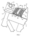
- an air bag module 17 is provided on the body frame 5 between the head pipe 6 and the fuel tank 10 for example, and the air bag module 17 is provided with an air bag housing 18, an air bag 19 housed in the air bag housing 18 and an inflator 20 that generates gas for inflating and extending the air bag 19.
- the air bag housing 18 is provided with a housing barrel 18a that can house the air bag 19 in a folded state and a flap 18b that closes an opening at the upper end of the housing barrel 18a, is formed by light material made of synthetic resin like a cap and the downside of the housing barrel 18a is attached to the body frame 5 by an attachment piece 21 fixed to the body frame 5.
- the flap 18b is coupled to the housing barrel 18a via a hinge 18c arranged in one location around the flap 18b, for example in one location on the side reverse to the fuel tank 10 and a weak part 18d arranged in a part except the hinge 18c around the flap 18b, and the weak part 18d is formed so that it can be easily burst.
- An opening 22 of the air bag 19 is airtightly closed by a connector 23 fixed to the attachment piece 21 and the inflator 20 is attached to the inside of the connector 23.
- a shock sensor such as an acceleration sensor is attached to the body frame 5, the inflator 20 is operated when the shock sensor detects shock equal to or exceeding a predetermined value and supplies high-pressure gas into the air bag 19.
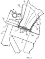
- the air bag 19 bursts the weak part 18d of the air bag housing 18, momentarily inflates and extends upward, opening the flap 18b as shown in Fig. 3 and a rider seated on the seat 12 is constrained by the inflated and extended air bag 19 from a forward direction.
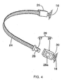
- the motorcycle is provided with the seat belt 24 wound onto the waist of the rider to constrain the rider on the seat 12 on the body 16 and as shown in Fig. 4, one end of the seat belt 24 is coupled to the body 16 via a retractor 25 provided with a locking function in emergency set so that the retractor is turned a locked state by the action of excessive impact caused by collision and others.
- a tongue 27 provided with a fitting hole 26 is fixed to the other end of the seat belt 24 and a buckle 28 forming coupling means 29 provided between the other end of the seat belt 24 and the body 16 together with the tongue 27 is provided on the side of the body 16.
- the other end of the seat belt 24 is coupled to the body 16 when the side of the buckle 28 is fitted to the fitting hole 26 by inserting the tongue 27 into the buckle 28, the fitting of the side of the buckle 28 to the fitting hole 26 is released by pressing an operating part 28a with which the buckle 28 is provided, and coupling between the other end of the seat belt 24 and the body 16 is released. That is, the coupling means 29 couples the other end of the seat belt 24 and the body 16 by the coupling by manual operation.
- an actuator 30 for releasing coupling without manual operation when the coupling means 29 is in a coupled state is provided, and the actuator 30 is actuated when predetermined time elapses since the air bag 19 is inflated and extended in the coupled state, for example when 0.5 second elapses since the inflator 20 is actuated and releases the coupling of the coupling means 29.
- one end of the seat belt 24 that can be wound onto the waist of the rider on the seat 12 is coupled to the body 16 via the retractor 25 provided with the locking function in emergency and the coupling means 29 in which coupling and the release of coupling can be switched manually and in the coupled state, coupling is automatically released when predetermined time (for example, 0.5 second) elapses since the air bag 19 is inflated and extended is provided between the other end of the seat belt 24 and the body 16.
- predetermined time for example, 0.5 second
- the retractor 25 is locked by keeping the coupling means 29 in the coupled state by manual operation when the air bag 19 is inflated and extended by the collision of the motorcycle and others, the rider is constrained by the seat belt 24 made tense when the retractor is locked, the rider is received by the inflated and extended air bag 19 and impact can be effectively relieved.
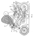
- the coupling means 29 automatically releases coupling as shown in Fig. 5 and the tongue 27 is withdrawn from the buckle 28 when predetermined time elapses since the air bag 19 is inflated and extended, the constraint of the rider by the seat belt 24 is released.
- Fig. 6 shows a second embodiment of the invention and the same reference number is allocated to a part corresponding to that in the first embodiment.
- an overturn detection sensor 31 formed by an inclination sensor or a lateral acceleration sensor is attached to the center in a direction of the width of the body 16 under the seat 12 and the overturn of the body 16 is detected by the overturn detection sensor 31.
- the coupling means 29 is configured so that it releases coupling when the overturn detection sensor 31 detects the overturn.
- the constraint of the rider on the body 16, which may cause a skid or secondary collision can be released.
- the inventions can be widely applied not only to the motorcycle described in the embodiments but to a compact vehicle such as a scooter-type motorcycle and a three-wheeled vehicle.
- one end of a seat belt 24 that can be wound onto the waist of a rider on a seat 12 is coupled to a body 16 via a retractor provided with a locking function in emergency, and coupling means 29 in which coupling and the release of coupling can be switched manually and in a coupled state, coupling is automatically released when predetermined time elapses since an air bag 19 is inflated and extended is provided between the other end of the seat belt 24 and the body 16.
Abstract
Description
- The present invention relates to a compact vehicle provided with a seat provided to the rear of a body and an air bag that can constrain a rider on the seat from a forward direction when the air bag is inflated and extended.
- Such a compact vehicle is disclosed in Japanese published unexamined patent application No. 2001-219884 for example.
- In a four-wheel vehicle, to enhance impact absorption effect by an inflated and extended air bag, a seat belt made tense by the action of impact is required to be used together and in a compact vehicle such as a motorcycle, it is also considered that the effect of an air bag can be more enhanced by using a seat belt disclosed in Japanese published unexamined patent application No. Hei8-239073. However, in the compact vehicle such as a motorcycle, secondary motion such as an overturn and a skid after collision and secondary collision may be caused and when such secondary motion is caused, it is desirable that constraint by a seat belt is released.
- The invention is made in view of such a situation and the object is to provide a compact vehicle in which to more enhance impact absorption effect by an air bag, a rider is constrained by a seat belt and when secondary motion is caused in relation to a body, the constraint of the rider can be released.
- To achieve the object, the invention according to Claim 1 is based upon a compact vehicle provided with a seat provided to the rear of a body and an air bag that can constrain a rider on the seat from a forward direction when the air bag is inflated and extended and is characterized in that one end of a seat belt which can be wound onto the waist of the rider on the seat is coupled to the body via a retractor provided with a locking function in emergency and a coupling means in which coupling and the release of coupling can be switched manually and in a coupled state, coupling is automatically released when predetermined time elapses since the air bag is inflated and extended is provided between the other end of the seat belt and the body.
- According to such configuration, when the air bag is inflated and extended because of the collision of the compact vehicle, the rider is constrained by the seat belt made tense when the retractor is locked by keeping the coupling means in the coupled state by manual operation and impact can be effectively relieved because the inflated and extended air bag receives the rider constrained by the seat belt. In addition, as the coupling of the coupling means is automatically released when predetermined time elapses since the air bag is inflated and extended, the constraint of the rider by the seat belt is released.
- As described above, according to the invention according to Claim 1, the inflated and extended air bag receives the rider constrained by the seat belt and impact can be effectively relieved respectively by keeping the coupling means in the coupled state by manual operation and in addition, when secondary motion is caused in relation to the body, the constraint of the rider on the body can be released.
- Besides, the invention according to
Claim 2 is based upon the configuration according to the invention according to Claim 1 and is characterized in that the coupling of the coupling means is released when an overturn detection sensor for detecting the overturn of the body detects the overturn, and according to such configuration, when the motorcycle individually overturns because of a cause except collision, the constraint of the rider on the body, which may cause a skid or secondary collision can be released. - Besides, according to the invention according to
Claim 2, when the motorcycle individually overturns because of a cause except collision, the constraint of the rider on the body, which may cause a skid or secondary collision can be released. - Embodiments of the invention shown in the attached drawings will be described below.
- Fig. 1 is a side view showing a motorcycle equivalent to a first embodiment;
- Fig. 2 is an enlarged longitudinal section viewed from
direction shown by an
arrow 2 in Fig. 1; - Fig. 3 is a sectional view corresponding to Fig. 2 when an air bag is inflated and extended;
- Fig. 4 shows the simple configuration of a seat belt;
- Fig. 5 is a side view showing the motorcycle in a state in which predetermined time elapses after the air bag is inflated and extended; and
- Fig. 6 is a side view showing a motorcycle equivalent to a second embodiment.
-
- Figs. 1 to 5 show a first embodiment of the invention,
- First as shown in Fig. 1, a
front fork 7 for supporting a front wheel WF is supported by ahead pipe 6 with which abody frame 5 of the motorcycle is provided at its front end so that the front fork can be steered and asteering handlebar 8 is attached to atop bridge 7a with which thefront fork 7 is provided on the upside of it. Aswing arm 9 is supported by the rear of thebody frame 5 so that the swing arm can be vertically oscillated and a rear wheel WR is supported by the rear end of theswing arm 9. - A
fuel tank 10 is mounted on a front half of thebody frame 5 and atandem type seat 12 arranged at the back of thefuel tank 10 is provided on aseat rail 11 with which thebody frame 5 is provided in the rear of the body frame. - Most of the
body frame 5 is covered with abody cover 15 made of synthetic resin and forming abody 16 together with thebody frame 5 and thebody cover 15 is composed of afront cowl 13 and arear cowl 14. - As shown in Fig. 2, an
air bag module 17 is provided on thebody frame 5 between thehead pipe 6 and thefuel tank 10 for example, and theair bag module 17 is provided with anair bag housing 18, anair bag 19 housed in theair bag housing 18 and aninflator 20 that generates gas for inflating and extending theair bag 19. - The
air bag housing 18 is provided with ahousing barrel 18a that can house theair bag 19 in a folded state and aflap 18b that closes an opening at the upper end of thehousing barrel 18a, is formed by light material made of synthetic resin like a cap and the downside of thehousing barrel 18a is attached to thebody frame 5 by anattachment piece 21 fixed to thebody frame 5. - The
flap 18b is coupled to thehousing barrel 18a via ahinge 18c arranged in one location around theflap 18b, for example in one location on the side reverse to thefuel tank 10 and aweak part 18d arranged in a part except thehinge 18c around theflap 18b, and theweak part 18d is formed so that it can be easily burst. - An
opening 22 of theair bag 19 is airtightly closed by aconnector 23 fixed to theattachment piece 21 and theinflator 20 is attached to the inside of theconnector 23. - A shock sensor (not shown) such as an acceleration sensor is attached to the
body frame 5, theinflator 20 is operated when the shock sensor detects shock equal to or exceeding a predetermined value and supplies high-pressure gas into theair bag 19. - When the high-pressure gas is supplied from the
inflator 20, theair bag 19 bursts theweak part 18d of theair bag housing 18, momentarily inflates and extends upward, opening theflap 18b as shown in Fig. 3 and a rider seated on theseat 12 is constrained by the inflated and extendedair bag 19 from a forward direction. - The motorcycle is provided with the
seat belt 24 wound onto the waist of the rider to constrain the rider on theseat 12 on thebody 16 and as shown in Fig. 4, one end of theseat belt 24 is coupled to thebody 16 via aretractor 25 provided with a locking function in emergency set so that the retractor is turned a locked state by the action of excessive impact caused by collision and others. - A
tongue 27 provided with afitting hole 26 is fixed to the other end of theseat belt 24 and abuckle 28 forming coupling means 29 provided between the other end of theseat belt 24 and thebody 16 together with thetongue 27 is provided on the side of thebody 16. The other end of theseat belt 24 is coupled to thebody 16 when the side of thebuckle 28 is fitted to thefitting hole 26 by inserting thetongue 27 into thebuckle 28, the fitting of the side of thebuckle 28 to thefitting hole 26 is released by pressing anoperating part 28a with which thebuckle 28 is provided, and coupling between the other end of theseat belt 24 and thebody 16 is released. That is, the coupling means 29 couples the other end of theseat belt 24 and thebody 16 by the coupling by manual operation. - In addition, on the side of the
buckle 28 of the coupling means 29, anactuator 30 for releasing coupling without manual operation when the coupling means 29 is in a coupled state is provided, and theactuator 30 is actuated when predetermined time elapses since theair bag 19 is inflated and extended in the coupled state, for example when 0.5 second elapses since theinflator 20 is actuated and releases the coupling of the coupling means 29. - Next, to explain the action of the first embodiment, one end of the
seat belt 24 that can be wound onto the waist of the rider on theseat 12 is coupled to thebody 16 via theretractor 25 provided with the locking function in emergency and the coupling means 29 in which coupling and the release of coupling can be switched manually and in the coupled state, coupling is automatically released when predetermined time (for example, 0.5 second) elapses since theair bag 19 is inflated and extended is provided between the other end of theseat belt 24 and thebody 16. - Therefore, as the
retractor 25 is locked by keeping the coupling means 29 in the coupled state by manual operation when theair bag 19 is inflated and extended by the collision of the motorcycle and others, the rider is constrained by theseat belt 24 made tense when the retractor is locked, the rider is received by the inflated and extendedair bag 19 and impact can be effectively relieved. - In addition, as the coupling means 29 automatically releases coupling as shown in Fig. 5 and the
tongue 27 is withdrawn from thebuckle 28 when predetermined time elapses since theair bag 19 is inflated and extended, the constraint of the rider by theseat belt 24 is released. - Fig. 6 shows a second embodiment of the invention and the same reference number is allocated to a part corresponding to that in the first embodiment.
- For example, an
overturn detection sensor 31 formed by an inclination sensor or a lateral acceleration sensor is attached to the center in a direction of the width of thebody 16 under theseat 12 and the overturn of thebody 16 is detected by theoverturn detection sensor 31. - In addition, the coupling means 29 is configured so that it releases coupling when the
overturn detection sensor 31 detects the overturn. - According to the second embodiment, when the motorcycle individually overturns because of a cause except collision, the constraint of the rider on the
body 16, which may cause a skid or secondary collision can be released. - The inventions can be widely applied not only to the motorcycle described in the embodiments but to a compact vehicle such as a scooter-type motorcycle and a three-wheeled vehicle.
- This is to constrain a rider by a seat belt to more enhance impact absorption effect by an air bag and to release the constraint of the rider when secondary motion is caused in relation to a body in a compact vehicle provided with a seat provided to the rear of the body and the air bag that can constrain the rider on the seat from a forward direction when the air bag is inflated and extended.
To achieve this, one end of aseat belt 24 that can be wound onto the waist of a rider on aseat 12 is coupled to abody 16 via a retractor provided with a locking function in emergency, and coupling means 29 in which coupling and the release of coupling can be switched manually and in a coupled state, coupling is automatically released when predetermined time elapses since anair bag 19 is inflated and extended is provided between the other end of theseat belt 24 and thebody 16.
Claims (2)
- A compact vehicle provided with a seat (12) provided to the rear of a body (16) and an air bag (19) that can constrain a rider on the seat (12) from a forward direction when the air bag is inflated and extended, wherein:one end of a seat belt (24) that can be wound onto the waist of the rider on the seat (12) is coupled to the body (16) via a retractor (25) provided with a locking function in emergency; andcoupling means (29) in which coupling and the release of coupling can be switched manually and the coupling is automatically released when predetermined time elapses since the air bag (19) is inflated and extended in a coupled state is provided between the other end of the seat belt (24) and the body (16).
- A compact vehicle according to Claim 1, wherein:the coupling means (29) releases coupling when an overturn detection sensor (31) for detecting the overturn of the body (16) detects the overturn.
Applications Claiming Priority (2)
| Application Number | Priority Date | Filing Date | Title |
|---|---|---|---|
| JP2002085680 | 2002-03-26 | ||
| JP2002085680A JP4357789B2 (en) | 2002-03-26 | 2002-03-26 | Motorcycle |
Publications (3)
| Publication Number | Publication Date |
|---|---|
| EP1348616A2 true EP1348616A2 (en) | 2003-10-01 |
| EP1348616A3 EP1348616A3 (en) | 2006-02-08 |
| EP1348616B1 EP1348616B1 (en) | 2006-12-13 |
Family
ID=27800431
Family Applications (1)
| Application Number | Title | Priority Date | Filing Date |
|---|---|---|---|
| EP03005954A Expired - Fee Related EP1348616B1 (en) | 2002-03-26 | 2003-03-17 | Compact vehicle |
Country Status (5)
| Country | Link |
|---|---|
| US (1) | US6793033B2 (en) |
| EP (1) | EP1348616B1 (en) |
| JP (1) | JP4357789B2 (en) |
| DE (1) | DE60310287T8 (en) |
| ES (1) | ES2276992T3 (en) |
Cited By (6)
| Publication number | Priority date | Publication date | Assignee | Title |
|---|---|---|---|---|
| WO2004092000A1 (en) * | 2003-04-16 | 2004-10-28 | Bayerische Motoren Werke Aktiengesellschaft | Motorcycle comprising a restraining device |
| DE102005045066A1 (en) * | 2004-09-29 | 2006-11-23 | Honda Motor Co., Ltd. | Driver restraint device |
| GB2427996A (en) * | 2005-07-08 | 2007-01-17 | Gerald Stretton | Safety system for a motorbike |
| CN103339024A (en) * | 2011-02-10 | 2013-10-02 | 绿伍控股有限公司 | A self-releasable safety belt |
| WO2015197416A1 (en) * | 2014-06-27 | 2015-12-30 | Laurent Doleac | Two-wheeled vehicle with operator-protection system |
| FR3038564A1 (en) * | 2015-07-08 | 2017-01-13 | Philippe Francois Girardi | DEVICE FOR COUPLING RETAINING MEANS FOR THE DRIVER AND PASSENGER(S) OF A VEHICLE WITH TWO OR MORE WHEELS, RECLINING OR NOT, MOTORIZED OR NOT |
Families Citing this family (18)
| Publication number | Priority date | Publication date | Assignee | Title |
|---|---|---|---|---|
| JP4129136B2 (en) * | 2002-03-01 | 2008-08-06 | 本田技研工業株式会社 | Motorcycle |
| JP4121112B2 (en) * | 2002-03-27 | 2008-07-23 | 本田技研工業株式会社 | Airbag device |
| JP4207753B2 (en) * | 2003-10-31 | 2009-01-14 | 株式会社デンソー | Resin housing structure for electrical circuit equipment |
| JP4609941B2 (en) * | 2005-09-07 | 2011-01-12 | 本田技研工業株式会社 | Airbag module mounting structure |
| US7789416B2 (en) * | 2005-09-08 | 2010-09-07 | Honda Motor Co., Ltd. | Air bag module cover structure |
| JP4627474B2 (en) * | 2005-09-30 | 2011-02-09 | 本田技研工業株式会社 | Airbag device |
| JP4958154B2 (en) * | 2006-11-29 | 2012-06-20 | 本田技研工業株式会社 | Motorcycle |
| JP5089972B2 (en) * | 2006-12-11 | 2012-12-05 | ヤマハ発動機株式会社 | Engine control device and saddle riding type vehicle |
| JP5439098B2 (en) * | 2009-09-15 | 2014-03-12 | 本田技研工業株式会社 | Crew restraint system for motorcycles |
| US8534422B2 (en) | 2011-06-29 | 2013-09-17 | Reechcraft, Inc. | Portable modular lift system |
| DE102012203640A1 (en) * | 2012-03-08 | 2013-09-12 | Robert Bosch Gmbh | A method of releasing a restraint device for sitting on a vehicle and a related vehicle |
| US8783722B1 (en) * | 2013-01-02 | 2014-07-22 | Gerald F. Gallo | Self-releasing vehicular harness |
| DE102013214298B4 (en) * | 2013-07-22 | 2022-08-25 | Robert Bosch Gmbh | A vehicle occupant restraint, a method of using such a vehicle occupant restraint, an article of clothing for a vehicle occupant and a safety system for releasably tying an occupant to a vehicle |
| DE102013217851A1 (en) * | 2013-09-06 | 2015-03-12 | Robert Bosch Gmbh | Safety system for a motorcycle and tripping method of a safety system |
| US9155340B2 (en) * | 2014-02-26 | 2015-10-13 | One Handit Bandit LLC | Rider and passenger stability belt |
| JP6646376B2 (en) * | 2015-07-31 | 2020-02-14 | Kyb株式会社 | Control device and suspension device for shock absorber |
| DE102016012572B4 (en) * | 2016-10-21 | 2022-10-13 | Oppermann Automotive Webbing Gmbh | Security system for a motorcycle |
| SG10201907758XA (en) | 2019-08-22 | 2021-03-30 | Green 5 Holding Pte Ltd | A self-releasable safety belt |
Citations (2)
| Publication number | Priority date | Publication date | Assignee | Title |
|---|---|---|---|---|
| JPH08239073A (en) | 1995-02-17 | 1996-09-17 | Bayerische Motoren Werke Ag | Safety device especially for bicycle |
| JP2001219884A (en) | 2000-02-09 | 2001-08-14 | Toyoda Gosei Co Ltd | Air bag device for saddle riding vehicle |
Family Cites Families (11)
| Publication number | Priority date | Publication date | Assignee | Title |
|---|---|---|---|---|
| GB2130150B (en) * | 1982-11-11 | 1986-08-06 | Transport The Minister Of | Vehicle safety system |
| JPH01128115U (en) * | 1988-02-25 | 1989-09-01 | ||
| JPH01317849A (en) * | 1988-06-20 | 1989-12-22 | Juichi Shimizu | Release adjusting device for seat belt with automatic release device |
| DE3904668A1 (en) * | 1989-02-16 | 1990-08-30 | Daimler Benz Ag | Passenger restraint system |
| IT1236087B (en) * | 1989-11-24 | 1992-12-22 | Gino Grassi | SAFETY BELT FOR VEHICLES WITH AUTOMATIC RELEASE SYSTEM |
| JP3685872B2 (en) * | 1996-06-11 | 2005-08-24 | 本田技研工業株式会社 | Pressure adjusting device for air bag in motorcycle |
| JP3685873B2 (en) * | 1996-06-19 | 2005-08-24 | 本田技研工業株式会社 | Airbag device for motorcycle |
| JP4052531B2 (en) * | 1998-03-30 | 2008-02-27 | 本田技研工業株式会社 | Airbag device for motorcycle |
| DE19836304A1 (en) * | 1998-08-11 | 1999-04-29 | Rohner Peter | Safety system for rider or pillion passenger of motorcycle |
| US6123166A (en) * | 1998-08-28 | 2000-09-26 | Trw Vehicle Safety Systems Inc. | Release apparatus for a seat belt buckle |
| JP3455872B2 (en) * | 1999-01-05 | 2003-10-14 | 重一 清水 | Seat belt unlocking device |
-
2002
- 2002-03-26 JP JP2002085680A patent/JP4357789B2/en not_active Expired - Fee Related
-
2003
- 2003-03-17 ES ES03005954T patent/ES2276992T3/en not_active Expired - Lifetime
- 2003-03-17 EP EP03005954A patent/EP1348616B1/en not_active Expired - Fee Related
- 2003-03-17 DE DE60310287T patent/DE60310287T8/en active Active
- 2003-03-21 US US10/392,961 patent/US6793033B2/en not_active Expired - Fee Related
Patent Citations (2)
| Publication number | Priority date | Publication date | Assignee | Title |
|---|---|---|---|---|
| JPH08239073A (en) | 1995-02-17 | 1996-09-17 | Bayerische Motoren Werke Ag | Safety device especially for bicycle |
| JP2001219884A (en) | 2000-02-09 | 2001-08-14 | Toyoda Gosei Co Ltd | Air bag device for saddle riding vehicle |
Cited By (12)
| Publication number | Priority date | Publication date | Assignee | Title |
|---|---|---|---|---|
| WO2004092000A1 (en) * | 2003-04-16 | 2004-10-28 | Bayerische Motoren Werke Aktiengesellschaft | Motorcycle comprising a restraining device |
| DE10317439A1 (en) * | 2003-04-16 | 2004-11-04 | Bayerische Motoren Werke Ag | Motorbike with restraint |
| DE102005045066A1 (en) * | 2004-09-29 | 2006-11-23 | Honda Motor Co., Ltd. | Driver restraint device |
| DE102005045066B4 (en) * | 2004-09-29 | 2007-04-12 | Honda Motor Co., Ltd. | Driver restraint device |
| GB2427996A (en) * | 2005-07-08 | 2007-01-17 | Gerald Stretton | Safety system for a motorbike |
| CN103339024A (en) * | 2011-02-10 | 2013-10-02 | 绿伍控股有限公司 | A self-releasable safety belt |
| EP2673184A1 (en) * | 2011-02-10 | 2013-12-18 | Green 5 Holding PTE Ltd | A self-releasable safety belt |
| EP2673184A4 (en) * | 2011-02-10 | 2014-07-23 | Green 5 Holding Pte Ltd | A self-releasable safety belt |
| AU2011358640B2 (en) * | 2011-02-10 | 2015-12-17 | Green 5 Holding Pte Ltd | A self-releasable safety belt |
| CN103339024B (en) * | 2011-02-10 | 2016-02-17 | 绿伍控股有限公司 | The safety strap that can automatically open |
| WO2015197416A1 (en) * | 2014-06-27 | 2015-12-30 | Laurent Doleac | Two-wheeled vehicle with operator-protection system |
| FR3038564A1 (en) * | 2015-07-08 | 2017-01-13 | Philippe Francois Girardi | DEVICE FOR COUPLING RETAINING MEANS FOR THE DRIVER AND PASSENGER(S) OF A VEHICLE WITH TWO OR MORE WHEELS, RECLINING OR NOT, MOTORIZED OR NOT |
Also Published As
| Publication number | Publication date |
|---|---|
| DE60310287T8 (en) | 2007-07-12 |
| DE60310287T2 (en) | 2007-03-29 |
| US6793033B2 (en) | 2004-09-21 |
| DE60310287D1 (en) | 2007-01-25 |
| JP2003276668A (en) | 2003-10-02 |
| EP1348616A3 (en) | 2006-02-08 |
| EP1348616B1 (en) | 2006-12-13 |
| ES2276992T3 (en) | 2007-07-01 |
| US20030230886A1 (en) | 2003-12-18 |
| JP4357789B2 (en) | 2009-11-04 |
Similar Documents
| Publication | Publication Date | Title |
|---|---|---|
| EP1348616B1 (en) | Compact vehicle | |
| EP1342653B1 (en) | Air bag apparatus for a scooter type motorcycle | |
| EP1668999B1 (en) | Airbag apparatus for a vehicle passenger | |
| US7168732B2 (en) | Compact vehicle | |
| US6971666B2 (en) | Airbag apparatus for a small size vehicle | |
| US7390014B2 (en) | Protecting device for a pedestrian or the like | |
| US7648159B2 (en) | Airbag apparatus, saddle-type vehicle with airbag apparatus | |
| US7549663B2 (en) | Airbag device for pedestrian | |
| JP4588904B2 (en) | Motorcycle airbag structure | |
| US11364965B2 (en) | Saddle riding vehicle airbag device | |
| JP4633910B2 (en) | Airbag device for motorcycle | |
| WO2019207775A1 (en) | Air bag device for saddled vehicle | |
| JP4647819B2 (en) | Vehicle occupant protection device | |
| US7198287B2 (en) | Airbag device and motorcycle with the airbag device | |
| US20070170702A1 (en) | Airbag System and Motorcycle with Airbag System | |
| JP4129138B2 (en) | Airbag device for motorcycle | |
| EP1348615A2 (en) | On-vehicle airbag apparatus | |
| WO2018221179A1 (en) | Airbag device for saddle-type vehicle | |
| EP1236621B1 (en) | Vehicular passive safety device | |
| US7226074B2 (en) | Airbag apparatus, motorcycle with airbag apparatus | |
| JP6964187B2 (en) | Airbag device for saddle-riding vehicles | |
| JP4052850B2 (en) | Airbag device for small vehicle | |
| JP2003306184A (en) | Air bag device | |
| CN114514166A (en) | Saddle-ride type vehicle | |
| WO2023119845A1 (en) | Airbag device for motorcycle |
Legal Events
| Date | Code | Title | Description |
|---|---|---|---|
| PUAI | Public reference made under article 153(3) epc to a published international application that has entered the european phase |
Free format text: ORIGINAL CODE: 0009012 |
|
| AK | Designated contracting states |
Kind code of ref document: A2 Designated state(s): AT BE BG CH CY CZ DE DK EE ES FI FR GB GR HU IE IT LI LU MC NL PT RO SE SI SK TR |
|
| AX | Request for extension of the european patent |
Extension state: AL LT LV MK |
|
| PUAL | Search report despatched |
Free format text: ORIGINAL CODE: 0009013 |
|
| AK | Designated contracting states |
Kind code of ref document: A3 Designated state(s): AT BE BG CH CY CZ DE DK EE ES FI FR GB GR HU IE IT LI LU MC NL PT RO SE SI SK TR |
|
| AX | Request for extension of the european patent |
Extension state: AL LT LV MK |
|
| 17P | Request for examination filed |
Effective date: 20060224 |
|
| GRAP | Despatch of communication of intention to grant a patent |
Free format text: ORIGINAL CODE: EPIDOSNIGR1 |
|
| AKX | Designation fees paid |
Designated state(s): DE ES IT |
|
| GRAS | Grant fee paid |
Free format text: ORIGINAL CODE: EPIDOSNIGR3 |
|
| GRAA | (expected) grant |
Free format text: ORIGINAL CODE: 0009210 |
|
| AK | Designated contracting states |
Kind code of ref document: B1 Designated state(s): DE ES IT |
|
| REF | Corresponds to: |
Ref document number: 60310287 Country of ref document: DE Date of ref document: 20070125 Kind code of ref document: P |
|
| REG | Reference to a national code |
Ref country code: ES Ref legal event code: FG2A Ref document number: 2276992 Country of ref document: ES Kind code of ref document: T3 |
|
| PLBE | No opposition filed within time limit |
Free format text: ORIGINAL CODE: 0009261 |
|
| STAA | Information on the status of an ep patent application or granted ep patent |
Free format text: STATUS: NO OPPOSITION FILED WITHIN TIME LIMIT |
|
| 26N | No opposition filed |
Effective date: 20070914 |
|
| PGFP | Annual fee paid to national office [announced via postgrant information from national office to epo] |
Ref country code: IT Payment date: 20100320 Year of fee payment: 8 |
|
| PGFP | Annual fee paid to national office [announced via postgrant information from national office to epo] |
Ref country code: ES Payment date: 20100408 Year of fee payment: 8 |
|
| PGFP | Annual fee paid to national office [announced via postgrant information from national office to epo] |
Ref country code: DE Payment date: 20100422 Year of fee payment: 8 |
|
| PG25 | Lapsed in a contracting state [announced via postgrant information from national office to epo] |
Ref country code: DE Free format text: LAPSE BECAUSE OF NON-PAYMENT OF DUE FEES Effective date: 20111001 |
|
| REG | Reference to a national code |
Ref country code: DE Ref legal event code: R119 Ref document number: 60310287 Country of ref document: DE Effective date: 20111001 |
|
| PG25 | Lapsed in a contracting state [announced via postgrant information from national office to epo] |
Ref country code: IT Free format text: LAPSE BECAUSE OF NON-PAYMENT OF DUE FEES Effective date: 20110317 |
|
| REG | Reference to a national code |
Ref country code: ES Ref legal event code: FD2A Effective date: 20120509 |
|
| PG25 | Lapsed in a contracting state [announced via postgrant information from national office to epo] |
Ref country code: ES Free format text: LAPSE BECAUSE OF NON-PAYMENT OF DUE FEES Effective date: 20110318 |