EP1348604B1 - Bloc sanitaire pour véhicule, notamment ferroviaire - Google Patents
Bloc sanitaire pour véhicule, notamment ferroviaire Download PDFInfo
- Publication number
- EP1348604B1 EP1348604B1 EP03290508A EP03290508A EP1348604B1 EP 1348604 B1 EP1348604 B1 EP 1348604B1 EP 03290508 A EP03290508 A EP 03290508A EP 03290508 A EP03290508 A EP 03290508A EP 1348604 B1 EP1348604 B1 EP 1348604B1
- Authority
- EP
- European Patent Office
- Prior art keywords
- cabin
- sanitary unit
- wall
- vehicle
- template
- Prior art date
- Legal status (The legal status is an assumption and is not a legal conclusion. Google has not performed a legal analysis and makes no representation as to the accuracy of the status listed.)
- Expired - Lifetime
Links
Images

Classifications
-
- A—HUMAN NECESSITIES
- A47—FURNITURE; DOMESTIC ARTICLES OR APPLIANCES; COFFEE MILLS; SPICE MILLS; SUCTION CLEANERS IN GENERAL
- A47K—SANITARY EQUIPMENT; ACCESSORIES THEREFOR, e.g. TOILET ACCESSORIES
- A47K4/00—Combinations of baths, showers, sinks, wash-basins, closets, or urinals, not covered by a single other group of this subclass
-
- B—PERFORMING OPERATIONS; TRANSPORTING
- B60—VEHICLES IN GENERAL
- B60R—VEHICLES, VEHICLE FITTINGS, OR VEHICLE PARTS, NOT OTHERWISE PROVIDED FOR
- B60R15/00—Arrangements or adaptations of sanitation devices
-
- B—PERFORMING OPERATIONS; TRANSPORTING
- B60—VEHICLES IN GENERAL
- B60R—VEHICLES, VEHICLE FITTINGS, OR VEHICLE PARTS, NOT OTHERWISE PROVIDED FOR
- B60R15/00—Arrangements or adaptations of sanitation devices
- B60R15/02—Washing facilities
-
- B—PERFORMING OPERATIONS; TRANSPORTING
- B60—VEHICLES IN GENERAL
- B60R—VEHICLES, VEHICLE FITTINGS, OR VEHICLE PARTS, NOT OTHERWISE PROVIDED FOR
- B60R15/00—Arrangements or adaptations of sanitation devices
- B60R15/04—Toilet facilities
-
- B—PERFORMING OPERATIONS; TRANSPORTING
- B61—RAILWAYS
- B61D—BODY DETAILS OR KINDS OF RAILWAY VEHICLES
- B61D35/00—Sanitation
-
- B—PERFORMING OPERATIONS; TRANSPORTING
- B63—SHIPS OR OTHER WATERBORNE VESSELS; RELATED EQUIPMENT
- B63B—SHIPS OR OTHER WATERBORNE VESSELS; EQUIPMENT FOR SHIPPING
- B63B29/00—Accommodation for crew or passengers not otherwise provided for
- B63B29/02—Cabins or other living spaces; Construction or arrangement thereof
- B63B29/14—Closet or like flushing arrangements; Washing or bathing facilities peculiar to ships
Definitions
- the invention relates to a toilet block for vehicles, including rail, having a cabin with at least one toilet bowl or sink.
- a toilet block incorporating a wastewater holding tank in one of its side walls and having a ceiling supporting a clear water tank.
- a toilet block has the advantage of having tanks that do not encumber the subframe of the vehicle but has the disadvantage of requiring walls having a sufficiently rigid structure to support the clear water tank, the last being more, given its layout, low capacity and necessarily necessarily connected to a water supply circuit of the train, which complicates its assembly.
- Such a toilet block also has the disadvantage of having a cabin whose ceiling height is limited by the size of the clear water tank.
- the arrangement of such a toilet block is such that, for a given external template, the holding tank of wastewater implanted in one of the walls reduces the useful width of the cabin.
- an object of the present invention is to overcome these drawbacks by proposing a sanitary block with the optimized layout that embeds all the equipment necessary for its operation and this without significant reduction of the internal ergonomic space of the cabin.
- the invention relates to a toilet block for a vehicle, including rail, comprising a cabin provided with at least one toilet bowl or sink, the sanitary block having externally a substantially parallelepipedal template adapted for s' insert into a housing provided in the vehicle, the toilet block incorporating inside the template at least one clear water tank and a wastewater holding tank necessary for the operation of the toilet block, characterized in that the tanks of clear water and water retention each of the wastewater tanks are vertically arranged at an angle of the parallelepipedal jig, the clear water and wastewater holding tanks having on one side a wedge shape matching the angle of the parallelepipedal jig and, on the opposite side, a facing wall towards the cabin substantially matching the shape of the cabin.
- the figure 1 presents a toilet block intended to be installed in a railway vehicle.
- the sanitary block comprises externally a jig 1 in the form of a rectangular parallelepiped, delimited by a set of side walls 11, this jig 1 being adapted to fit into a receiving housing provided on the railway vehicle.
- the toilet block comprises a cabin 3 delimited by two internal partitions 3a of arcuate shape, these internal partitions 3a being arranged slightly set back from the side walls 11 of the jig 1.
- the internal partitions 3a are assembled against each other at two vertical edges 31 disposed in the vicinity of two opposite corners of the parallelepipedal jig 1, each internal partition 3a extending, close to the ridges 31, parallel to the wall side 11 nearest.
- the internal partitions 3a have, opposite the other two corners of the jig 1, a shape of a circular arc of high radius so that a large space results between the arcuate part of the internal partitions 3a and the side walls 11 the closest.
- a clear water tank 4 and a wastewater holding tank 5 are each arranged in an angle of the parallelepipedal jig 1, at the level of the two spaces released by the arcuate portions of the internal partitions 3a. .
- These tanks 4 and 5 extend vertically over substantially the entire height of the jig 1 and have on one side a wedge shape matching the angle formed by the side walls 11 and on the opposite a wall 4a, 5a conforming to the shape of the partition 3a in an arc delimiting the cabin 3.
- tanks for clear water 4 and waste water retention 5 are connected, in a manner known per se, to a toilet bowl 2 which is arranged in the cabin 3 against the arcuate part of one of the two partitions. internal 3a, the other wall receiving, along its straight portion, a sink 6 carried by a shelf, the latter also extending partially on the arcuate portion of the partition 3a.
- An opening, closed by a door 7, is formed in the straight portion of the partition 3a disposed substantially opposite the wash basin 6 to allow access to the cabin 3.
- Elements not shown on the Figures 1 and 2 such as pipes, circulation pumps and heaters, necessary for the proper operation of the toilet block, are advantageously arranged in the resulting space between the internal partitions 3a of the cabin 3 and the side walls 11 of the template.
- the side walls 11 comprise access hatches for the maintenance of these elements without disassembly of the toilet block.
- Such a toilet block has the advantage of shipping, in a given template, all the elements necessary for the operation of the toilet block without significantly affecting the internal ergonomic space of the cabin of the toilet block.
- Such a toilet block also has the advantage of being in the form of an independent module that can be pre-assembled and tested outside the vehicle. Thus, such a toilet block can be inserted in one block in the rail vehicle.
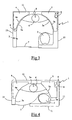
- the figure 3 represents an alternative embodiment of the invention in which the toilet block externally retains a parallelepipedal jig 1, similar to that of the figure 1 delimited by side walls 11.
- This variant is different from the sanitary block of Figures 1 and 2 in that the clear water tanks 4 and the waste water holding tanks 5 are arranged in two angles of the parallelepipedal jig 1 situated on the same side, the tanks 4 and 5 having on one side a wedge shape wedging the angle of the jig 1 and opposite a wall 4a, 5a marrying an internal partition 3a locally defining the cabin 3 of the toilet block.
- the internal partitions 3a defining the cabin 3 of the toilet block extend in an arc in front of the corners occupied by the tanks 4 and 5 and extend, outside these zones, parallel to the side walls 11, being arranged slightly behind the latter.
- the cabin 3 comprises in the usual way a sink 6, the latter being here disposed against the internal partition 3a extending between the two tanks 4 and 5, the inner partition 3a opposite the sink 6 receiving on the one hand a toilet bowl 2 in a corner and on the other hand a sliding door 7 allowing access to the cabin 3.
- Elements 8 such as piping, circulation pumps and heaters necessary for the proper operation of the toilet block are arranged in the resulting space between the partitions 3a of the cabin 3 and the side walls 11 of the jig 1.
- Such an embodiment variant has the advantage of ensuring optimal ergonomics in a limited volume.
- the figure 4 presents another variant embodiment of the invention in which the parallelepipedal jig 1 of the sanitary block, delimited by the side walls 11, is of reduced size.
- the clear water tanks 4 and the wastewater holding tanks 5 are arranged in two angles of the parallelepipedal jig 1 situated on the same side, each tank 4,5 having on one side a wedge shape matching the 1 angle of the jig and the opposite a wall 4a, 5a shaped arc constituting an internal partition of the cabin 3.
- the cabin 3 is delimited between the two tanks 4 and 5 by an internal partition 3a disposed in the extension of the walls 4a, 5a in the shape of a circular arc and is delimited laterally by internal partitions 3a extending substantially parallel to the side walls 11.
- a sink 6 is disposed against the internal partition 3a extending between the two reservoirs 4 and 5, the opposite internal partition 3a receiving on the one hand a toilet bowl 2 and on the other hand an arcuate sliding door 7 opening in a kinematic arcuate.
- Elements 8 such as pipes, circulation pumps and heaters, necessary for the proper operation of the toilet block are, as in the other embodiments, arranged in the resulting space between the internal partitions 3a and the side walls 11 of the template 1.
Landscapes
- Health & Medical Sciences (AREA)
- Public Health (AREA)
- Engineering & Computer Science (AREA)
- Mechanical Engineering (AREA)
- Epidemiology (AREA)
- General Health & Medical Sciences (AREA)
- Chemical & Material Sciences (AREA)
- Combustion & Propulsion (AREA)
- Ocean & Marine Engineering (AREA)
- Vehicle Waterproofing, Decoration, And Sanitation Devices (AREA)
- Sanitary Device For Flush Toilet (AREA)
- Residential Or Office Buildings (AREA)
- Toilet Supplies (AREA)
- Fuel Cell (AREA)
- Vehicle Interior And Exterior Ornaments, Soundproofing, And Insulation (AREA)
Description
- L'invention se rapporte à un bloc sanitaire pour véhicule, notamment ferroviaire, présentant une cabine munie d'au moins une cuvette de WC ou d'un lavabo.
- Il est courant d'équiper les véhicules ferroviaires de blocs sanitaires comportant une cabine munie d'équipements tels qu'une cuvette de WC ou un lavabo. De tels blocs sanitaires sont habituellement raccordés à des réservoirs d'eau claire et de rétention des eaux usées disposés sous le châssis du véhicule. Un tel agencement avec les réservoirs séparés et éloignés du bloc sanitaire présente cependant l'inconvénient de compliquer le montage du bloc sanitaire, en mettant en oeuvre de nombreux raccordements, mais également d'encombrer le sous-châssis du véhicule avec les réservoirs.
- Il est connu, du
brevet US 6 101 766 (préambule de la revendication 1), un bloc sanitaire intégrant un réservoir de rétention des eaux usées dans l'une de ses parois latérales et présentant un plafond supportant un réservoir d'eau claire. Un tel bloc sanitaire présente l'avantage d'avoir des réservoirs qui n'encombrent pas le sous-châssis du véhicule mais présente toutefois l'inconvénient de nécessiter des parois présentant une structure suffisamment rigide pour pouvoir supporter le réservoir d'eau claire, ce dernier étant de plus, compte tenu de sa disposition, de faible capacité et en conséquence nécessairement raccordé à un circuit d'alimentation en eau du train, ce qui complique son montage. Un tel bloc sanitaire présente également l'inconvénient d'avoir une cabine dont la hauteur sous plafond est limitée par la taille du réservoir d'eau claire. Enfin, l'agencement d'un tel bloc sanitaire est tel que, pour un gabarit extérieur donné, le réservoir de rétention des eaux usées implanté dans l'une des parois réduit d'autant la largeur utile de la cabine. - Aussi, un but de la présente invention est de remédier à ces inconvénients en proposant un bloc sanitaire à l'agencement optimisé qui embarque tous les équipements nécessaires à son fonctionnement et ceci sans réduction notable de l'espace ergonomique interne de la cabine.
- A cet effet, l'invention a pour objet un bloc sanitaire pour véhicule, notamment ferroviaire, comportant une cabine munie d'au moins une cuvette de WC ou d'un lavabo, le bloc sanitaire présentant extérieurement un gabarit sensiblement parallélépipédique adapté pour s'insérer dans un logement d'accueil prévu dans le véhicule, le bloc sanitaire intégrant à l'intérieur du gabarit au moins un réservoir d'eau claire et un réservoir de rétention des eaux usées nécessaires au fonctionnement du bloc sanitaire, caractérisé en ce que les réservoirs d'eau claire et de rétention des eaux usées sont disposés chacun verticalement dans un angle du gabarit parallélépipédique, les réservoirs d'eau claire et de rétention des eaux usées présentant d'un côté une forme en coin épousant l'angle du gabarit parallélépipédique et, à l'opposé, une paroi orientée vers la cabine épousant sensiblement la forme de la cabine.
- Selon des modes particuliers de réalisation, le bloc sanitaire selon l'invention peut comprendre l'une ou plusieurs des caractéristiques suivantes prises isolément ou selon toutes les combinaisons techniquement possibles :
- la paroi du réservoir orientée vers la cabine présente une forme arrondie ;
- la paroi du réservoir orientée vers la cabine est en arc de cercle ;
- la paroi du réservoir orientée vers la cabine épouse une cloison délimitant la cabine ;
- la paroi du réservoir orientée vers la cabine constitue localement une cloison délimitant la cabine ;
- chacun des réservoirs d'eau claire et d'eaux usées s'étend sensiblement sur toute la hauteur du gabarit du bloc sanitaire.
- On comprendra mieux les buts, aspects et avantages de la présente invention, d'après la description donnée ci-après de plusieurs modes de réalisation de l'invention, présentés à titre d'exemples non limitatifs, en se référant aux dessins annexés, dans lesquels :
- la
figure 1 est une vue en perspective, partiellement arrachée, d'un bloc sanitaire selon un mode particulier de réalisation de l'invention ; - la
figure 2 est une vue de dessus du bloc sanitaire de lafigure 1 ; - la
figure 3 est une vue de dessus d'une variante de réalisation du bloc sanitaire selon l'invention. ; - la
figure 4 est une vue de dessus d'une autre variante de réalisation du bloc sanitaire selon l'invention. - Pour faciliter la lecture du dessin, seuls les éléments nécessaires à la compréhension de l'invention ont été représentés.
- La
figure 1 présente un bloc sanitaire destiné à être installé dans un véhicule ferroviaire. Conformément à cette figure, le bloc sanitaire comporte extérieurement un gabarit 1 en forme de parallélépipède rectangle, délimité par un ensemble de parois latérales 11, ce gabarit 1 étant adapté pour s'insérer dans un logement d'accueil prévu sur le véhicule ferroviaire. A l'intérieur du gabarit 1, le bloc sanitaire comporte une cabine 3 délimitée par deux cloisons internes 3a de forme arquée, ces cloisons internes 3a étant disposées légèrement en retrait des parois latérales 11 du gabarit 1. - Les cloisons internes 3a sont assemblées l'une contre l'autre au niveau de deux arêtes verticales 31 disposées au voisinage de deux coins opposés du gabarit 1 parallélépipédique, chaque cloison interne 3a s'étendant, à proximité des arêtes 31, parallèlement à la paroi latérale 11 la plus proche. Les cloisons internes 3a présentent, en regard des deux autres coins du gabarit 1, une forme en arc de cercle de fort rayon de sorte qu'il résulte un espace important entre la partie en arc de cercle des cloisons internes 3a et les parois latérales 11 les plus proches.
- Conformément à l'invention, un réservoir d'eau claire 4 et un réservoir de rétention des eaux usées 5 sont disposés chacun dans un angle du gabarit 1 parallélépipédique, au niveau des deux espaces libérés par les parties en arc de cercle des cloisons internes 3a. Ces réservoirs 4 et 5 s'étendent verticalement sur sensiblement toute la hauteur du gabarit 1 et présentent d'un côté une forme en coin épousant l'angle formé par les parois latérales 11 et à l'opposé une paroi 4a,5a épousant la forme de la cloison 3a en arc de cercle délimitant la cabine 3.
- Ces réservoirs d'eau claire 4 et de rétention des eaux usées 5 sont reliés, de manière connue en soi, à une cuvette 2 de WC qui est disposée dans la cabine 3 contre la partie en arc de cercle de l'une des deux cloisons internes 3a, l'autre cloison recevant, le long de sa partie rectiligne, un lavabo 6 porté par une tablette, cette dernière s'étendant également partiellement sur la partie en arc de cercle de la cloison 3a. Une ouverture, fermée par une porte 7, est ménagée dans la partie rectiligne de la cloison 3a disposée sensiblement en regard du lavabo 6 afin de permettre l'accès à la cabine 3.
- Des éléments non représentés sur les
figures 1 et 2 , tels que tuyauteries, pompes de circulation et réchauffeurs, nécessaires au bon fonctionnement du bloc sanitaire, sont avantageusement disposés dans l'espace résultant entre les cloisons internes 3a de la cabine 3 et les parois latérales 11 du gabarit. De manière avantageuse les parois latérales 11 comportent des trappes d'accès permettant la maintenance de ces éléments sans démontage du bloc sanitaire. - Un tel bloc sanitaire présente l'avantage d'embarquer, dans un gabarit donné, l'ensemble des éléments nécessaires au fonctionnement du bloc sanitaire sans nuire notablement à l'espace ergonomique interne de la cabine du bloc sanitaire. Un tel bloc sanitaire présente également l'avantage d'être sous la forme d'un module indépendant qui peut être préassemblé et testé en dehors du véhicule. Ainsi, un tel bloc sanitaire peut être inséré d'un seul bloc dans le véhicule ferroviaire.
- La
figure 3 représente une variante de réalisation de l'invention dans laquelle le bloc sanitaire conserve extérieurement un gabarit 1 parallélépipédique, similaire à celui de lafigure 1 , délimités par des parois latérales 11. Cette variante se différentie du bloc sanitaire desfigures 1 et 2 en ce que les réservoirs d'eau claire 4 et de rétention des eaux usées 5 sont disposés dans deux angles du gabarit parallélépipédique 1 situés sur un même côté, les réservoirs 4 et 5 présentant d'un côté une forme en coin épousant l'angle du gabarit 1 et à l'opposé une paroi 4a,5a épousant une cloison interne 3a délimitant localement la cabine 3 du bloc sanitaire. Conformément à lafigure 3 , les cloisons internes 3a délimitant la cabine 3 du bloc sanitaire s'étendent en arc de cercle devant les angles occupés par les réservoirs 4 et 5 et s'étendent, en dehors de ces zones, parallèlement aux parois latérales 11, en étant disposées légèrement en retrait de ces dernières. - La cabine 3 comporte de manière habituelle un lavabo 6, ce dernier étant ici disposé contre la cloison interne 3a s'étendant entre les deux réservoirs 4 et 5, la cloison interne 3a opposée au lavabo 6 recevant d'une part une cuvette 2 de WC dans un coin et d'autre part une porte coulissante 7 permettant l'accès à la cabine 3. Des éléments 8 tels que tuyauteries, pompes de circulation et réchauffeurs nécessaires au bon fonctionnement du bloc sanitaire sont disposés dans l'espace résultant entre les cloisons internes 3a de la cabine 3 et les parois latérales 11 du gabarit 1.
- Une telle variante de réalisation présente l'avantage d'assurer une ergonomie optimale dans un volume limité.
- La
figure 4 présente une autre variante de réalisation de l'invention dans laquelle le gabarit 1 parallélépipédique du bloc sanitaire, délimité par les parois latérales 11, est de dimension réduite. Dans cette variante, les réservoirs d'eau claire 4 et de rétention des eaux usées 5 sont disposés dans deux angles du gabarit parallélépipédique 1 situés d'un même coté, chaque réservoir 4,5 présentant d'un côté une forme en coin épousant l'angle du gabarit 1 et à l'opposé une paroi 4a,5a en forme d'arc de cercle constituant une cloison interne de la cabine 3. La cabine 3 est délimitée entre les deux réservoirs 4 et 5 par une cloison interne 3a disposée dans le prolongement des parois 4a,5a en forme d'arc de cercle et est délimitée latéralement par des cloisons internes 3a s'étendant sensiblement parallèlement aux parois latérales 11. Un lavabo 6 est disposé contre la cloison interne 3a s'étendant entre les deux réservoirs 4 et 5, la cloison interne 3a opposée recevant d'une part une cuvette 2 de WC et d'autre part une porte coulissante 7 arquée s'ouvrant suivant une cinématique en arc de cercle. - Des éléments 8, tels que tuyauteries, pompes de circulation et réchauffeurs, nécessaires au bon fonctionnement du bloc sanitaire sont, tout comme dans les autres modes de réalisation, disposés dans l'espace résultant entre les cloisons internes 3a et les parois latérales 11 du gabarit 1.
- Bien entendu, l'invention n'est nullement limitée aux modes de réalisation décrits et illustrés qui n'ont été donnés qu'à titre d'exemple. Des modifications restent possibles, notamment du point de vue de la constitution des divers éléments ou par substitution d'équivalents techniques, sans sortir pour autant du domaine de protection de l'invention.
Claims (6)
- Bloc sanitaire pour véhicule, notamment ferroviaire, comportant une cabine (3) munie d'au moins une cuvette de WC (2) ou d'un lavabo (6), ledit bloc sanitaire présentant extérieurement un gabarit (1) sensiblement parallélépipédique adapté pour s'insérer dans un logement d'accueil prévu dans ledit véhicule, ledit bloc sanitaire intégrant à l'intérieur dudit gabarit (1) au moins un réservoir d'eau claire (4) et un réservoir de rétention d'eaux usées (5), caractérisé en ce que lesdits réservoirs d'eau claire (4) et de rétention des eaux usées (5) sont disposés chacun verticalement dans un angle du gabarit (1) parallélépipédique, lesdits réservoirs d'eau claire (4) et de rétention des eaux usées (5) présentant d'un côté une forme en coin épousant l'angle du gabarit (1) parallélépipédique et, à l'opposé, une paroi (4a, 5a) orientée vers la cabine (3) épousant sensiblement la forme de ladite cabine (3).
- Bloc sanitaire selon la revendication 1, caractérisé en ce que la paroi (4a, 5a) présente une forme arrondie.
- Bloc sanitaire selon la revendication 2, caractérisé en ce que la paroi (4a, 5a) est en arc de cercle.
- Bloc sanitaire selon l'une quelconque des revendications 1 à 3, caractérisé en ce que la paroi (4a, 5a) épouse une cloison (3a) délimitant localement la cabine (3).
- Bloc sanitaire selon l'une quelconque des revendications 1 à 3, caractérisé en ce que ladite paroi (4a, 5a) constitue localement une cloison délimitant la cabine (3).
- Bloc sanitaire selon l'une quelconque des revendications 1 à 5, caractérisé en ce que chacun desdits réservoirs d'eau claire (4) et d'eaux usées (5) s'étend sur sensiblement toute la hauteur du gabarit (1) du bloc sanitaire.
Applications Claiming Priority (2)
| Application Number | Priority Date | Filing Date | Title |
|---|---|---|---|
| FR0203911 | 2002-03-28 | ||
| FR0203911A FR2837768B1 (fr) | 2002-03-28 | 2002-03-28 | Bloc sanitaire pour vehicule, notamment ferroviaire |
Publications (3)
| Publication Number | Publication Date |
|---|---|
| EP1348604A1 EP1348604A1 (fr) | 2003-10-01 |
| EP1348604B1 true EP1348604B1 (fr) | 2008-05-21 |
| EP1348604B8 EP1348604B8 (fr) | 2008-09-10 |
Family
ID=27799280
Family Applications (1)
| Application Number | Title | Priority Date | Filing Date |
|---|---|---|---|
| EP03290508A Expired - Lifetime EP1348604B8 (fr) | 2002-03-28 | 2003-03-04 | Bloc sanitaire pour véhicule, notamment ferroviaire |
Country Status (12)
| Country | Link |
|---|---|
| US (1) | US6823538B2 (fr) |
| EP (1) | EP1348604B8 (fr) |
| JP (1) | JP2003327118A (fr) |
| CN (1) | CN1319794C (fr) |
| AT (1) | ATE396098T1 (fr) |
| AU (1) | AU2003201018B2 (fr) |
| CA (1) | CA2423216C (fr) |
| DE (1) | DE60321072D1 (fr) |
| ES (1) | ES2305411T3 (fr) |
| FR (1) | FR2837768B1 (fr) |
| PT (1) | PT1348604E (fr) |
| TW (1) | TWI287516B (fr) |
Cited By (1)
| Publication number | Priority date | Publication date | Assignee | Title |
|---|---|---|---|---|
| DE102008032651A1 (de) * | 2008-07-10 | 2010-01-21 | Siemens Aktiengesellschaft | Schienenfahrzeug mit fahrzeugseitig entleerbarem Abwassertank |
Families Citing this family (12)
| Publication number | Priority date | Publication date | Assignee | Title |
|---|---|---|---|---|
| JP2007089780A (ja) * | 2005-09-28 | 2007-04-12 | Sumitomo Forestry Co Ltd | トイレット |
| US20080289099A1 (en) * | 2007-05-10 | 2008-11-27 | Skinner Jerald P | Portable disability bath |
| FR2935946B1 (fr) * | 2008-09-18 | 2010-10-29 | Sncf | Bloc de compartiment de toilettes |
| DE102008064586A1 (de) * | 2008-12-23 | 2010-07-01 | Siemens Aktiengesellschaft | Vakuumtoiletten-Einrichtung für einen Eisenbahnwagen |
| CN102762455B (zh) * | 2010-02-19 | 2016-05-18 | 空中客车德国运营有限责任公司 | 用于交通工具的盥洗室装置 |
| DE102010037687C5 (de) * | 2010-09-21 | 2017-03-09 | Satek Gmbh | Sanitärkabine |
| US9708062B2 (en) * | 2011-04-18 | 2017-07-18 | C Series Aircraft Limited Partnership | Aircraft lavatory for a person with reduced mobility |
| KR101171273B1 (ko) | 2012-03-30 | 2012-08-06 | 흥일기업주식회사 | 열차용 화장실 모듈 |
| SE536645C2 (sv) * | 2012-09-05 | 2014-04-29 | Outback Capital Man Ab | Toalettarrangemang i husvagn eller husbil |
| EP3608226B1 (fr) | 2013-11-15 | 2024-01-03 | Airbus Operations GmbH | Agencement de toilette pour véhicule |
| DE102018103099A1 (de) * | 2018-02-12 | 2019-08-14 | Airbus Operations Gmbh | Kabinenmodul mit Sanitäreinheit |
| EP3620596B1 (fr) * | 2018-09-06 | 2020-07-29 | ADCO Umweltdienste Holding GmbH | Cabine sanitaire, en particulier cabine de toilettes |
Family Cites Families (10)
| Publication number | Priority date | Publication date | Assignee | Title |
|---|---|---|---|---|
| US2817846A (en) * | 1956-05-03 | 1957-12-31 | Robert J Stift | Mobile comfort station |
| US2817091A (en) * | 1957-05-22 | 1957-12-24 | American Trailer Co Inc | Mobile sanitary trailer |
| US3594825A (en) * | 1969-02-19 | 1971-07-27 | Standard Products Co | Water circulation system |
| DE2448980A1 (de) * | 1974-10-15 | 1976-04-22 | Horst Warneke | Vorfabrizierte, transportable nasszelle, vorzugsweise baderaum, fuer schiffe |
| US4718131A (en) * | 1986-07-28 | 1988-01-12 | Toto Ltd. | Sanitary facility unit |
| CN2037386U (zh) * | 1988-08-18 | 1989-05-10 | 陈维镛 | 节省空间的组装式卫生间 |
| FI89294C (fi) * | 1991-06-10 | 1993-09-10 | Shippax Ltd Oy | Wc-modul |
| CN2227052Y (zh) * | 1995-02-22 | 1996-05-15 | 昆明南江交通器材厂 | 客车卫生间 |
| DK171589B1 (da) | 1996-01-19 | 1997-02-10 | Abb Daimler Benz Transp | Sanitetscelle |
| DE29803394U1 (de) * | 1998-02-26 | 1998-05-14 | E. Missel GmbH & Co., 70374 Stuttgart | Spülsystem |
-
2002
- 2002-03-28 FR FR0203911A patent/FR2837768B1/fr not_active Expired - Fee Related
-
2003
- 2003-03-04 ES ES03290508T patent/ES2305411T3/es not_active Expired - Lifetime
- 2003-03-04 AT AT03290508T patent/ATE396098T1/de not_active IP Right Cessation
- 2003-03-04 EP EP03290508A patent/EP1348604B8/fr not_active Expired - Lifetime
- 2003-03-04 DE DE60321072T patent/DE60321072D1/de not_active Expired - Lifetime
- 2003-03-04 PT PT03290508T patent/PT1348604E/pt unknown
- 2003-03-11 US US10/384,646 patent/US6823538B2/en not_active Expired - Fee Related
- 2003-03-14 AU AU2003201018A patent/AU2003201018B2/en not_active Expired - Fee Related
- 2003-03-24 TW TW092106514A patent/TWI287516B/zh not_active IP Right Cessation
- 2003-03-25 CA CA2423216A patent/CA2423216C/fr not_active Expired - Fee Related
- 2003-03-25 JP JP2003082268A patent/JP2003327118A/ja active Pending
- 2003-03-28 CN CNB031083730A patent/CN1319794C/zh not_active Expired - Fee Related
Cited By (1)
| Publication number | Priority date | Publication date | Assignee | Title |
|---|---|---|---|---|
| DE102008032651A1 (de) * | 2008-07-10 | 2010-01-21 | Siemens Aktiengesellschaft | Schienenfahrzeug mit fahrzeugseitig entleerbarem Abwassertank |
Also Published As
| Publication number | Publication date |
|---|---|
| CN1319794C (zh) | 2007-06-06 |
| ATE396098T1 (de) | 2008-06-15 |
| FR2837768A1 (fr) | 2003-10-03 |
| EP1348604A1 (fr) | 2003-10-01 |
| FR2837768B1 (fr) | 2004-05-21 |
| CA2423216A1 (fr) | 2003-09-28 |
| CA2423216C (fr) | 2010-02-09 |
| ES2305411T3 (es) | 2008-11-01 |
| JP2003327118A (ja) | 2003-11-19 |
| TWI287516B (en) | 2007-10-01 |
| US6823538B2 (en) | 2004-11-30 |
| CN1448301A (zh) | 2003-10-15 |
| US20040003461A1 (en) | 2004-01-08 |
| DE60321072D1 (de) | 2008-07-03 |
| AU2003201018B2 (en) | 2009-07-09 |
| AU2003201018A1 (en) | 2003-10-16 |
| PT1348604E (pt) | 2008-10-28 |
| TW200400892A (en) | 2004-01-16 |
| EP1348604B8 (fr) | 2008-09-10 |
Similar Documents
| Publication | Publication Date | Title |
|---|---|---|
| CA2423216C (fr) | Bloc sanitaire pour vehicule, notamment ferroviaire | |
| FR2888515A1 (fr) | Ensemble de filtre purificateur a utiliser dans un refrigerateur et refrigerateur comportant celui-ci | |
| FR2623455A1 (fr) | Dispositif de canalisation de l'eau de pluie pour caisson d'auvent de vehicule automobile | |
| EP2033869A1 (fr) | Véhicule comportant une structure multifonctions de support d'équipements | |
| EP2342387A1 (fr) | Dispositif de distribution d'eau de douche en circuit ferme et installation de douche recevant un tel dispositif | |
| FR2863977A1 (fr) | Console a volume interne modulable pour vehicule automobile | |
| FR3040031A1 (fr) | Cabine de toilettes pour vehicule de transport public, destinee a accueillir une personne a mobilite reduite | |
| FR2917688A3 (fr) | Boite vide-poches. | |
| FR2830514A1 (fr) | Balcon pour au moins une cabine de navire | |
| EP1641990B1 (fr) | Sanitaire public d'acces aise aux personnes handicapees | |
| FR2986757A1 (fr) | Dispositif de cloisonnement d'un compartiment a bagages de vehicule automobile | |
| EP1496165B1 (fr) | Sanitaire public équipé d'un dispositif de lavage du sol | |
| EP4382683A1 (fr) | Plan-vasque à évacuation déportée | |
| EP2491837A1 (fr) | Cabine de douche avec panneaux assemblés par emboitement | |
| FR3087214A1 (fr) | Boîtier de banche pour la pose de raccord de plomberie | |
| FR2875764A1 (fr) | Perfectionnement aux reservoirs d'eau de lavage des elements vitres d'un vehicule automobile | |
| FR2858275A1 (fr) | Vehicule routier tel qu'un camping-car, une caravane ou similaire | |
| JPH105065A (ja) | 流し台 | |
| FR2860411A1 (fr) | Ensemble de receveur de douche et cabine associee | |
| EP1125865A1 (fr) | Citerne comprenant une trappe de visite et véhicule-citerne comprenant une telle citerne | |
| WO2024069063A1 (fr) | Dispositif de garnissage d'un coffre étagé de véhicule automobile | |
| EP4480751A1 (fr) | Systéme pour l'aménagement interieur d'un véhicule, systéme d'ameublement d'une zone de chargement d'un véhicule et véhicule associé | |
| FR2701685A1 (fr) | Toiture pour habitacle de véhicule, notamment de véhicule de travaux. | |
| FR3093480A3 (fr) | Récipient collecteur | |
| WO2025073832A1 (fr) | Module fonctionnel pour un dispositif convertisseur d'énergie et agencement d'une caisse d'un véhicule comportant un tel module |
Legal Events
| Date | Code | Title | Description |
|---|---|---|---|
| PUAI | Public reference made under article 153(3) epc to a published international application that has entered the european phase |
Free format text: ORIGINAL CODE: 0009012 |
|
| AK | Designated contracting states |
Kind code of ref document: A1 Designated state(s): AT BE BG CH CY CZ DE DK EE ES FI FR GB GR HU IE IT LI LU MC NL PT RO SE SI SK TR |
|
| AX | Request for extension of the european patent |
Extension state: AL LT LV MK |
|
| 17P | Request for examination filed |
Effective date: 20040401 |
|
| AKX | Designation fees paid |
Designated state(s): AT BE BG CH CY CZ DE DK EE ES FI FR GB GR HU IE IT LI LU MC NL PT RO SE SI SK TR |
|
| RAP1 | Party data changed (applicant data changed or rights of an application transferred) |
Owner name: ALSTOM |
|
| GRAP | Despatch of communication of intention to grant a patent |
Free format text: ORIGINAL CODE: EPIDOSNIGR1 |
|
| GRAS | Grant fee paid |
Free format text: ORIGINAL CODE: EPIDOSNIGR3 |
|
| GRAA | (expected) grant |
Free format text: ORIGINAL CODE: 0009210 |
|
| AK | Designated contracting states |
Kind code of ref document: B1 Designated state(s): AT BE BG CH CY CZ DE DK EE ES FI FR GB GR HU IE IT LI LU MC NL PT RO SE SI SK TR |
|
| REG | Reference to a national code |
Ref country code: GB Ref legal event code: FG4D Free format text: NOT ENGLISH |
|
| REG | Reference to a national code |
Ref country code: CH Ref legal event code: EP |
|
| REF | Corresponds to: |
Ref document number: 60321072 Country of ref document: DE Date of ref document: 20080703 Kind code of ref document: P |
|
| RAP2 | Party data changed (patent owner data changed or rights of a patent transferred) |
Owner name: ALSTOM TRANSPORT SA |
|
| REG | Reference to a national code |
Ref country code: IE Ref legal event code: FG4D Free format text: LANGUAGE OF EP DOCUMENT: FRENCH |
|
| REG | Reference to a national code |
Ref country code: SE Ref legal event code: TRGR |
|
| PG25 | Lapsed in a contracting state [announced via postgrant information from national office to epo] |
Ref country code: SI Free format text: LAPSE BECAUSE OF FAILURE TO SUBMIT A TRANSLATION OF THE DESCRIPTION OR TO PAY THE FEE WITHIN THE PRESCRIBED TIME-LIMIT Effective date: 20080521 |
|
| NLT2 | Nl: modifications (of names), taken from the european patent patent bulletin |
Owner name: ALSTOM TRANSPORT SA Effective date: 20080806 |
|
| REG | Reference to a national code |
Ref country code: PT Ref legal event code: SC4A Free format text: AVAILABILITY OF NATIONAL TRANSLATION Effective date: 20081014 |
|
| REG | Reference to a national code |
Ref country code: ES Ref legal event code: FG2A Ref document number: 2305411 Country of ref document: ES Kind code of ref document: T3 |
|
| PG25 | Lapsed in a contracting state [announced via postgrant information from national office to epo] |
Ref country code: AT Free format text: LAPSE BECAUSE OF FAILURE TO SUBMIT A TRANSLATION OF THE DESCRIPTION OR TO PAY THE FEE WITHIN THE PRESCRIBED TIME-LIMIT Effective date: 20080521 |
|
| REG | Reference to a national code |
Ref country code: IE Ref legal event code: FD4D |
|
| PG25 | Lapsed in a contracting state [announced via postgrant information from national office to epo] |
Ref country code: IE Free format text: LAPSE BECAUSE OF FAILURE TO SUBMIT A TRANSLATION OF THE DESCRIPTION OR TO PAY THE FEE WITHIN THE PRESCRIBED TIME-LIMIT Effective date: 20080521 Ref country code: DK Free format text: LAPSE BECAUSE OF FAILURE TO SUBMIT A TRANSLATION OF THE DESCRIPTION OR TO PAY THE FEE WITHIN THE PRESCRIBED TIME-LIMIT Effective date: 20080521 Ref country code: CZ Free format text: LAPSE BECAUSE OF FAILURE TO SUBMIT A TRANSLATION OF THE DESCRIPTION OR TO PAY THE FEE WITHIN THE PRESCRIBED TIME-LIMIT Effective date: 20080521 |
|
| PG25 | Lapsed in a contracting state [announced via postgrant information from national office to epo] |
Ref country code: RO Free format text: LAPSE BECAUSE OF FAILURE TO SUBMIT A TRANSLATION OF THE DESCRIPTION OR TO PAY THE FEE WITHIN THE PRESCRIBED TIME-LIMIT Effective date: 20080521 Ref country code: SK Free format text: LAPSE BECAUSE OF FAILURE TO SUBMIT A TRANSLATION OF THE DESCRIPTION OR TO PAY THE FEE WITHIN THE PRESCRIBED TIME-LIMIT Effective date: 20080521 |
|
| PLBE | No opposition filed within time limit |
Free format text: ORIGINAL CODE: 0009261 |
|
| STAA | Information on the status of an ep patent application or granted ep patent |
Free format text: STATUS: NO OPPOSITION FILED WITHIN TIME LIMIT |
|
| 26N | No opposition filed |
Effective date: 20090224 |
|
| PG25 | Lapsed in a contracting state [announced via postgrant information from national office to epo] |
Ref country code: BG Free format text: LAPSE BECAUSE OF FAILURE TO SUBMIT A TRANSLATION OF THE DESCRIPTION OR TO PAY THE FEE WITHIN THE PRESCRIBED TIME-LIMIT Effective date: 20080821 Ref country code: EE Free format text: LAPSE BECAUSE OF FAILURE TO SUBMIT A TRANSLATION OF THE DESCRIPTION OR TO PAY THE FEE WITHIN THE PRESCRIBED TIME-LIMIT Effective date: 20080521 |
|
| PG25 | Lapsed in a contracting state [announced via postgrant information from national office to epo] |
Ref country code: MC Free format text: LAPSE BECAUSE OF NON-PAYMENT OF DUE FEES Effective date: 20090331 |
|
| PGFP | Annual fee paid to national office [announced via postgrant information from national office to epo] |
Ref country code: CH Payment date: 20100325 Year of fee payment: 8 Ref country code: PT Payment date: 20100222 Year of fee payment: 8 |
|
| PGFP | Annual fee paid to national office [announced via postgrant information from national office to epo] |
Ref country code: FI Payment date: 20100312 Year of fee payment: 8 |
|
| PGFP | Annual fee paid to national office [announced via postgrant information from national office to epo] |
Ref country code: GB Payment date: 20100322 Year of fee payment: 8 Ref country code: TR Payment date: 20100222 Year of fee payment: 8 |
|
| PGFP | Annual fee paid to national office [announced via postgrant information from national office to epo] |
Ref country code: IT Payment date: 20100326 Year of fee payment: 8 Ref country code: NL Payment date: 20100315 Year of fee payment: 8 |
|
| PG25 | Lapsed in a contracting state [announced via postgrant information from national office to epo] |
Ref country code: GR Free format text: LAPSE BECAUSE OF FAILURE TO SUBMIT A TRANSLATION OF THE DESCRIPTION OR TO PAY THE FEE WITHIN THE PRESCRIBED TIME-LIMIT Effective date: 20080822 |
|
| PGFP | Annual fee paid to national office [announced via postgrant information from national office to epo] |
Ref country code: BE Payment date: 20100506 Year of fee payment: 8 |
|
| PGFP | Annual fee paid to national office [announced via postgrant information from national office to epo] |
Ref country code: SE Payment date: 20100312 Year of fee payment: 8 |
|
| PG25 | Lapsed in a contracting state [announced via postgrant information from national office to epo] |
Ref country code: LU Free format text: LAPSE BECAUSE OF NON-PAYMENT OF DUE FEES Effective date: 20090304 |
|
| PG25 | Lapsed in a contracting state [announced via postgrant information from national office to epo] |
Ref country code: HU Free format text: LAPSE BECAUSE OF FAILURE TO SUBMIT A TRANSLATION OF THE DESCRIPTION OR TO PAY THE FEE WITHIN THE PRESCRIBED TIME-LIMIT Effective date: 20081122 |
|
| REG | Reference to a national code |
Ref country code: PT Ref legal event code: MM4A Free format text: LAPSE DUE TO NON-PAYMENT OF FEES Effective date: 20110905 |
|
| BERE | Be: lapsed |
Owner name: S.A. *ALSTOM TRANSPORT Effective date: 20110331 |
|
| PG25 | Lapsed in a contracting state [announced via postgrant information from national office to epo] |
Ref country code: CY Free format text: LAPSE BECAUSE OF FAILURE TO SUBMIT A TRANSLATION OF THE DESCRIPTION OR TO PAY THE FEE WITHIN THE PRESCRIBED TIME-LIMIT Effective date: 20080521 |
|
| REG | Reference to a national code |
Ref country code: NL Ref legal event code: V1 Effective date: 20111001 |
|
| PG25 | Lapsed in a contracting state [announced via postgrant information from national office to epo] |
Ref country code: PT Free format text: LAPSE BECAUSE OF NON-PAYMENT OF DUE FEES Effective date: 20110905 |
|
| REG | Reference to a national code |
Ref country code: CH Ref legal event code: PL |
|
| REG | Reference to a national code |
Ref country code: SE Ref legal event code: EUG |
|
| GBPC | Gb: european patent ceased through non-payment of renewal fee |
Effective date: 20110304 |
|
| PG25 | Lapsed in a contracting state [announced via postgrant information from national office to epo] |
Ref country code: FI Free format text: LAPSE BECAUSE OF NON-PAYMENT OF DUE FEES Effective date: 20110304 |
|
| PG25 | Lapsed in a contracting state [announced via postgrant information from national office to epo] |
Ref country code: BE Free format text: LAPSE BECAUSE OF NON-PAYMENT OF DUE FEES Effective date: 20110331 |
|
| PG25 | Lapsed in a contracting state [announced via postgrant information from national office to epo] |
Ref country code: NL Free format text: LAPSE BECAUSE OF NON-PAYMENT OF DUE FEES Effective date: 20111001 Ref country code: CH Free format text: LAPSE BECAUSE OF NON-PAYMENT OF DUE FEES Effective date: 20110331 Ref country code: LI Free format text: LAPSE BECAUSE OF NON-PAYMENT OF DUE FEES Effective date: 20110331 |
|
| PG25 | Lapsed in a contracting state [announced via postgrant information from national office to epo] |
Ref country code: GB Free format text: LAPSE BECAUSE OF NON-PAYMENT OF DUE FEES Effective date: 20110304 Ref country code: IT Free format text: LAPSE BECAUSE OF NON-PAYMENT OF DUE FEES Effective date: 20110304 |
|
| PG25 | Lapsed in a contracting state [announced via postgrant information from national office to epo] |
Ref country code: SE Free format text: LAPSE BECAUSE OF NON-PAYMENT OF DUE FEES Effective date: 20110305 |
|
| PG25 | Lapsed in a contracting state [announced via postgrant information from national office to epo] |
Ref country code: TR Free format text: LAPSE BECAUSE OF NON-PAYMENT OF DUE FEES Effective date: 20110304 |
|
| REG | Reference to a national code |
Ref country code: ES Ref legal event code: PC2A Owner name: ALSTOM TRANSPORT TECHNOLOGIES Effective date: 20140211 |
|
| REG | Reference to a national code |
Ref country code: DE Ref legal event code: R081 Ref document number: 60321072 Country of ref document: DE Owner name: ALSTOM TRANSPORT TECHNOLOGIES, FR Free format text: FORMER OWNER: ALSTOM TRANSPORT S.A., LEVALLOIS-PERRET, FR Effective date: 20140213 |
|
| REG | Reference to a national code |
Ref country code: FR Ref legal event code: TP Owner name: ALSTOM TRANSPORT TECHNOLOGIES, FR Effective date: 20140926 |
|
| REG | Reference to a national code |
Ref country code: FR Ref legal event code: PLFP Year of fee payment: 14 |
|
| REG | Reference to a national code |
Ref country code: FR Ref legal event code: PLFP Year of fee payment: 15 |
|
| REG | Reference to a national code |
Ref country code: DE Ref legal event code: R081 Ref document number: 60321072 Country of ref document: DE Owner name: ALSTOM TRANSPORT TECHNOLOGIES, FR Free format text: FORMER OWNER: ALSTOM TRANSPORT TECHNOLOGIES, LEVALLOIS-PERRET, FR |
|
| REG | Reference to a national code |
Ref country code: FR Ref legal event code: CA Effective date: 20180103 |
|
| REG | Reference to a national code |
Ref country code: FR Ref legal event code: PLFP Year of fee payment: 16 |
|
| PGFP | Annual fee paid to national office [announced via postgrant information from national office to epo] |
Ref country code: ES Payment date: 20190418 Year of fee payment: 17 |
|
| PGFP | Annual fee paid to national office [announced via postgrant information from national office to epo] |
Ref country code: DE Payment date: 20200320 Year of fee payment: 18 |
|
| PGFP | Annual fee paid to national office [announced via postgrant information from national office to epo] |
Ref country code: FR Payment date: 20200319 Year of fee payment: 18 |
|
| REG | Reference to a national code |
Ref country code: ES Ref legal event code: FD2A Effective date: 20210726 |
|
| REG | Reference to a national code |
Ref country code: DE Ref legal event code: R119 Ref document number: 60321072 Country of ref document: DE |
|
| PG25 | Lapsed in a contracting state [announced via postgrant information from national office to epo] |
Ref country code: ES Free format text: LAPSE BECAUSE OF NON-PAYMENT OF DUE FEES Effective date: 20200305 |
|
| PG25 | Lapsed in a contracting state [announced via postgrant information from national office to epo] |
Ref country code: DE Free format text: LAPSE BECAUSE OF NON-PAYMENT OF DUE FEES Effective date: 20211001 Ref country code: FR Free format text: LAPSE BECAUSE OF NON-PAYMENT OF DUE FEES Effective date: 20210331 |