EP1348592A1 - A method and apparatus for vehicle regenerative braking - Google Patents
A method and apparatus for vehicle regenerative braking Download PDFInfo
- Publication number
- EP1348592A1 EP1348592A1 EP03100112A EP03100112A EP1348592A1 EP 1348592 A1 EP1348592 A1 EP 1348592A1 EP 03100112 A EP03100112 A EP 03100112A EP 03100112 A EP03100112 A EP 03100112A EP 1348592 A1 EP1348592 A1 EP 1348592A1
- Authority
- EP
- European Patent Office
- Prior art keywords
- vehicle
- assembly
- braking
- controller
- regenerative braking
- Prior art date
- Legal status (The legal status is an assumption and is not a legal conclusion. Google has not performed a legal analysis and makes no representation as to the accuracy of the status listed.)
- Granted
Links
Images
Classifications
-
- B—PERFORMING OPERATIONS; TRANSPORTING
- B60—VEHICLES IN GENERAL
- B60L—PROPULSION OF ELECTRICALLY-PROPELLED VEHICLES; SUPPLYING ELECTRIC POWER FOR AUXILIARY EQUIPMENT OF ELECTRICALLY-PROPELLED VEHICLES; ELECTRODYNAMIC BRAKE SYSTEMS FOR VEHICLES IN GENERAL; MAGNETIC SUSPENSION OR LEVITATION FOR VEHICLES; MONITORING OPERATING VARIABLES OF ELECTRICALLY-PROPELLED VEHICLES; ELECTRIC SAFETY DEVICES FOR ELECTRICALLY-PROPELLED VEHICLES
- B60L7/00—Electrodynamic brake systems for vehicles in general
- B60L7/24—Electrodynamic brake systems for vehicles in general with additional mechanical or electromagnetic braking
- B60L7/26—Controlling the braking effect
-
- B—PERFORMING OPERATIONS; TRANSPORTING
- B60—VEHICLES IN GENERAL
- B60L—PROPULSION OF ELECTRICALLY-PROPELLED VEHICLES; SUPPLYING ELECTRIC POWER FOR AUXILIARY EQUIPMENT OF ELECTRICALLY-PROPELLED VEHICLES; ELECTRODYNAMIC BRAKE SYSTEMS FOR VEHICLES IN GENERAL; MAGNETIC SUSPENSION OR LEVITATION FOR VEHICLES; MONITORING OPERATING VARIABLES OF ELECTRICALLY-PROPELLED VEHICLES; ELECTRIC SAFETY DEVICES FOR ELECTRICALLY-PROPELLED VEHICLES
- B60L15/00—Methods, circuits, or devices for controlling the traction-motor speed of electrically-propelled vehicles
- B60L15/20—Methods, circuits, or devices for controlling the traction-motor speed of electrically-propelled vehicles for control of the vehicle or its driving motor to achieve a desired performance, e.g. speed, torque, programmed variation of speed
- B60L15/2009—Methods, circuits, or devices for controlling the traction-motor speed of electrically-propelled vehicles for control of the vehicle or its driving motor to achieve a desired performance, e.g. speed, torque, programmed variation of speed for braking
-
- B—PERFORMING OPERATIONS; TRANSPORTING
- B60—VEHICLES IN GENERAL
- B60L—PROPULSION OF ELECTRICALLY-PROPELLED VEHICLES; SUPPLYING ELECTRIC POWER FOR AUXILIARY EQUIPMENT OF ELECTRICALLY-PROPELLED VEHICLES; ELECTRODYNAMIC BRAKE SYSTEMS FOR VEHICLES IN GENERAL; MAGNETIC SUSPENSION OR LEVITATION FOR VEHICLES; MONITORING OPERATING VARIABLES OF ELECTRICALLY-PROPELLED VEHICLES; ELECTRIC SAFETY DEVICES FOR ELECTRICALLY-PROPELLED VEHICLES
- B60L50/00—Electric propulsion with power supplied within the vehicle
- B60L50/10—Electric propulsion with power supplied within the vehicle using propulsion power supplied by engine-driven generators, e.g. generators driven by combustion engines
- B60L50/16—Electric propulsion with power supplied within the vehicle using propulsion power supplied by engine-driven generators, e.g. generators driven by combustion engines with provision for separate direct mechanical propulsion
-
- B—PERFORMING OPERATIONS; TRANSPORTING
- B60—VEHICLES IN GENERAL
- B60L—PROPULSION OF ELECTRICALLY-PROPELLED VEHICLES; SUPPLYING ELECTRIC POWER FOR AUXILIARY EQUIPMENT OF ELECTRICALLY-PROPELLED VEHICLES; ELECTRODYNAMIC BRAKE SYSTEMS FOR VEHICLES IN GENERAL; MAGNETIC SUSPENSION OR LEVITATION FOR VEHICLES; MONITORING OPERATING VARIABLES OF ELECTRICALLY-PROPELLED VEHICLES; ELECTRIC SAFETY DEVICES FOR ELECTRICALLY-PROPELLED VEHICLES
- B60L7/00—Electrodynamic brake systems for vehicles in general
- B60L7/10—Dynamic electric regenerative braking
- B60L7/18—Controlling the braking effect
-
- B—PERFORMING OPERATIONS; TRANSPORTING
- B60—VEHICLES IN GENERAL
- B60L—PROPULSION OF ELECTRICALLY-PROPELLED VEHICLES; SUPPLYING ELECTRIC POWER FOR AUXILIARY EQUIPMENT OF ELECTRICALLY-PROPELLED VEHICLES; ELECTRODYNAMIC BRAKE SYSTEMS FOR VEHICLES IN GENERAL; MAGNETIC SUSPENSION OR LEVITATION FOR VEHICLES; MONITORING OPERATING VARIABLES OF ELECTRICALLY-PROPELLED VEHICLES; ELECTRIC SAFETY DEVICES FOR ELECTRICALLY-PROPELLED VEHICLES
- B60L2240/00—Control parameters of input or output; Target parameters
- B60L2240/40—Drive Train control parameters
- B60L2240/46—Drive Train control parameters related to wheels
- B60L2240/461—Speed
-
- B—PERFORMING OPERATIONS; TRANSPORTING
- B60—VEHICLES IN GENERAL
- B60L—PROPULSION OF ELECTRICALLY-PROPELLED VEHICLES; SUPPLYING ELECTRIC POWER FOR AUXILIARY EQUIPMENT OF ELECTRICALLY-PROPELLED VEHICLES; ELECTRODYNAMIC BRAKE SYSTEMS FOR VEHICLES IN GENERAL; MAGNETIC SUSPENSION OR LEVITATION FOR VEHICLES; MONITORING OPERATING VARIABLES OF ELECTRICALLY-PROPELLED VEHICLES; ELECTRIC SAFETY DEVICES FOR ELECTRICALLY-PROPELLED VEHICLES
- B60L2240/00—Control parameters of input or output; Target parameters
- B60L2240/40—Drive Train control parameters
- B60L2240/46—Drive Train control parameters related to wheels
- B60L2240/465—Slip
-
- B—PERFORMING OPERATIONS; TRANSPORTING
- B60—VEHICLES IN GENERAL
- B60L—PROPULSION OF ELECTRICALLY-PROPELLED VEHICLES; SUPPLYING ELECTRIC POWER FOR AUXILIARY EQUIPMENT OF ELECTRICALLY-PROPELLED VEHICLES; ELECTRODYNAMIC BRAKE SYSTEMS FOR VEHICLES IN GENERAL; MAGNETIC SUSPENSION OR LEVITATION FOR VEHICLES; MONITORING OPERATING VARIABLES OF ELECTRICALLY-PROPELLED VEHICLES; ELECTRIC SAFETY DEVICES FOR ELECTRICALLY-PROPELLED VEHICLES
- B60L2240/00—Control parameters of input or output; Target parameters
- B60L2240/40—Drive Train control parameters
- B60L2240/48—Drive Train control parameters related to transmissions
- B60L2240/486—Operating parameters
-
- B—PERFORMING OPERATIONS; TRANSPORTING
- B60—VEHICLES IN GENERAL
- B60L—PROPULSION OF ELECTRICALLY-PROPELLED VEHICLES; SUPPLYING ELECTRIC POWER FOR AUXILIARY EQUIPMENT OF ELECTRICALLY-PROPELLED VEHICLES; ELECTRODYNAMIC BRAKE SYSTEMS FOR VEHICLES IN GENERAL; MAGNETIC SUSPENSION OR LEVITATION FOR VEHICLES; MONITORING OPERATING VARIABLES OF ELECTRICALLY-PROPELLED VEHICLES; ELECTRIC SAFETY DEVICES FOR ELECTRICALLY-PROPELLED VEHICLES
- B60L2240/00—Control parameters of input or output; Target parameters
- B60L2240/40—Drive Train control parameters
- B60L2240/50—Drive Train control parameters related to clutches
- B60L2240/507—Operating parameters
-
- B—PERFORMING OPERATIONS; TRANSPORTING
- B60—VEHICLES IN GENERAL
- B60L—PROPULSION OF ELECTRICALLY-PROPELLED VEHICLES; SUPPLYING ELECTRIC POWER FOR AUXILIARY EQUIPMENT OF ELECTRICALLY-PROPELLED VEHICLES; ELECTRODYNAMIC BRAKE SYSTEMS FOR VEHICLES IN GENERAL; MAGNETIC SUSPENSION OR LEVITATION FOR VEHICLES; MONITORING OPERATING VARIABLES OF ELECTRICALLY-PROPELLED VEHICLES; ELECTRIC SAFETY DEVICES FOR ELECTRICALLY-PROPELLED VEHICLES
- B60L2260/00—Operating Modes
- B60L2260/20—Drive modes; Transition between modes
- B60L2260/28—Four wheel or all wheel drive
-
- B—PERFORMING OPERATIONS; TRANSPORTING
- B60—VEHICLES IN GENERAL
- B60L—PROPULSION OF ELECTRICALLY-PROPELLED VEHICLES; SUPPLYING ELECTRIC POWER FOR AUXILIARY EQUIPMENT OF ELECTRICALLY-PROPELLED VEHICLES; ELECTRODYNAMIC BRAKE SYSTEMS FOR VEHICLES IN GENERAL; MAGNETIC SUSPENSION OR LEVITATION FOR VEHICLES; MONITORING OPERATING VARIABLES OF ELECTRICALLY-PROPELLED VEHICLES; ELECTRIC SAFETY DEVICES FOR ELECTRICALLY-PROPELLED VEHICLES
- B60L2270/00—Problem solutions or means not otherwise provided for
- B60L2270/10—Emission reduction
- B60L2270/14—Emission reduction of noise
- B60L2270/145—Structure borne vibrations
-
- B—PERFORMING OPERATIONS; TRANSPORTING
- B60—VEHICLES IN GENERAL
- B60L—PROPULSION OF ELECTRICALLY-PROPELLED VEHICLES; SUPPLYING ELECTRIC POWER FOR AUXILIARY EQUIPMENT OF ELECTRICALLY-PROPELLED VEHICLES; ELECTRODYNAMIC BRAKE SYSTEMS FOR VEHICLES IN GENERAL; MAGNETIC SUSPENSION OR LEVITATION FOR VEHICLES; MONITORING OPERATING VARIABLES OF ELECTRICALLY-PROPELLED VEHICLES; ELECTRIC SAFETY DEVICES FOR ELECTRICALLY-PROPELLED VEHICLES
- B60L3/00—Electric devices on electrically-propelled vehicles for safety purposes; Monitoring operating variables, e.g. speed, deceleration or energy consumption
- B60L3/10—Indicating wheel slip ; Correction of wheel slip
- B60L3/106—Indicating wheel slip ; Correction of wheel slip for maintaining or recovering the adhesion of the drive wheels
- B60L3/108—Indicating wheel slip ; Correction of wheel slip for maintaining or recovering the adhesion of the drive wheels whilst braking, i.e. ABS
-
- B—PERFORMING OPERATIONS; TRANSPORTING
- B60—VEHICLES IN GENERAL
- B60L—PROPULSION OF ELECTRICALLY-PROPELLED VEHICLES; SUPPLYING ELECTRIC POWER FOR AUXILIARY EQUIPMENT OF ELECTRICALLY-PROPELLED VEHICLES; ELECTRODYNAMIC BRAKE SYSTEMS FOR VEHICLES IN GENERAL; MAGNETIC SUSPENSION OR LEVITATION FOR VEHICLES; MONITORING OPERATING VARIABLES OF ELECTRICALLY-PROPELLED VEHICLES; ELECTRIC SAFETY DEVICES FOR ELECTRICALLY-PROPELLED VEHICLES
- B60L50/00—Electric propulsion with power supplied within the vehicle
- B60L50/50—Electric propulsion with power supplied within the vehicle using propulsion power supplied by batteries or fuel cells
- B60L50/60—Electric propulsion with power supplied within the vehicle using propulsion power supplied by batteries or fuel cells using power supplied by batteries
- B60L50/61—Electric propulsion with power supplied within the vehicle using propulsion power supplied by batteries or fuel cells using power supplied by batteries by batteries charged by engine-driven generators, e.g. series hybrid electric vehicles
-
- Y—GENERAL TAGGING OF NEW TECHNOLOGICAL DEVELOPMENTS; GENERAL TAGGING OF CROSS-SECTIONAL TECHNOLOGIES SPANNING OVER SEVERAL SECTIONS OF THE IPC; TECHNICAL SUBJECTS COVERED BY FORMER USPC CROSS-REFERENCE ART COLLECTIONS [XRACs] AND DIGESTS
- Y02—TECHNOLOGIES OR APPLICATIONS FOR MITIGATION OR ADAPTATION AGAINST CLIMATE CHANGE
- Y02T—CLIMATE CHANGE MITIGATION TECHNOLOGIES RELATED TO TRANSPORTATION
- Y02T10/00—Road transport of goods or passengers
- Y02T10/60—Other road transportation technologies with climate change mitigation effect
- Y02T10/62—Hybrid vehicles
-
- Y—GENERAL TAGGING OF NEW TECHNOLOGICAL DEVELOPMENTS; GENERAL TAGGING OF CROSS-SECTIONAL TECHNOLOGIES SPANNING OVER SEVERAL SECTIONS OF THE IPC; TECHNICAL SUBJECTS COVERED BY FORMER USPC CROSS-REFERENCE ART COLLECTIONS [XRACs] AND DIGESTS
- Y02—TECHNOLOGIES OR APPLICATIONS FOR MITIGATION OR ADAPTATION AGAINST CLIMATE CHANGE
- Y02T—CLIMATE CHANGE MITIGATION TECHNOLOGIES RELATED TO TRANSPORTATION
- Y02T10/00—Road transport of goods or passengers
- Y02T10/60—Other road transportation technologies with climate change mitigation effect
- Y02T10/64—Electric machine technologies in electromobility
-
- Y—GENERAL TAGGING OF NEW TECHNOLOGICAL DEVELOPMENTS; GENERAL TAGGING OF CROSS-SECTIONAL TECHNOLOGIES SPANNING OVER SEVERAL SECTIONS OF THE IPC; TECHNICAL SUBJECTS COVERED BY FORMER USPC CROSS-REFERENCE ART COLLECTIONS [XRACs] AND DIGESTS
- Y02—TECHNOLOGIES OR APPLICATIONS FOR MITIGATION OR ADAPTATION AGAINST CLIMATE CHANGE
- Y02T—CLIMATE CHANGE MITIGATION TECHNOLOGIES RELATED TO TRANSPORTATION
- Y02T10/00—Road transport of goods or passengers
- Y02T10/60—Other road transportation technologies with climate change mitigation effect
- Y02T10/7072—Electromobility specific charging systems or methods for batteries, ultracapacitors, supercapacitors or double-layer capacitors
-
- Y—GENERAL TAGGING OF NEW TECHNOLOGICAL DEVELOPMENTS; GENERAL TAGGING OF CROSS-SECTIONAL TECHNOLOGIES SPANNING OVER SEVERAL SECTIONS OF THE IPC; TECHNICAL SUBJECTS COVERED BY FORMER USPC CROSS-REFERENCE ART COLLECTIONS [XRACs] AND DIGESTS
- Y02—TECHNOLOGIES OR APPLICATIONS FOR MITIGATION OR ADAPTATION AGAINST CLIMATE CHANGE
- Y02T—CLIMATE CHANGE MITIGATION TECHNOLOGIES RELATED TO TRANSPORTATION
- Y02T10/00—Road transport of goods or passengers
- Y02T10/60—Other road transportation technologies with climate change mitigation effect
- Y02T10/72—Electric energy management in electromobility
Definitions
- the present invention generally relates to a method and an apparatus for determining whether a vehicle has been regeneratively braked and for frictionally braking the vehicle in the event that the vehicle has not been regeneratively braked and to a vehicle which incorporates the method and apparatus.
- a vehicle may be braked or selectively decelerated or slowed by the use of several techniques or strategies.
- a hybrid type vehicle may be regeneratively braked by selectively coupling the torque emanating from the transmission or powertrain assembly to an energy storage device (e.g., a flywheel assembly), thereby conserving energy while slowing or decelerating the vehicle.
- an energy storage device e.g., a flywheel assembly
- Some regenerative strategies require that the torque be converted into electrical energy, by a motor, and then stored within a battery.
- an assembly for braking a motor vehicle comprising a selectively operable frictional braking assembly, a sensor to determine whether regenerative braking has been applied to the vehicle and which generates a signal in the absence of the application of said regenerative braking to said vehicle and a controller assembly which is arranged to receive said signal from said sensor and is coupled to said selectively operable frictional braking assembly wherein, in response to said receipt of said signal from said sensor, the controller assembly is operable to selectively activate said frictional braking assembly so as to brake said vehicle.
- Said sensor may comprise a wheel speed sensor.
- Said controller may further determine if a certain amount of regenerative braking has occurred within a certain predetermined amount of time and, in response to a determination that said certain amount of regenerative braking has not occurred within said predetermined amount of time, said controller selectively and automatically activates said frictional braking assembly, effective to brake said vehicle.
- Said assembly may further comprise a selectively movable member which is coupled to said controller and which defines a certain amount of regenerative braking and which communicates said defined and certain amount of regenerative braking to said controller.
- Said selectively movable member may be a brake pedal.
- Said controller may store said defined certain amount of regenerative braking and compares said stored amount of regenerative braking with said signal from said sensor and, based upon said comparison, energizes said frictional braking assembly.
- a motor vehicle having at least one wheel to be selectively braked and an assembly in accordance with said first aspect of the invention.
- the motor vehicle may further comprise a frictional brake assembly which is selectively coupled to said at least one wheel, a regenerative braking assembly; a sensor which measures a speed of said vehicle and which produces a first signal which is indicative of said measured speed; a brake request member which selectively generates a second signal which represents a certain amount of desired vehicular deceleration and a controller which is coupled to said brake request member, to said frictional brake assembly and to said speed sensor, said controller receiving said second signal and, in response to said receipt of said second signal, said controller attempts to decelerate said vehicle by use of said regenerative braking assembly, said controller further receiving said first signal and using said first and second signals to determine whether said vehicle has been decelerated and, based upon said determination, selectively brakes said at least one wheel by use of said frictional brake assembly.
- a frictional brake assembly which is selectively coupled to said at least one wheel, a regenerative braking assembly
- a sensor which measures a speed of said vehicle and which produces a first signal which is indicative of
- Said regenerative braking assembly may comprise a motor and a battery.
- Said frictional braking assembly may comprise a wheel braking portion and a pneumatic control which selectively causes said wheel braking portion to selectively decelerate said vehicle.
- Said brake request member may comprise a brake pedal.
- Said sensor may comprise a wheel speed sensor.
- a method for braking a motor vehicle comprising the steps of attempting to regeneratively brake said vehicle, determining whether said vehicle has been regeneratively braked and, if said vehicle has failed to be regeneratively braked, automatically causing said vehicle to be frictionally braked .
- Said step of determining whether said vehicle has been regeneratively braked may comprise the steps of receiving a certain value, creating a second value and comparing said second value to said certain value.
- the second value may be a sensed amount of deceleration of said vehicle.
- the certain value may be a deceleration value which is dependent upon the position of a brake pedal.
- the method may further comprise the step of providing status information that said vehicle has failed to be regeneratively braked.
- Said vehicle may have at least one of a motor assembly and a flywheel selectively connectable to a transmission arranged to transfer torque and said step of attempting to regeneratively brake said vehicle may comprise the step of coupling one of said motor assembly and said flywheel to said transmission.
- Said vehicle may have at least one wheel and a sensor associated therewith to determine the speed of rotation of the wheel and said step of determining whether said vehicle has been regeneratively braked may comprise the step of continuously monitoring the output from the sensor.
- Said step of determining whether said vehicle has been regeneratively braked may further comprise the step of calculating a certain amount of deceleration of said at least one wheel.
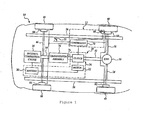
- FIG. 1 is a block diagram of a vehicle incorporating the apparatus of the preferred embodiment of the invention.
- FIG. 1 there is shown a vehicle 10 which includes a regenerative braking confirmation assembly 12 which is made in accordance with the teachings of the preferred embodiment of the invention.
- vehicle 10 includes a torque generator 14, such as but not limited to an internal combustion engine or fuel cell assembly, and a transmission assembly 16 which is physically coupled to the torque generator 14 by a powertrain member 18.
- Vehicle 10 further includes a regenerative brake assembly 20 which comprises a motor 22, a clutch 24, and a battery 26.
- the clutch 24 is physically coupled to the transmission 16 by the output shaft 76, and to the motor 22.
- the motor 22 is electrically coupled to the battery 26 and the battery 26 may comprise a conventional vehicular battery.
- vehicle 10 includes a differential assembly 30 which is physically coupled to the clutch 24 by a powertrain member 32.
- vehicle 10 includes a pair of rear axles or half shafts 36, 38 which are each coupled to the differential assembly 30 and to a respective rear wheel 40, 42.
- vehicle 10 also includes a front axle 46 which is coupled to a pair of front wheels 48, 50, and frame members 54, 56 which are coupled to the front axle 46.
- Frame member 54 is further coupled to the rear axle 38 while the frame member 56 is coupled to the rear axle 36.
- Vehicle 10 further includes frictional brake assemblies 60, 62, 64, and 66 which respectively reside upon or in close proximity to wheels 40, 42, 48, and 50 and which selectively and frictionally brake these respective wheels 40, 42, 48, and 50, effective to slow or stop the vehicle 10 (e.g., to brake the vehicle 10), and a controller 70 which is operable under stored program control and which is physically and communicatively coupled to the clutch 24 and to the frictional brake assemblies 60-66.
- frictional brake assemblies 60, 62, 64, and 66 which respectively reside upon or in close proximity to wheels 40, 42, 48, and 50 and which selectively and frictionally brake these respective wheels 40, 42, 48, and 50, effective to slow or stop the vehicle 10 (e.g., to brake the vehicle 10)
- a controller 70 which is operable under stored program control and which is physically and communicatively coupled to the clutch 24 and to the frictional brake assemblies 60-66.
- Vehicle 10 also includes a selectively depressible brake request member or brake pedal 73 which is coupled to the controller 70. That is, controller 70, in one embodiment, forms part of the regenerative braking confirmation assembly 12 and also provides other vehicular functions which are set forth below. In other non-limiting embodiment, a separate controller may be used to provide the regenerative braking confirmation function of the preferred embodiment of the invention.
- vehicle 10 discloses a rear wheel drive vehicle
- present invention is applicable to a wide variety of vehicular architectures, including but not limited to a front wheel drive vehicle, an all wheel drive vehicle, and/or an "on demand" drive vehicle and that nothing in this description is meant to limit the applicability of the present invention only to the type of vehicle which is shown in Figure 1.
- torque is produced by the torque generator 14 and is communicated to the transmission 16 by the drivetrain member 18.
- the transmission 16 then outputs at least a portion of the received torque by the use of the output shaft or member 76 which is coupled to the clutch 24 and to the transmission 16.
- the controller 70 controllably causes the clutch 24 to communicate the torque which is output from the transmission 16 (i.e., from the shaft 76) to the differential 30, by the use of powertrain member 32.
- the differential 30 then communicates the torque to the axles 36, 38, effective to allow the wheels 40, 42 to rotate and to allow the vehicle 10 to be driven.
- the controller 70 When the controller 70 senses a depression of the member 73, the controller 70 controllably causes the clutch 24 to communicate the torque emanating from the output member 76 to the motor 22.
- the received torque causes the motor 22 to function as a generator and to communicate the generated electrical energy into the battery 26, thereby conserving energy (e.g., transforming the received kinetic energy into electrical energy) while braking or decelerating the vehicle 10 (e.g., regeneratively braking the vehicle 10).
- the controller 70 activates the frictional braking assemblies 60-66.
- frictional braking assemblies 60-66 may be employed such as those which are hydraulically or pneumatically activated and those which are of the "antilock" type.
- a wide variety of regenerative braking assemblies may be used to replace the assembly 20, including but not limited to those including a flywheel which receives torque from the clutch 24, and that nothing in this description is meant to limit the present invention to use with a certain type of regenerative braking assembly or frictional braking assembly.
- Regenerative braking confirmation assembly 12 includes or makes use of the controller 70.
- one or more controllers may be used to perform the functionality and methodology of the preferred embodiment of the invention. Nothing in this application is meant to limit the use of the present invention to a certain type of controller architecture.
- Assembly 12 further includes at least one speed sensor 80 which is coupled to the controller 70 and which is adapted to sense the speed of the wheel 40 and to communicate the sensed speed to the controller 70. While a single sensor 80 is shown in Figure 1, it should be appreciated that additional numbers of sensors may be employed in other non-limiting embodiments of the invention on any or all of the other wheels 42, 48 and 50.
- controller 70 when controller 70 causes the clutch 24 to regeneratively brake the vehicle 10, the controller 70 communicates with the at least one speed sensor 80 in order to ascertain whether the vehicle 10 is decelerating (i.e., whether the vehicle 10 is being regeneratively braked).
- the controller 70 automatically (i.e., without intervention by the user or operator of the vehicle) causes the frictional braking assemblies 60-66 to decelerate the vehicle 10, and may provide status or other types of information to the user/driver indicating that the desired regenerative braking has not occurred or is not occurring.
- the vehicle deceleration may be calculated by conventional slip control equations which utilize the wheel speed which is provided by the at least one sensor 80. Such a calculation may occur within controller 70. If additional wheel sensors are utilized, these equations are sequentially and separately applied to the respective wheel speed data emanating from these other sensors and the controller 70 only activates the frictional braking assemblies 60-66 if all of the data (for each wheel 40, 42, 48, 50) shows a lack of deceleration.
- discrete positions of the member 73 are calibrated to ascertain the amount of deceleration which is respectively requested by each position.
- This calibrated data (along with the data associated with the current position of the member 73) is stored within the controller 70 and is used, by the controller 70, in combination with the data emanating from the at least one speed sensor 80 to not only ascertain whether the vehicle 10 is being decelerated, but to determine whether the requested amount of deceleration has been achieved.
- the frictional braking is not applied until it is determined that the full amount of the requested regenerative braking has not been applied to the vehicle 10.
- torque generator 14 may comprise a reservoir of fluid in combination with a hydraulic pump which is communicatively coupled to the reservoir and controllably coupled to the controller 70.
- powertrain member 18 may be replaced by at least one hydraulic conduit and transmission 16 may be replaced by an assembly which rotates in response to the receipt of fluid.
- the pump upon receipt of certain signals from the controller 70, the pump in cooperation with the reservoir will selectively couple the fluid to the transmission which causes the transmission to hydraulically provide positive or negative torque to accelerate or decelerate the vehicle 10.
Landscapes
- Engineering & Computer Science (AREA)
- Power Engineering (AREA)
- Transportation (AREA)
- Mechanical Engineering (AREA)
- Physics & Mathematics (AREA)
- Electromagnetism (AREA)
- Electric Propulsion And Braking For Vehicles (AREA)
- Regulating Braking Force (AREA)
Abstract
Description
- The present invention generally relates to a method and an apparatus for determining whether a vehicle has been regeneratively braked and for frictionally braking the vehicle in the event that the vehicle has not been regeneratively braked and to a vehicle which incorporates the method and apparatus.
- A vehicle may be braked or selectively decelerated or slowed by the use of several techniques or strategies. For example, a hybrid type vehicle may be regeneratively braked by selectively coupling the torque emanating from the transmission or powertrain assembly to an energy storage device (e.g., a flywheel assembly), thereby conserving energy while slowing or decelerating the vehicle. Some regenerative strategies require that the torque be converted into electrical energy, by a motor, and then stored within a battery.
- While such regeneration does desirably slow a vehicle's velocity or speed, it does not typically provide sufficient deceleration to actually stop the vehicle. Hence, these regenerative braking strategies must normally be used in combination with traditional braking strategies which require the use of a frictional brake assembly on each of the wheels. Particularly, a frictional brake assembly selectively engages the wheel on which it is operatively disposed and, in this manner, these frictional brake assemblies selectively and cooperatively decelerate and stop a vehicle.
- There exist a number of unique strategies which utilize such frictional braking assemblies and which seek to dynamically distribute the amount of braking between braking assemblies located at the rear of the vehicle (i.e., behind the driver) and the front of the vehicle in order to maintain overall vehicular stability. Typically, the vehicle is initially regeneratively braked in order to maximize the amount of energy which may be regeneratively stored and concomitantly decrease the use of the frictional brakes which wear over time and must be replaced or serviced.
- It is desirable to confirm whether regenerative deceleration of the vehicle has occurred and/or to confirm that the regenerative braking system is operable in order to avoid a relatively sudden application of the frictional brakes which is necessary in order to achieve the desired vehicular braking. Particularly, such a sudden application of the frictional brakes both reduces the operating life of these brakes, provides discomfort and annoyance to the passengers of the vehicle, and oftentimes prevents a desired brake distribution to occur.
- It is an object of the invention to provide an improved method and apparatus for regeneratively braking a motor vehicle.
- According to a first aspect of the invention there is provided an assembly for braking a motor vehicle comprising a selectively operable frictional braking assembly, a sensor to determine whether regenerative braking has been applied to the vehicle and which generates a signal in the absence of the application of said regenerative braking to said vehicle and a controller assembly which is arranged to receive said signal from said sensor and is coupled to said selectively operable frictional braking assembly wherein, in response to said receipt of said signal from said sensor, the controller assembly is operable to selectively activate said frictional braking assembly so as to brake said vehicle.
- Said sensor may comprise a wheel speed sensor.
- Said controller may further determine if a certain amount of regenerative braking has occurred within a certain predetermined amount of time and, in response to a determination that said certain amount of regenerative braking has not occurred within said predetermined amount of time, said controller selectively and automatically activates said frictional braking assembly, effective to brake said vehicle.
- Said assembly may further comprise a selectively movable member which is coupled to said controller and which defines a certain amount of regenerative braking and which communicates said defined and certain amount of regenerative braking to said controller.
- Said selectively movable member may be a brake pedal.
- Said controller may store said defined certain amount of regenerative braking and compares said stored amount of regenerative braking with said signal from said sensor and, based upon said comparison, energizes said frictional braking assembly.
- According to a second aspect of the invention there is provided a motor vehicle having at least one wheel to be selectively braked and an assembly in accordance with said first aspect of the invention.
- The motor vehicle may further comprise a frictional brake assembly which is selectively coupled to said at least one wheel, a regenerative braking assembly; a sensor which measures a speed of said vehicle and which produces a first signal which is indicative of said measured speed; a brake request member which selectively generates a second signal which represents a certain amount of desired vehicular deceleration and a controller which is coupled to said brake request member, to said frictional brake assembly and to said speed sensor, said controller receiving said second signal and, in response to said receipt of said second signal, said controller attempts to decelerate said vehicle by use of said regenerative braking assembly, said controller further receiving said first signal and using said first and second signals to determine whether said vehicle has been decelerated and, based upon said determination, selectively brakes said at least one wheel by use of said frictional brake assembly.
- Said regenerative braking assembly may comprise a motor and a battery.
- Said frictional braking assembly may comprise a wheel braking portion and a pneumatic control which selectively causes said wheel braking portion to selectively decelerate said vehicle.
- Said brake request member may comprise a brake pedal.
- Said sensor may comprise a wheel speed sensor.
- According to a third aspect of the invention there is provided a method for braking a motor vehicle comprising the steps of attempting to regeneratively brake said vehicle, determining whether said vehicle has been regeneratively braked and, if said vehicle has failed to be regeneratively braked, automatically causing said vehicle to be frictionally braked .
- Said step of determining whether said vehicle has been regeneratively braked may comprise the steps of receiving a certain value, creating a second value and comparing said second value to said certain value.
- The second value may be a sensed amount of deceleration of said vehicle. The certain value may be a deceleration value which is dependent upon the position of a brake pedal.
- The method may further comprise the step of providing status information that said vehicle has failed to be regeneratively braked.
- Said vehicle may have at least one of a motor assembly and a flywheel selectively connectable to a transmission arranged to transfer torque and said step of attempting to regeneratively brake said vehicle may comprise the step of coupling one of said motor assembly and said flywheel to said transmission.
- Said vehicle may have at least one wheel and a sensor associated therewith to determine the speed of rotation of the wheel and said step of determining whether said vehicle has been regeneratively braked may comprise the step of continuously monitoring the output from the sensor.
- Said step of determining whether said vehicle has been regeneratively braked may further comprise the step of calculating a certain amount of deceleration of said at least one wheel.
- The invention will now be described by way of example with reference to the accompanying drawing Figure 1 which is a block diagram of a vehicle incorporating the apparatus of the preferred embodiment of the invention.
- Referring now to Figure 1, there is shown a
vehicle 10 which includes a regenerativebraking confirmation assembly 12 which is made in accordance with the teachings of the preferred embodiment of the invention. - Particularly,
vehicle 10 includes atorque generator 14, such as but not limited to an internal combustion engine or fuel cell assembly, and atransmission assembly 16 which is physically coupled to thetorque generator 14 by apowertrain member 18.Vehicle 10 further includes aregenerative brake assembly 20 which comprises a motor 22, aclutch 24, and abattery 26. Particularly, theclutch 24 is physically coupled to thetransmission 16 by theoutput shaft 76, and to the motor 22. The motor 22 is electrically coupled to thebattery 26 and thebattery 26 may comprise a conventional vehicular battery. - Further, the
vehicle 10 includes adifferential assembly 30 which is physically coupled to theclutch 24 by apowertrain member 32. Moreover,vehicle 10 includes a pair of rear axles orhalf shafts differential assembly 30 and to a respectiverear wheel 40, 42. Thevehicle 10 also includes afront axle 46 which is coupled to a pair offront wheels frame members front axle 46.Frame member 54 is further coupled to therear axle 38 while theframe member 56 is coupled to therear axle 36. -
Vehicle 10 further includesfrictional brake assemblies wheels respective wheels controller 70 which is operable under stored program control and which is physically and communicatively coupled to theclutch 24 and to the frictional brake assemblies 60-66. -
Vehicle 10 also includes a selectively depressible brake request member orbrake pedal 73 which is coupled to thecontroller 70. That is,controller 70, in one embodiment, forms part of the regenerativebraking confirmation assembly 12 and also provides other vehicular functions which are set forth below. In other non-limiting embodiment, a separate controller may be used to provide the regenerative braking confirmation function of the preferred embodiment of the invention. - It should be realized that only the relevant portions of
vehicle 10 are shown within Figure 1 and described above and that while thevehicle 10 discloses a rear wheel drive vehicle, the present invention is applicable to a wide variety of vehicular architectures, including but not limited to a front wheel drive vehicle, an all wheel drive vehicle, and/or an "on demand" drive vehicle and that nothing in this description is meant to limit the applicability of the present invention only to the type of vehicle which is shown in Figure 1. - In conventional operation, torque is produced by the
torque generator 14 and is communicated to thetransmission 16 by thedrivetrain member 18. Thetransmission 16 then outputs at least a portion of the received torque by the use of the output shaft ormember 76 which is coupled to theclutch 24 and to thetransmission 16. Typically, thecontroller 70 controllably causes theclutch 24 to communicate the torque which is output from the transmission 16 (i.e., from the shaft 76) to thedifferential 30, by the use ofpowertrain member 32. Thedifferential 30 then communicates the torque to theaxles wheels 40, 42 to rotate and to allow thevehicle 10 to be driven. - When the
controller 70 senses a depression of themember 73, thecontroller 70 controllably causes theclutch 24 to communicate the torque emanating from theoutput member 76 to the motor 22. The received torque causes the motor 22 to function as a generator and to communicate the generated electrical energy into thebattery 26, thereby conserving energy (e.g., transforming the received kinetic energy into electrical energy) while braking or decelerating the vehicle 10 (e.g., regeneratively braking the vehicle 10). When the maximum allowable amount of regenerative braking has been achieved and additional amounts of braking have been requested, thecontroller 70 activates the frictional braking assemblies 60-66. It should be realized that a wide variety of frictional braking assemblies 60-66 may be employed such as those which are hydraulically or pneumatically activated and those which are of the "antilock" type. Moreover, it should be appreciated that a wide variety of regenerative braking assemblies may be used to replace theassembly 20, including but not limited to those including a flywheel which receives torque from theclutch 24, and that nothing in this description is meant to limit the present invention to use with a certain type of regenerative braking assembly or frictional braking assembly. - Regenerative
braking confirmation assembly 12 includes or makes use of thecontroller 70. In other non-limiting embodiments, one or more controllers may be used to perform the functionality and methodology of the preferred embodiment of the invention. Nothing in this application is meant to limit the use of the present invention to a certain type of controller architecture. -
Assembly 12 further includes at least onespeed sensor 80 which is coupled to thecontroller 70 and which is adapted to sense the speed of thewheel 40 and to communicate the sensed speed to thecontroller 70. While asingle sensor 80 is shown in Figure 1, it should be appreciated that additional numbers of sensors may be employed in other non-limiting embodiments of the invention on any or all of theother wheels - Hence, according to the teachings of the preferred embodiment of the invention, when
controller 70 causes theclutch 24 to regeneratively brake thevehicle 10, thecontroller 70 communicates with the at least onespeed sensor 80 in order to ascertain whether thevehicle 10 is decelerating (i.e., whether thevehicle 10 is being regeneratively braked). If, after some predetermined period of time, vehicular deceleration is not sensed (or, in one non-limiting embodiment of the invention, if a certain predetermined amount of vehicular deceleration is not sensed), thecontroller 70 automatically (i.e., without intervention by the user or operator of the vehicle) causes the frictional braking assemblies 60-66 to decelerate thevehicle 10, and may provide status or other types of information to the user/driver indicating that the desired regenerative braking has not occurred or is not occurring. - In one non-limiting embodiment of the invention, the vehicle deceleration may be calculated by conventional slip control equations which utilize the wheel speed which is provided by the at least one
sensor 80. Such a calculation may occur withincontroller 70. If additional wheel sensors are utilized, these equations are sequentially and separately applied to the respective wheel speed data emanating from these other sensors and thecontroller 70 only activates the frictional braking assemblies 60-66 if all of the data (for eachwheel - The use of such slip control equations is explained within the paper entitled Comparison of Control Methods for Electric Vehicle Antilock Braking/Traction Control Systems, which is authored by P. Khatum, C.M. Bimgham, and P.H. Mellor, which is published by the Society of Automotive Engines (2001-01-0596).
- In another non-limiting embodiment, discrete positions of the
member 73 are calibrated to ascertain the amount of deceleration which is respectively requested by each position. This calibrated data (along with the data associated with the current position of the member 73) is stored within thecontroller 70 and is used, by thecontroller 70, in combination with the data emanating from the at least onespeed sensor 80 to not only ascertain whether thevehicle 10 is being decelerated, but to determine whether the requested amount of deceleration has been achieved. In an alternate embodiment of the invention, the frictional braking is not applied until it is determined that the full amount of the requested regenerative braking has not been applied to thevehicle 10. - In an alternate embodiment,
torque generator 14 may comprise a reservoir of fluid in combination with a hydraulic pump which is communicatively coupled to the reservoir and controllably coupled to thecontroller 70. In this alternate embodiment,powertrain member 18 may be replaced by at least one hydraulic conduit andtransmission 16 may be replaced by an assembly which rotates in response to the receipt of fluid. In operation, upon receipt of certain signals from thecontroller 70, the pump in cooperation with the reservoir will selectively couple the fluid to the transmission which causes the transmission to hydraulically provide positive or negative torque to accelerate or decelerate thevehicle 10. - It is to be understood that the invention is not limited to the exact construction and method which has been described above, but that various changes and modifications may be made without departing from the scope of the inventions.
Claims (10)
- An assembly for braking a motor vehicle (10) characterised in that the assembly comprises a selectively operable frictional braking assembly (60, 62, 64, 66), a sensor (80) to determine whether regenerative braking has been applied to the vehicle (10) and which generates a signal in the absence of the application of said regenerative braking to said vehicle (10) and a controller assembly (70) which is arranged to receive said signal from said sensor (80) and is coupled to said selectively operable frictional braking assembly (60, 62, 64, 66) wherein, in response to said receipt of said signal from said sensor (80), the controller assembly (70) is operable to selectively activate said frictional braking assembly (60, 62, 64, 66) so as to brake said vehicle (10).
- An assembly as claimed in Claim 1 wherein said sensor comprises a wheel speed sensor (80).
- An assembly as claimed in Claim 1 or in claim 2 wherein said controller (70) further determines if a certain amount of regenerative braking has occurred within a certain predetermined amount of time and, in response to a determination that said certain amount of regenerative braking has not occurred within said predetermined amount of time, said controller (70) selectively and automatically activates said frictional braking assembly (60, 62, 64, 66), effective to brake said vehicle (10).
- An assembly as claimed in any of Claims 1 to 3 wherein said assembly further comprises a selectively movable member (73) which is coupled to said controller (70) and which defines a certain amount of regenerative braking and which communicates said defined and certain amount of regenerative braking to said controller (70).
- An assembly as claimed in Claim 4 wherein said controller (70) stores said defined certain amount of regenerative braking and compares said stored amount of regenerative braking with said signal from said sensor (80) and, based upon said comparison, energizes said frictional braking assembly (60, 62, 64, 66).
- A motor vehicle (10) having at least one wheel (40, 42, 48, 50) to be selectively braked characterised in that the motor vehicle includes an assembly as claimed in any of claims 1 to 5.
- A method for braking a motor vehicle (10) characterised in that the method comprises the steps of attempting to regeneratively brake said vehicle (10), determining whether said vehicle (10) has been regeneratively braked and, if said vehicle (10) has failed to be regeneratively braked, automatically causing said vehicle to be frictionally braked.
- A method as claimed in Claim 7 wherein said step of determining whether said vehicle (10) has been regeneratively braked comprises the steps of receiving a certain value, creating a second value and comparing said second value to said certain value.
- A method as claimed in claim 7 or in claim 8 wherein the method further comprises the step of providing status information that said vehicle (10) has failed to be regeneratively braked.
- A method as claimed in any of claims 7 to 9 wherein said vehicle (10) has at least one wheel (40, 42, 48, 50) and a sensor (80) associated therewith to determine the speed of rotation of the wheel (40, 42, 48, 50) and said step of determining whether said vehicle (10) has been regeneratively braked comprises the step of continuously monitoring the output from the sensor (80).
Applications Claiming Priority (2)
| Application Number | Priority Date | Filing Date | Title |
|---|---|---|---|
| US63193 | 2002-03-28 | ||
| US10/063,193 US20030184153A1 (en) | 2002-03-28 | 2002-03-28 | Method and apparatus for vehicle regenerative braking |
Publications (2)
| Publication Number | Publication Date |
|---|---|
| EP1348592A1 true EP1348592A1 (en) | 2003-10-01 |
| EP1348592B1 EP1348592B1 (en) | 2005-07-06 |
Family
ID=27803625
Family Applications (1)
| Application Number | Title | Priority Date | Filing Date |
|---|---|---|---|
| EP03100112A Expired - Lifetime EP1348592B1 (en) | 2002-03-28 | 2003-01-21 | A method and apparatus for vehicle regenerative braking |
Country Status (4)
| Country | Link |
|---|---|
| US (2) | US20030184153A1 (en) |
| EP (1) | EP1348592B1 (en) |
| JP (1) | JP2003327103A (en) |
| DE (1) | DE60300953T2 (en) |
Families Citing this family (18)
| Publication number | Priority date | Publication date | Assignee | Title |
|---|---|---|---|---|
| US7311163B2 (en) | 2004-11-16 | 2007-12-25 | Eaton Corporation | Regeneration and brake management system |
| JP2011024353A (en) * | 2009-07-16 | 2011-02-03 | Aisin Aw Co Ltd | Guidance device, guidance method, and guidance program |
| US8078353B2 (en) * | 2009-09-11 | 2011-12-13 | Freescale Semiconductor, Inc. | Self monitoring braking system for vehicles |
| US9260087B2 (en) * | 2010-09-29 | 2016-02-16 | GM Global Technology Operations LLC | Regenerative braking system and method for controlling a regenerative braking system |
| US9020669B2 (en) * | 2010-12-29 | 2015-04-28 | Cummins Inc. | Hybrid vehicle driver coach |
| US8688302B2 (en) | 2010-12-31 | 2014-04-01 | Cummins Inc. | Hybrid power system braking control |
| US20120175200A1 (en) * | 2011-01-10 | 2012-07-12 | Ford Global Technologies, Llc | Customized Vehicle Deceleration |
| US8587424B2 (en) * | 2011-12-05 | 2013-11-19 | David Aberizk | Vehicle regenerative deceleration actuator and indicator system and method |
| US20130162009A1 (en) * | 2011-12-22 | 2013-06-27 | Coda Automotive, Inc. | Electric vehicle regenerative braking system |
| WO2014167643A1 (en) * | 2013-04-09 | 2014-10-16 | トヨタ自動車株式会社 | Vehicle brake control device |
| US9677529B2 (en) * | 2013-12-25 | 2017-06-13 | Denso Corporation | Vehicle diagnosis system and method |
| KR101704176B1 (en) * | 2015-03-23 | 2017-02-07 | 현대자동차주식회사 | Brake control method for hybrid electric vehicle |
| US10328802B2 (en) * | 2016-11-11 | 2019-06-25 | Toyota Motor Engineering & Manufacturing North America, Inc. | Systems and methods for adaptive braking using brake wear data |
| CN106740140A (en) * | 2016-11-12 | 2017-05-31 | 深圳市沃特玛电池有限公司 | Feed system and feed method |
| US20180154777A1 (en) * | 2016-12-02 | 2018-06-07 | Faraday&Future Inc. | Braking torque blending system and method for automatic emergency braking |
| KR102341231B1 (en) * | 2017-05-16 | 2021-12-20 | 주식회사 만도 | An actuation unit for braking system |
| JP7218503B2 (en) * | 2018-03-30 | 2023-02-07 | 株式会社アドヴィックス | Vehicle braking control device |
| US20220194232A1 (en) * | 2019-05-06 | 2022-06-23 | Aikar Technology Inc. | A vehicle braking method and system |
Citations (3)
| Publication number | Priority date | Publication date | Assignee | Title |
|---|---|---|---|---|
| US5378053A (en) * | 1993-12-07 | 1995-01-03 | Alliedsignal Inc. | Maximized regenerative braking vehicle braking controller |
| US5399000A (en) * | 1991-12-05 | 1995-03-21 | Honda Giken Kogyo Kabushiki Kaisha | Brake system in electric vehicle |
| US20020030408A1 (en) * | 2000-09-14 | 2002-03-14 | Toyota Jidosha Kabushiki Kaisha | Braking force control apparatus and method of motor vehicle |
Family Cites Families (16)
| Publication number | Priority date | Publication date | Assignee | Title |
|---|---|---|---|---|
| IE45011B1 (en) * | 1976-11-26 | 1982-06-02 | Pcb Controls Ltd | Anti-skid control method and system for a brake equipped vehicle wheel |
| JP3202032B2 (en) * | 1991-06-03 | 2001-08-27 | 本田技研工業株式会社 | Brake control device for electric vehicles |
| DE4212337A1 (en) * | 1992-04-13 | 1993-10-14 | Bosch Gmbh Robert | Safety system for car - has ABS and retardation systems working with common control unit processing sensor signals in parallel channels |
| JP3348954B2 (en) * | 1994-02-09 | 2002-11-20 | 株式会社日本自動車部品総合研究所 | Electric vehicle braking force control device |
| JP3089958B2 (en) * | 1994-12-06 | 2000-09-18 | 三菱自動車工業株式会社 | Electric vehicle braking control device |
| US5615933A (en) * | 1995-05-31 | 1997-04-01 | General Motors Corporation | Electric vehicle with regenerative and anti-lock braking |
| US5511859A (en) * | 1995-08-25 | 1996-04-30 | General Motors Corporation | Regenerative and friction brake blend control |
| DE19604134B4 (en) * | 1996-02-06 | 2004-11-11 | Robert Bosch Gmbh | Method and device for controlling the brake system of motor vehicles with an electric drive |
| US5669679A (en) * | 1996-03-04 | 1997-09-23 | General Motors Corporation | Brake system control |
| JPH11170991A (en) * | 1997-12-16 | 1999-06-29 | Toyota Motor Corp | Electric brake abnormality judging method |
| US6176556B1 (en) * | 1998-09-02 | 2001-01-23 | Chrysler Corporation | Braking system for accommodation of regenerative braking in an electric or hybrid electric vehicle |
| US6186253B1 (en) * | 1998-09-23 | 2001-02-13 | Navistar International Transportation Corp. | Brake activated torque disable in hybrid electric vehicles |
| JP3811372B2 (en) * | 2001-05-30 | 2006-08-16 | トヨタ自動車株式会社 | Braking force control device for vehicle |
| JP4058932B2 (en) * | 2001-10-25 | 2008-03-12 | トヨタ自動車株式会社 | Brake control device for vehicle |
| US6655754B2 (en) * | 2002-04-02 | 2003-12-02 | Ford Global Technologies, Llc | Vehicle brake system having adaptive torque control |
| US6663197B2 (en) * | 2002-04-02 | 2003-12-16 | Ford Global Technologies, Llc | Vehicle brake system having adaptive torque control |
-
2002
- 2002-03-28 US US10/063,193 patent/US20030184153A1/en not_active Abandoned
-
2003
- 2003-01-21 EP EP03100112A patent/EP1348592B1/en not_active Expired - Lifetime
- 2003-01-21 DE DE60300953T patent/DE60300953T2/en not_active Expired - Lifetime
- 2003-03-25 JP JP2003083284A patent/JP2003327103A/en active Pending
-
2004
- 2004-03-29 US US10/708,854 patent/US8251463B2/en not_active Expired - Fee Related
Patent Citations (3)
| Publication number | Priority date | Publication date | Assignee | Title |
|---|---|---|---|---|
| US5399000A (en) * | 1991-12-05 | 1995-03-21 | Honda Giken Kogyo Kabushiki Kaisha | Brake system in electric vehicle |
| US5378053A (en) * | 1993-12-07 | 1995-01-03 | Alliedsignal Inc. | Maximized regenerative braking vehicle braking controller |
| US20020030408A1 (en) * | 2000-09-14 | 2002-03-14 | Toyota Jidosha Kabushiki Kaisha | Braking force control apparatus and method of motor vehicle |
Also Published As
| Publication number | Publication date |
|---|---|
| JP2003327103A (en) | 2003-11-19 |
| US8251463B2 (en) | 2012-08-28 |
| US20040164612A1 (en) | 2004-08-26 |
| EP1348592B1 (en) | 2005-07-06 |
| DE60300953D1 (en) | 2005-08-11 |
| US20030184153A1 (en) | 2003-10-02 |
| DE60300953T2 (en) | 2006-05-11 |
Similar Documents
| Publication | Publication Date | Title |
|---|---|---|
| EP1348592B1 (en) | A method and apparatus for vehicle regenerative braking | |
| US7647997B2 (en) | Regeneration and brake management system | |
| EP3575130B1 (en) | Vehicle control system and method of controlling the same, and braking device | |
| US5615933A (en) | Electric vehicle with regenerative and anti-lock braking | |
| EP0983894B1 (en) | Vehicle speed control using engine and brake systems to achieve target acceleration | |
| US6719379B2 (en) | Method and an apparatus for braking a vehicle | |
| US8380419B2 (en) | Resume speed adaptation for automatic vehicle acceleration at a rate derived from a measured acceleration rate | |
| CN102219018B (en) | The system of propulsive effort is distributed in vehicle | |
| US6406105B1 (en) | Brake system of hybrid type vehicle having front and rear regeneration brakes of different efficiencies | |
| US8924120B2 (en) | Regenerative brake control system and method | |
| US20130162009A1 (en) | Electric vehicle regenerative braking system | |
| US6283239B1 (en) | Auxiliary brake apparatus of hybrid automobile | |
| CN102442310A (en) | Method and driveline stability control system for a vehicle | |
| CN108473139B (en) | Method for determining a measure of brake system usage during vehicle operation | |
| SE1150679A1 (en) | Method and apparatus for determining energy consumption in vehicles | |
| CN114274790A (en) | Power distribution method and system of pure electric vehicle, readable storage medium and vehicle | |
| JP2021130367A (en) | Braking control device of vehicle | |
| EP1688329B1 (en) | Method, device and use of deceleration control of a vehicle | |
| KR20050118926A (en) | Regeneration brake torque map controlling method of 4wd hybrid electric vehicle | |
| US20240190255A1 (en) | Vehicle and method of controllling the same |
Legal Events
| Date | Code | Title | Description |
|---|---|---|---|
| PUAI | Public reference made under article 153(3) epc to a published international application that has entered the european phase |
Free format text: ORIGINAL CODE: 0009012 |
|
| AK | Designated contracting states |
Kind code of ref document: A1 Designated state(s): AT BE BG CH CY CZ DE DK EE ES FI FR GB GR HU IE IT LI LU MC NL PT SE SI SK TR |
|
| AX | Request for extension of the european patent |
Extension state: AL LT LV MK RO |
|
| 17P | Request for examination filed |
Effective date: 20040312 |
|
| AKX | Designation fees paid |
Designated state(s): DE FR GB |
|
| 17Q | First examination report despatched |
Effective date: 20040521 |
|
| GRAP | Despatch of communication of intention to grant a patent |
Free format text: ORIGINAL CODE: EPIDOSNIGR1 |
|
| GRAS | Grant fee paid |
Free format text: ORIGINAL CODE: EPIDOSNIGR3 |
|
| GRAA | (expected) grant |
Free format text: ORIGINAL CODE: 0009210 |
|
| AK | Designated contracting states |
Kind code of ref document: B1 Designated state(s): DE FR GB |
|
| REG | Reference to a national code |
Ref country code: GB Ref legal event code: FG4D |
|
| REF | Corresponds to: |
Ref document number: 60300953 Country of ref document: DE Date of ref document: 20050811 Kind code of ref document: P |
|
| PLBE | No opposition filed within time limit |
Free format text: ORIGINAL CODE: 0009261 |
|
| STAA | Information on the status of an ep patent application or granted ep patent |
Free format text: STATUS: NO OPPOSITION FILED WITHIN TIME LIMIT |
|
| 26N | No opposition filed |
Effective date: 20060407 |
|
| EN | Fr: translation not filed | ||
| PG25 | Lapsed in a contracting state [announced via postgrant information from national office to epo] |
Ref country code: FR Free format text: LAPSE BECAUSE OF FAILURE TO SUBMIT A TRANSLATION OF THE DESCRIPTION OR TO PAY THE FEE WITHIN THE PRESCRIBED TIME-LIMIT Effective date: 20060901 |
|
| PG25 | Lapsed in a contracting state [announced via postgrant information from national office to epo] |
Ref country code: FR Free format text: LAPSE BECAUSE OF FAILURE TO SUBMIT A TRANSLATION OF THE DESCRIPTION OR TO PAY THE FEE WITHIN THE PRESCRIBED TIME-LIMIT Effective date: 20050706 |
|
| REG | Reference to a national code |
Ref country code: DE Ref legal event code: R082 Ref document number: 60300953 Country of ref document: DE Representative=s name: DOERFLER, THOMAS, DR.-ING., DE |
|
| PGFP | Annual fee paid to national office [announced via postgrant information from national office to epo] |
Ref country code: GB Payment date: 20191231 Year of fee payment: 18 |
|
| PGFP | Annual fee paid to national office [announced via postgrant information from national office to epo] |
Ref country code: DE Payment date: 20201218 Year of fee payment: 19 |
|
| GBPC | Gb: european patent ceased through non-payment of renewal fee |
Effective date: 20210121 |
|
| PG25 | Lapsed in a contracting state [announced via postgrant information from national office to epo] |
Ref country code: GB Free format text: LAPSE BECAUSE OF NON-PAYMENT OF DUE FEES Effective date: 20210121 |
|
| REG | Reference to a national code |
Ref country code: DE Ref legal event code: R119 Ref document number: 60300953 Country of ref document: DE |
|
| PG25 | Lapsed in a contracting state [announced via postgrant information from national office to epo] |
Ref country code: DE Free format text: LAPSE BECAUSE OF NON-PAYMENT OF DUE FEES Effective date: 20220802 |