EP1348223B1 - Combination of sheets and method for forming an energy storage device - Google Patents
Combination of sheets and method for forming an energy storage device Download PDFInfo
- Publication number
- EP1348223B1 EP1348223B1 EP01999948A EP01999948A EP1348223B1 EP 1348223 B1 EP1348223 B1 EP 1348223B1 EP 01999948 A EP01999948 A EP 01999948A EP 01999948 A EP01999948 A EP 01999948A EP 1348223 B1 EP1348223 B1 EP 1348223B1
- Authority
- EP
- European Patent Office
- Prior art keywords
- sheets
- sheet
- slots
- transverse
- plates
- Prior art date
- Legal status (The legal status is an assumption and is not a legal conclusion. Google has not performed a legal analysis and makes no representation as to the accuracy of the status listed.)
- Expired - Lifetime
Links
Images












Classifications
-
- H—ELECTRICITY
- H01—ELECTRIC ELEMENTS
- H01G—CAPACITORS; CAPACITORS, RECTIFIERS, DETECTORS, SWITCHING DEVICES, LIGHT-SENSITIVE OR TEMPERATURE-SENSITIVE DEVICES OF THE ELECTROLYTIC TYPE
- H01G11/00—Hybrid capacitors, i.e. capacitors having different positive and negative electrodes; Electric double-layer [EDL] capacitors; Processes for the manufacture thereof or of parts thereof
- H01G11/10—Multiple hybrid or EDL capacitors, e.g. arrays or modules
- H01G11/12—Stacked hybrid or EDL capacitors
-
- H—ELECTRICITY
- H01—ELECTRIC ELEMENTS
- H01G—CAPACITORS; CAPACITORS, RECTIFIERS, DETECTORS, SWITCHING DEVICES, LIGHT-SENSITIVE OR TEMPERATURE-SENSITIVE DEVICES OF THE ELECTROLYTIC TYPE
- H01G11/00—Hybrid capacitors, i.e. capacitors having different positive and negative electrodes; Electric double-layer [EDL] capacitors; Processes for the manufacture thereof or of parts thereof
- H01G11/52—Separators
-
- H—ELECTRICITY
- H01—ELECTRIC ELEMENTS
- H01G—CAPACITORS; CAPACITORS, RECTIFIERS, DETECTORS, SWITCHING DEVICES, LIGHT-SENSITIVE OR TEMPERATURE-SENSITIVE DEVICES OF THE ELECTROLYTIC TYPE
- H01G11/00—Hybrid capacitors, i.e. capacitors having different positive and negative electrodes; Electric double-layer [EDL] capacitors; Processes for the manufacture thereof or of parts thereof
- H01G11/74—Terminals, e.g. extensions of current collectors
-
- H—ELECTRICITY
- H01—ELECTRIC ELEMENTS
- H01G—CAPACITORS; CAPACITORS, RECTIFIERS, DETECTORS, SWITCHING DEVICES, LIGHT-SENSITIVE OR TEMPERATURE-SENSITIVE DEVICES OF THE ELECTROLYTIC TYPE
- H01G11/00—Hybrid capacitors, i.e. capacitors having different positive and negative electrodes; Electric double-layer [EDL] capacitors; Processes for the manufacture thereof or of parts thereof
- H01G11/78—Cases; Housings; Encapsulations; Mountings
- H01G11/82—Fixing or assembling a capacitive element in a housing, e.g. mounting electrodes, current collectors or terminals in containers or encapsulations
-
- H—ELECTRICITY
- H01—ELECTRIC ELEMENTS
- H01G—CAPACITORS; CAPACITORS, RECTIFIERS, DETECTORS, SWITCHING DEVICES, LIGHT-SENSITIVE OR TEMPERATURE-SENSITIVE DEVICES OF THE ELECTROLYTIC TYPE
- H01G2/00—Details of capacitors not covered by a single one of groups H01G4/00-H01G11/00
- H01G2/02—Mountings
- H01G2/06—Mountings specially adapted for mounting on a printed-circuit support
-
- H—ELECTRICITY
- H01—ELECTRIC ELEMENTS
- H01G—CAPACITORS; CAPACITORS, RECTIFIERS, DETECTORS, SWITCHING DEVICES, LIGHT-SENSITIVE OR TEMPERATURE-SENSITIVE DEVICES OF THE ELECTROLYTIC TYPE
- H01G9/00—Electrolytic capacitors, rectifiers, detectors, switching devices, light-sensitive or temperature-sensitive devices; Processes of their manufacture
- H01G9/004—Details
- H01G9/08—Housing; Encapsulation
- H01G9/10—Sealing, e.g. of lead-in wires
-
- H—ELECTRICITY
- H01—ELECTRIC ELEMENTS
- H01M—PROCESSES OR MEANS, e.g. BATTERIES, FOR THE DIRECT CONVERSION OF CHEMICAL ENERGY INTO ELECTRICAL ENERGY
- H01M10/00—Secondary cells; Manufacture thereof
- H01M10/04—Construction or manufacture in general
- H01M10/0436—Small-sized flat cells or batteries for portable equipment
-
- H—ELECTRICITY
- H01—ELECTRIC ELEMENTS
- H01G—CAPACITORS; CAPACITORS, RECTIFIERS, DETECTORS, SWITCHING DEVICES, LIGHT-SENSITIVE OR TEMPERATURE-SENSITIVE DEVICES OF THE ELECTROLYTIC TYPE
- H01G11/00—Hybrid capacitors, i.e. capacitors having different positive and negative electrodes; Electric double-layer [EDL] capacitors; Processes for the manufacture thereof or of parts thereof
- H01G11/74—Terminals, e.g. extensions of current collectors
- H01G11/76—Terminals, e.g. extensions of current collectors specially adapted for integration in multiple or stacked hybrid or EDL capacitors
-
- H—ELECTRICITY
- H01—ELECTRIC ELEMENTS
- H01M—PROCESSES OR MEANS, e.g. BATTERIES, FOR THE DIRECT CONVERSION OF CHEMICAL ENERGY INTO ELECTRICAL ENERGY
- H01M6/00—Primary cells; Manufacture thereof
- H01M6/04—Cells with aqueous electrolyte
- H01M6/06—Dry cells, i.e. cells wherein the electrolyte is rendered non-fluid
- H01M6/10—Dry cells, i.e. cells wherein the electrolyte is rendered non-fluid with wound or folded electrodes
-
- H—ELECTRICITY
- H01—ELECTRIC ELEMENTS
- H01M—PROCESSES OR MEANS, e.g. BATTERIES, FOR THE DIRECT CONVERSION OF CHEMICAL ENERGY INTO ELECTRICAL ENERGY
- H01M6/00—Primary cells; Manufacture thereof
- H01M6/42—Grouping of primary cells into batteries
-
- Y—GENERAL TAGGING OF NEW TECHNOLOGICAL DEVELOPMENTS; GENERAL TAGGING OF CROSS-SECTIONAL TECHNOLOGIES SPANNING OVER SEVERAL SECTIONS OF THE IPC; TECHNICAL SUBJECTS COVERED BY FORMER USPC CROSS-REFERENCE ART COLLECTIONS [XRACs] AND DIGESTS
- Y02—TECHNOLOGIES OR APPLICATIONS FOR MITIGATION OR ADAPTATION AGAINST CLIMATE CHANGE
- Y02E—REDUCTION OF GREENHOUSE GAS [GHG] EMISSIONS, RELATED TO ENERGY GENERATION, TRANSMISSION OR DISTRIBUTION
- Y02E60/00—Enabling technologies; Technologies with a potential or indirect contribution to GHG emissions mitigation
- Y02E60/10—Energy storage using batteries
-
- Y—GENERAL TAGGING OF NEW TECHNOLOGICAL DEVELOPMENTS; GENERAL TAGGING OF CROSS-SECTIONAL TECHNOLOGIES SPANNING OVER SEVERAL SECTIONS OF THE IPC; TECHNICAL SUBJECTS COVERED BY FORMER USPC CROSS-REFERENCE ART COLLECTIONS [XRACs] AND DIGESTS
- Y02—TECHNOLOGIES OR APPLICATIONS FOR MITIGATION OR ADAPTATION AGAINST CLIMATE CHANGE
- Y02E—REDUCTION OF GREENHOUSE GAS [GHG] EMISSIONS, RELATED TO ENERGY GENERATION, TRANSMISSION OR DISTRIBUTION
- Y02E60/00—Enabling technologies; Technologies with a potential or indirect contribution to GHG emissions mitigation
- Y02E60/13—Energy storage using capacitors
-
- Y—GENERAL TAGGING OF NEW TECHNOLOGICAL DEVELOPMENTS; GENERAL TAGGING OF CROSS-SECTIONAL TECHNOLOGIES SPANNING OVER SEVERAL SECTIONS OF THE IPC; TECHNICAL SUBJECTS COVERED BY FORMER USPC CROSS-REFERENCE ART COLLECTIONS [XRACs] AND DIGESTS
- Y02—TECHNOLOGIES OR APPLICATIONS FOR MITIGATION OR ADAPTATION AGAINST CLIMATE CHANGE
- Y02P—CLIMATE CHANGE MITIGATION TECHNOLOGIES IN THE PRODUCTION OR PROCESSING OF GOODS
- Y02P70/00—Climate change mitigation technologies in the production process for final industrial or consumer products
- Y02P70/50—Manufacturing or production processes characterised by the final manufactured product
Definitions
- FIG. 1 there is illustrated a surface mount energy storage device in the form of a supercapacitor 1.
- the supercapacitor includes a generally rectangular folded prismatic housing 2 and two energy storage elements (not shown) that are sealingly contained within the housing and which are connected in series.
- a mount in the form of an integrally formed tinned metal frame 3, extends about and captively retains housing 2 in the folded configuration shown.
- Two terminals, in the form of elongate contacts 4 and 5 extend from the energy storage elements and terminate outside housing 2 for allowing external electrical connection to the elements.
- Frame 3 includes two like and parallel elongate planar side members 7 and 8 that are interlinked by two spaced apart transverse members 9 and 10.
- Frame 3 also includes four spaced apart feet 11 that extend outwardly from members 7 and 8 for defining substantially planar contacts that are abutted and soldered to a PCB.
- Other forms of attachments will be understood by those skilled in the art to be equally applicable.
- Frame 3 is punched from a single metal blank that is deformed into the desired configuration. That is, all members, tabs and feet are integrally formed. In other embodiments frame 3 is constructed from other metals and it is also envisaged that other materials such as plastics are suitable. In the latter case it is necessary to glue or otherwise adhere the plastics tabs to the frame. Alternatively, moveable plastics tabs are possible, although at the cost of complexity.
- Sheet 15 is continuous and includes two longitudinally extending edges 16 and 17 that are transversely spaced apart by 31.5 mm.
- Sheet 15 also includes a centrally applied continuous carbon coating 18 that has two transverse edges 19 and 20 that are spaced apart by 15.5 mm.
- the carbon coating is used to provide a high surface area for the electrode.
- the coating in this embodiment includes:
- edge 16 remains untrimmed so that sheet 15 defines a common conductive tab 21 that lies between edges 16 and 19.
- This tab is about 8 mm wide and its function will be described in more detail below.
- the cutting of the sheets provides a plurality of electrode units having a cross section the same as that shown in Figure 8 and a length equal to the distance between the centres of adjacent slots 22. These plurality of electrode units are stacked back-to-back so that the back of sheet 57 and 58 of one electrode unit are aligned and abutted with the back of a respective sheet 58 and 57 of another electrode unit.
- the number of units in the stack is dependent upon the capacitance that supercapacitor 1 is designed to provide. The greater the capacitance desired, the more units that will be required.
- the layered combination of sheets that leaves station 56 is not cut but, rather, rolled in a flat stack that has an initial width which is the distance between adj acent slots 22.
- the sheets take the form illustrated in Figure 12 . That is, the rolling occurs along a transverse axis and tabs 21 and 63 protrude from opposite transverse ends of the roll.
- the sheets are retained in the rolled configuration by the application of an ultrasonic weld 66 to the roll. While this embodiment is concerned with the rolling of four coated aluminium sheets, in other embodiments more sheets, and the required separator sheets, are used.
- Figure 9 is a cross sectional view similar to that of Figure 8 where corresponding features are denoted by corresponding reference numerals.
- this folded sheet includes two separate carbon strips, one each side of the fold.
- the sheet includes a single carbon strip that is centrally folded upon folding of the sheet as a whole.
- Package 92 is also folded along fold lines 96.
- the folded portions overlap with the cell and are folded onto the same side of the cell as the other folded portions. In this embodiment all the folded portions do not overlap each other, although in other embodiments this does occur.
- This configuration allows the heating and sealing operation to occur across a large continuous area 81, as shown in Figure 24 . That is, only a single area has heat and pressure applied to it, as opposed to the three separate areas 81, 82 and 83 of the Figure 17 embodiment.
Landscapes
- Engineering & Computer Science (AREA)
- Power Engineering (AREA)
- Microelectronics & Electronic Packaging (AREA)
- Manufacturing & Machinery (AREA)
- Chemical & Material Sciences (AREA)
- Chemical Kinetics & Catalysis (AREA)
- Electrochemistry (AREA)
- General Chemical & Material Sciences (AREA)
- Electric Double-Layer Capacitors Or The Like (AREA)
- Battery Mounting, Suspending (AREA)
- Gas-Filled Discharge Tubes (AREA)
- Separation By Low-Temperature Treatments (AREA)
Description
- The present invention relates to a combination of sheets and a method for forming an energy storage device.
- The invention has been developed primarily for supercapacitors and will be described hereinafter with reference to that application. However, it will be appreciated that the invention is not limited to this particular field of use and is also applicable to other energy storage devices such as batteries, capacitors, fuel cells and the like.
- Hitherto, a variety of capacitors and supercapacitors and other energy storage devices have been devised. However, particularly for supercapacitors, the technology has not been well understood and development has been hindered through the need to use:
- 1. Electrolytes that are volatile, corrosive and easily contaminable;
- 2. Expensive and labour intensive manufacturing techniques that add significantly to the unit cost of the supercapacitors;
- 3. Expensive materials and handling procedures that also add significantly to the unit cost of the supercapacitors;
- 4. Rigid packaging;
- 5. Bulky packaging; and
- 6. Packaging that is extremely susceptible to leakage.
- All these factors generally contribute to wide performance variations between devices that are made with the same process. Moreover, the cost of the resultant supercapacitors limits the range of products to which they can be commercially applied.
-
JP 10 070052 -
JP 2130907 A -
GB 2270720 A - Any discussion of the prior art throughout the specification should in no way be considered as an admission that such prior art is widely known or forms part of common general knowledge in the field.
- It is an object of the present invention, at least in the preferred embodiments, to overcome or substantially ameliorate one or more of the disadvantages of the prior art.
- According to a first aspect of the invention there is provided a combination of sheets according to
claim 1. - According to a second aspect of the invention there is provided a method according to
claim 2 for forming an energy storage device from a continuous longitudinally extending conductive sheet of a predetermined transverse width. - Preferably, the sheet includes two opposite transverse edges that are spaced apart by the predetermined width and the method includes the step forming the slots such that they extend from one of the transverse edges and terminate adjacent to the other edge.
- The method includes the step of joining the two opposed separator sheets with each other through the slots. The joining of the separator sheets is by way of bonding.
- In some embodiments the bonding is by way of heat sealing. In other embodiments the bonding is by way of heat welding. More preferably, the heat sealing or welding extends longitudinally across substantially all the slot. Even more preferably, the heat sealing or welding extends transversely across substantially all the slot.
- In other embodiments the heat sealing is affected at two or more spaced apart locations in the slot.
- In a preferred form the method includes the step of alternately stacking the first and the second plurality of plates with each other. More preferably, the method includes the step of stacking the first and the second plurality of plates with each other in a single stack.
- In a preferred form, the method includes the step of applying a coating to the sheet, wherein the coating includes activated carbon particles and a binder.
- Preferred embodiments of the invention will now be described, by way of example only, with reference to the accompanying drawings. All the drawings are schematic and none are to scale. Particularly:
-
Figure 1 is a top perspective view of a supercapacitor -
Figure 1 a is an enlarged front view of an alternative contact for the supercapacitor ofFigure 1 ; -
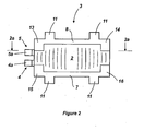
Figure 2 is an underside view of a supercapacitor ofFigure 1 ; -
Figure 2a is a cross sectional view of the supercapacitor ofFigure 2 taken alongline 2a-2a; -
Figure 3 is a plan view of a carbon coated aluminium sheet that is used to produce an electrode for the supercapacitor ofFigure 1 ; -
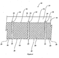
Figure 4 is a plan view of the sheet ofFigure 3 with a plurality of slots; -
Figure 5 is a perspective view of some steps in a manufacturing process according to the invention; -
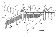
Figure 6 is a plan view of some additional steps following the steps ofFigure 5 ; -
Figure 7 is a perspective view of some process steps following the steps ofFigure 6 ; -
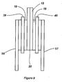
Figure 8 is a cross section taken along line 8-8 ofFigure 7 ; -
Figure 9 is a cross section similar to that ofFigure 8 illustrating an alternative embodiment of the invention; -
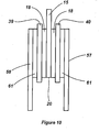
Figure 10 is a cross section similar to that ofFigure 8 illustrating a further embodiment of the invention; -
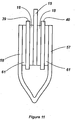
Figure 11 is a cross section similar to that ofFigure 8 illustrating a further alternative embodiment of the invention; -
Figure 11a is a cross section similar to that ofFigure 8 illustrating a further alternative embodiment of the invention; -
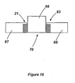
Figure 12 is a perspective view of a rolled combination of sheets; -
Figure 13 is a perspective view of a cut and stacked combination of sheets; -
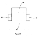
Figure 14 is a plan view of a capacitive cell with its tabs trimmed; -
Figure 14a is a plan view of an alternative capacitive cell with its tabs trimmed; -
Figure 14b is a plan view of a further alternative capacitive cell with its tabs trimmed; -
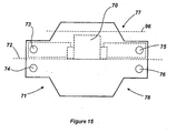
Figure 15 is a plan view of the capacitive cell ofFigure 14 lying on the sheet that is to be formed into a housing; -
Figure 15a is an underside view of the housing ofFigure 15 ; -
Figure 15b is a view similar to that ofFigure 15 , illustrating an alternative sheet; -
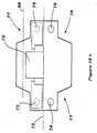
Figure 16 is a plan view of a capacitive cell and terminals; -
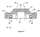
Figure 17 is a plan view of the cell ofFigure 14 in a folded enclosure; -
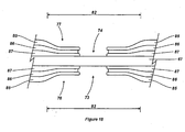
Figure 18 is a sectional view taken along line 18-18 ofFigure 17 ; -
Figure 19 is a perspective view of two cells being arranged for connection together; -
Figure 20 is a perspective view of the cell ofFigure 19 in a partially folded configuration; -
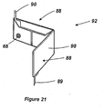
Figure 21 is a perspective view of the cell ofFigure 20 being further folded; -
Figure 22 is view similar to that ofFigure 15 of an alternative embodiment of the invention; -
Figure 23 is a view similar to that ofFigure 15a for the embodiment ofFigure 22 ; -
Figure 24 is a view similar to that ofFigure 17 for the embodiment ofFigure 22 ;
and -
Figure 25 is a view similar to that ofFigure 19 for the embodiment ofFigure 22 . - Referring to
Figure 1 there is illustrated a surface mount energy storage device in the form of asupercapacitor 1. The supercapacitor includes a generally rectangular foldedprismatic housing 2 and two energy storage elements (not shown) that are sealingly contained within the housing and which are connected in series. A mount, in the form of an integrally formedtinned metal frame 3, extends about and captively retainshousing 2 in the folded configuration shown. Two terminals, in the form ofelongate contacts outside housing 2 for allowing external electrical connection to the elements. - In this
example contacts planar ends Figure 1a , the contacts extend downwardly and through corresponding located apertures in the PCB. In this case, the ends, as illustrated by the end numbered 4b, are soldered to the side of the PCB that is opposite tosupercapacitor 1. In still further examples theends -
Frame 3 includes two like and parallel elongateplanar side members transverse members Frame 3 also includes four spaced apartfeet 11 that extend outwardly frommembers - In some
examples frame 3 is integrally formed from another metal such as aluminium. In still further embodiments the frame is constructed from a plastics material. - As best shown in
Figure 2 ,frame 3 also includes four spaced apart andopposed retention tabs frame members members housing 2 is inserted through this opening and abutted againstmembers tabs 13 to 16, which are integrally connected withrespective members Figures 1 ,2 and2a . This deformation is effected either manually or, more preferably, by means of automation. In some embodiments the deformation of the tabs occurs simultaneously, while in other embodiments it occurs sequentially. - Reference is now made to
Figure 2a which shows a cross sectional view ofsupercapacitor 1. More particularly,housing 2 is folded so that the two energy storage elements are disposed centrally. Accordingly,housing 2 is thinnest at the regions adjacent tomembers member tabs frame 3 to the overall thickness of the supercapacitor is minimised. That is, advantage is taken of the non-uniform thickness of the housing in the folded configuration. -
Frame 3 is punched from a single metal blank that is deformed into the desired configuration. That is, all members, tabs and feet are integrally formed. Inother embodiments frame 3 is constructed from other metals and it is also envisaged that other materials such as plastics are suitable. In the latter case it is necessary to glue or otherwise adhere the plastics tabs to the frame. Alternatively, moveable plastics tabs are possible, although at the cost of complexity. - The construction and packaging of
supercapacitor 1 according to the invention will now be described in more detail. It will be clear from the following description that this embodiment offers considerable scope for variation of the packaging and as such accommodates a wide variety of applications. It will also be clear that the construction and packaging ofsupercapacitor 1 is ideally suited to automation. - Referring to
Figure 3 there is illustrated in plan view a longitudinally extendingaluminium sheet 15 that is used to produce an electrode for the supercapacitor ofFigure 1 .Sheet 15 is continuous and includes two longitudinally extendingedges Sheet 15 also includes a centrally appliedcontinuous carbon coating 18 that has twotransverse edges - ● carbon particles to provide high surface area and conductivity; and
- ● a binder to bind the carbon particles to each other and to the sheet.
- Many other coatings or combination of constituents within the coating are possible. Additionally, for different end applications use is made of different coating thicknesses and different sheet dimensions.
-
Sheet 15 is passed to a forming station (not shown) whereedge 20 is trimmed, as shown inFigure 4 , such thatedge 20 defines the periphery of the sheet. In other embodiments edge 17 is trimmed less and lies closely adjacent to edge 20. - As also shown in
Figure 4 , edge 16 remains untrimmed so thatsheet 15 defines a commonconductive tab 21 that lies betweenedges - The same forming station that trims
sheet 15 also removes selected portions of the sheet to define a plurality of equally longitudinally spaced aparttransverse slots 22. The slots extend linearly between respective open ends 23 that are co-terminus withedge 20 and closed ends 24 that areintermediate edge 19 andedge 16. The slots extend at least betweenedges segment coating 18 into a plurality of likesub-electrodes 25 that extend longitudinally between adjacent slots. A skilled addressee will understand from the disclosure within this specification that a variety of slot configurations are possible to achieve this end effect of segmentation. For example,slots 22 need not be normal toedges - In further embodiments end 24 is co-terminus with
edge 19, while in further embodiments end 24 is closer to edge 16 than is the case for the embodiment ofFigure 4 . Moreover, in some embodiments whereedge 17 protrudes beyondedge 20 following the trimming step referred to above, end 23 is closed. - Sub-electrodes 25 have a longitudinal extent of about 12 mm. Moreover,
slots 22 are about 2 mm wide. In other embodiments the sub-electrodes and the slots have different dimensions. - As shown,
slots 22 have a transverse extent less than that ofsheet 15. That is,tab 21 is continuous and defines a link between adjacent sub-electrodes 25. The advantages of this arrangement are many fold and will become more apparent from the description below of the other manufacturing steps. However, of particular note is the excellent indexing that the slots provide in those other steps. That is, the regular longitudinal spacing of the slots provides a convenient reference for the speed and extent of travel ofsheet 15 through the subsequent steps. This, in turn, allows a finer control of those steps and further enhances the suitability of the preferred embodiments to mass manufacturing and automated manufacturing techniques. - Referring now to
Figure 5 , there is illustrated schematically some further processing steps. Particularly, two likesheets 15 are arranged in a back-to-back configuration and feed continuously in the direction ofarrows station 33. As shown, the carbon coating on bothsheets 15 is outwardly facing and each slot coincides with one slot on the other sheet. That is, each slot directly overlies a corresponding slot in the other sheet. - In other embodiments the trimming of
sheets 15 and the forming of theslots 22 does not occur until after those sheets leavestation 33. However, as described above, it is preferred thatslots 22 are formed at the earliest possible opportunity to provide a reference for movement ofsheets 15 through the subsequent steps. -
Station 33 includes twocounter rotating rollers sheets 15 into engagement such that edges 16 are abutted and aligned. In some embodiments the back of one or both of the sheets includes some contact adhesive to facilitate a secure engagement between the sheets once they have passed throughstation 33. However, in this embodiment that is not required as the sheets are sufficiently retained together by friction and the tension inherent in the manufacturing process. - In further embodiments, use is made of a
single sheet 15 that has twocoatings 18, one on each opposite face. In this case, there is no need to include twosheets 15 in the back-to-back configuration referred to above. - After
sheets 15leave station 33 they are drawn in the direction ofarrow 36 intostation 37. Simultaneously with this, two alignedporous separator sheets respective arrows station 37.Sheets sheets 15 and extend over all of the exposedcoating 18.Sheets upper edge 45 and alower edge 46. These edges are spaced apart by 17.5 mm. -
Station 37 also includes twocounter rotating rollers edge 20. This being the case,tab 21 and ends 24 ofslots 22 protrude transversely beyondedges 45 ofsheets preferred embodiments sheets tab 21. - The
sheets 15 are feed intostation 33 from electrode feed rolls (not shown) that are maintained at or about a first predetermined tension. Additionally,sheets station 37 from separator feed rolls (also not shown).that are maintained at or about a second predetermined tension which is greater than the first tension. The reason for this will be explained below. It should be noted, however, that in some embodiments the tension applied to all the sheets is about the same. - After the abutted sheets leave
station 37 they are progressed in the direction ofarrow 50 to afurther station 51 shown inFigure 6 .Station 51 is a heat forming station and it applies heat to the sheets in selected spaced apart areas that overlie or which are adjacent toslots 22. These areas are indicated byreference numerals Areas 52 are disposed adjacent to edge 45 and end 24 ofslots 22.Areas 53, however, extend inwardly fromedge 46 and overlie ends 23 ofslots 22. - The heat applied by
station 51 inareas thermoform sheets sheets areas underlying slots 22. Advantageously, that engagement occurs across the entirety of the longitudinal extent of the slots. That is, the sheets are abutted together all the way to the edges ofsub-electrodes 25. However, it has been found that for the present embodiment it is not necessary to have thesheets - Moreover, the heating operation within
station 51, and the subsequent cooling ofareas sheets - The affecting of heat welding in
areas 53 also adds structural rigidity to the combination of sheets which allows for a more robust handling of those sheets during the subsequent process steps. - The tensional strength of
sheets sheets sheets - In other embodiments the
areas sheets -
Areas sheets adjacent sub-electrode 25. This ensures that the thermo-engagement betweensheets sheets 3 9 and 40 remain under tension. The portions of theareas -
Sheets - Each sub-electrode 25 includes a fixed edge defined by
edge 19 and three free or unbounded edges.Sheets sheets sheets -
Area 52 is substantially rectangular and extends across therespective slot 22 and onto both theadjacent sub-electrodes 22 to optimise the retention betweensheets sheets area 52 is circular or another shape. In further embodiments,area 52 is contained wholly within therespective slot 22 and does not extend onto theadjacent sub-electrodes 22. -
Area 53 is in the form of an inverted T-shape which, likearea 52, extends across therespective slot 22 and onto both theadjacent sub-electrodes 22.Area 53 is disposed so as the heat engagement that is affected betweensheets - After leaving
station 51 the sheets move in the direction ofarrow 55 and, as shown inFigure 7 , into afurther station 56. Simultaneously, two continuous carbon coatedaluminium sheets station 56 to overlap with and partially sandwich the other sheets. Thesheets upper edges 59 andlower edges 60. Moreover, these sheets include acarbon coating 61 that extends fromedge 57 and which terminates in anedge 62 that is spaced apart fromedge 60. The space betweenedges peripheral tab 63. In this embodiment, coating 61 is the same ascoating 18. -
Station 56 includes twocounter rotating rollers - The sheets are aligned such that, after leaving
station 56,edge 59 is disposed adjacent to edge 47, although on the opposite side ofedge 47 to edge 16. Additionally, bothedges 60 extend transversely beyondedge 46 and preferably abut. In this configuration,coatings 18 are opposed withrespective coatings 61. Preferably, the opposed coatings are directly superimposed. However, some transverse offset betweencoatings - It will be appreciated from the above description that the continuous sheets that emerge from
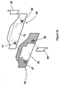
station 56 have a cross section as illustrated inFigure 8 . This Figure is not to scale or in proportion but rather schematic so as to more clearly illustrate the relative disposition of the sheets. Of particular interest is that edges 46 and 47 extend beyond the overlap that exists between the back-to-back sheets 15. Thesesheets 15 form a first pair and theopposed sheets Sheets - After leaving
station 56 the layered combination of sheets are cut transversely along respective cut lines that extend transversely throughslots 22. Whilesheets sheets 15 are only cut acrosstabs 21. Importantly, these tabs do not overlie or overlap with either ofsheets sheets 15 and either ofsheets - In the case of automated manufacture it is inevitable that the equipment used will operate across a range of tolerances and will progressively wear. With time, there is an increasing risk of non-ideal behaviour, one of which is the puncturing of one or more of
sheets sheets sheets 15. The result is a manufacturing process that is less sensitive to the accuracy of the cut and, as such, one which lends itself to automation and higher yields. - The cutting of the sheets provides a plurality of electrode units having a cross section the same as that shown in
Figure 8 and a length equal to the distance between the centres ofadjacent slots 22. These plurality of electrode units are stacked back-to-back so that the back ofsheet respective sheet - Once the stack is formed, all of
tabs 21 are abutted and ultrasonically welded together and all oftabs 63 are abutted and ultrasonically welded together. An example of a stack is schematically illustrated inFigure 13 . - In an alternative embodiment, the layered combination of sheets that leaves
station 56 is not cut but, rather, rolled in a flat stack that has an initial width which is the distance betweenadj acent slots 22. Once rolled, the sheets take the form illustrated inFigure 12 . That is, the rolling occurs along a transverse axis andtabs ultrasonic weld 66 to the roll. While this embodiment is concerned with the rolling of four coated aluminium sheets, in other embodiments more sheets, and the required separator sheets, are used. - An alternative approach is to spiral wind the layers and then flatten them.
- In further embodiments the layered combination of sheets that leaves
station 56 is not cut but, rather, folded in a z-stack with the folds being made along transverse fold lines that extend through the slots. That is to say, that the sheets are concertinaed. Again, use is made of an ultrasonic weld or other retention means for retaining the stack in a flattened configuration. - The above embodiments have only described the use of many separate aluminium sheets that are combined. However, in other preferred embodiments use is made of different combinations. For example,
Figure 9 is a cross sectional view similar to that ofFigure 8 where corresponding features are denoted by corresponding reference numerals. In this embodiment, rather than using two back-to-back sheets 15, use is made of a single foldedsheet 15. This folded sheet includes two separate carbon strips, one each side of the fold. However, in other embodiments, the sheet includes a single carbon strip that is centrally folded upon folding of the sheet as a whole. - Another example is provided in
Figure 10 wheresheet 15 includes a carbon coating on both sides and, as such, only a single thickness ofsheet 15 is required. A further example is shown inFigure 11 wheresheets common fold line 65. - A further example is illustrated in
Figure 11 a where use is made of two folded electrodes. - Other combinations are possible as would be now understood from the teaching herein.
- In all these embodiments, however,
tabs 21 extend transversely fromedges 47 ofsheets tabs 63 extend transversely fromedges 46 ofsheets tabs 21. The combination ofsheets 15 form a first electrode of a first capacitive cell of the supercapacitor while the combination ofsheets separate sheets 15 and good electrical contact is established betweensheets sheets 15 and both ofsheets sheets sheets 15 andsheets - The next stage in the manufacturing process is to trim the
tabs Figure 14 where acapacitive cell 70 is illustrated. This cell has had the tabs trimmed to about half their initial longitudinal extent. In other embodiments the trimming removes a different amount of the tabs. For example, in the embodiment illustrated inFigure 14a one end of each tab is trimmed at an acute angle. This is done to better improve the packing density of the overall supercapacitor. That is, such a supercapacitor uses a number of the cells in a folded configuration and, depending upon the nature of the folding used, there is advantage to be gained by judicious trimming at this stage in the process. This effect will be discussed further below. - In another example illustrated in
Figure 14b , the tabs are trimmed symmetrically about the centre line of the cell. More particularly, one end of both tabs are trimmed at an acute angle, while the other end of both tabs is trimmed at an obtuse angle. - While it is usual to have the tabs equally trimmed, in some embodiments this does not occur. Additionally, in this embodiment the tabs are trimmed from the centre to one end. However, in alternative embodiments, the remaining tab is central, not offset.
-
Tabs rectangular terminals Figure 16 . The terminals are made from aluminium and extend transversely outwardly from the respective tabs and away from each other. The attachment in this embodiment is by way of ultrasonic welding, although in other embodiments use is made of conductive adhesives, soldering, or other like means. -
Terminals - As best shown in
Figure 15 ,cell 70, which is illustrated in ghosted outline, is intended to be placed on aflexible laminate sheet 71. The sheet is symmetrical aboutfold line 72 and includes four spaced apartcircular openings sheet 71 that lie above and belowline 72 will be referred to asportion 77 andportion 78 respectively. - Based upon the teaching herein it will be appreciated by those skilled in the art that
sheet 71 need not be the shape shown inFigure 15 . For example, twoalternative sheets 71 are illustrated inFigures 15a and15b respectively. - In the
Figure 15 embodiment,openings - As will become clear from the following description, the terminals are to be sealingly engaged with
sheet 71 at least about the periphery ofopenings terminals sheet 71. -
Sheet 71 includes an internal aluminium layer to provide high barrier properties to the ingress and egress of fluids through and sheet. Moreover, the sheet includes at least one outer layer that is thermoformable into sealing engagement with itself andterminals preferred sheet 71 is disclosed in Australian provisional patent application no.PQ8700 filed on 10 July, 2000 -
Cell 70 is placed onsheet 71 such that it lies only onportion 77 and withterminals respective openings Portion 78 is then folded alongline 72 back overcell 70 andportion 77. The resultant configuration is illustrated inFigure 17 . This figure also includes cross-hatching to indicate the threeareas sheet 71 to which pressure and heat are subsequently applied to sealcell 70 withinsheet 71. - The heat applied to
area 81 is sufficient in intensity and duration to cause theportions terminals portions area 81 provide, in combination, a laminate of substantially uniform thickness. This facilitates the application of the heat and pressure toarea 81 and improves the sealing betweenportions area 81 and, hence, allows more precise control of the heating and sealing process. This, in turn, further enhances the applicability of the present manufacturing method to automation. - Preferably,
cell 70 is wetted thoroughly with electrolyte prior to placement onsheet 71. In other embodiments, however, the heat sealing is a two step operation and the electrolyte is deposited into the housing formed bysheet 71 between those two steps. - It will be understood by the skilled address that the electrolyte allows for ionic conduction between the electrodes in the cell and that a variety of electrolytes are available.
- The heat that is applied to
sheet 71 is also sufficient to affect sealing engagement betweensheet 71 andterminals areas portion 77 ofsheet 71 is also thermoformed into sealing engagement with the adjacent surfaces ofterminals areas - As the planar area of
terminals openings cell 70 onsheet 71. -
Area thick area 81, similar advantages apply to the heating and sealing operation. - In this embodiment, and as shown in
Figure 18 ,sheet 71 includes anouter layer 85 of PET, anintermediate aluminium layer 86 and aninner layer 87 of polyethylene. Upon the application of heat toareas layer 87 softens preferentially to the other layers and bonds to the adjacent terminal. It is emphasised that this Figure, like the others, is not to scale and that the proportions have been exaggerated to more clearly illustrate the features of the preferred embodiment. - The heat sealing of
sheet 71 to the terminals will be described with reference toFigure 18 . That is, two opposed heated plates (not shown) are progressed into engagement with theopposite areas 82. The plates apply both heat and compressive force to the material that is sandwiched between the plates. The heat softenslayers sheet 71 being flattened inarea 82. - After the heat source is removed from all areas, and the resultant structure allowed to cool,
sheet 71 provides a sealedhousing 88 forcell 70 and the electrolyte. It is important to note, however, that both planar sides of bothterminals openings - As illustrated in
Figure 19 , two likecells 70 are contained withinrespective housings 88 and are stacked together and attached to each other. That is, terminal 67 of one cell is ultrasonically welded toterminal 67 of the other of the cells. This welding is possible as access to both sides of the terminals is provided. That is, one contact of the welder is engaged with the outer face ofterminal 67 of one of the cells, while the other contact of the welder is engaged with the outer face of the terminal 67 of the other of the cells. The contacts are then biased toward each other to abut the opposed faces of theterminals 67. The welder is then actuated to weld the abutted terminals together. - The two
free terminals 68 provide a site for attachment ofrespective aluminium contact Figure 19 , the contacts are attached opposite to each other in that they are on the outermost surfaces of the terminals. Additionally, the contacts extend away from the terminals and each other to minimise any risk of inadvertent electrical contact with each other. - Once the welding has been completed,
housings 88 are connected to form apackage 92, as best shown inFigure 20 . This package is folded initially about parallel spaced apart foldlines Figure 17 . The fold lines all pass throughtabs thicker terminals terminals - As shown in
Figure 21 , the folding is such that theterminals - In other embodiments,
area 81 ofsheet 71 is greater to provide a greater minimum seal path for the device. This is required for some combinations of: - 1. Performance specification - such as raised operational temperatures;
- 2. Type of
sheet 71; and - 3. Type of electrolyte.
- In such embodiments there is some overlap between the portions that are folded back over the cell. However, there is no overlap of
terminals -
Package 92 is also folded along fold lines 96. The folded portions overlap with the cell and are folded onto the same side of the cell as the other folded portions. In this embodiment all the folded portions do not overlap each other, although in other embodiments this does occur. - It will be appreciated that it is not critical if the fold along
lines 96 causes some overlap, as this portion is relatively thin, being only two layers ofsheet 71. The thickest folded components areterminals - Reference is now made to
Figure 21 which showspackage 92 as it is further folded. As illustrated, all the folded portions are folded inwardly and across the cell to provide smooth continuous outer faces 98. That is, all the folded portions are contained and captured between theseparate housings 88 and are not exposed. Accordingly, the risk of the folded portions returning to their original unfolded configurations is minimised. It also provides a substantially clean and planar exterior surface to minimise the risk of the housing catching or fouling with other objects inadvertently during the automated manufacturing process. - In this folded
configuration contacts package 92. These are subsequently deformed to extend back along their respective lengths and toward each other. An additional deformation is then applied such that the contacts extend outwardly from between the foldedhousing 88, as best shown inFigure 1 . - A skilled addressee will note from
Figure 21 that the twoterminals 68 have exposed faces that are closely adjacent in the folded package. In some embodiments these exposed faces are coated with an electrically insulating material to prevent any inadvertent contact of the terminals. An example of such a material is an epoxy resin. - All the heat welds that are performed to package 92 are to planar surfaces. That is,
areas - The embodiment described above and as illustrated in the drawings, the two like
cells 88 are connected in series. In other embodiments supercapacitor 1 include more than two cells in series. Infurther embodiments cells 88 are connected in parallel. Moreover, some embodiments include a hybrid series/parallel combination. -
Package 92, in the folded configuration, is received withinframe 3 and captively retained in that configuration. In the present embodiment,tabs frame 3 are movable between an open configuration and a closed configuration (as shown inFigure 1 ) in which the package is respectively allowed and prevented from movement through the opening. The tabs are integrally formed with the frame and are deformed into the open and the closed configurations. Asframe 3 is formed from tinned metal, the deformation oftabs package 92 is received within the frame. - As
tabs -
Frame 3 not only applies a compressive force tohousing 2 to retain it in the folded configuration, but also takes the mechanical load fromcontacts - Reference is now made to the embodiment of the invention illustrated in
Figures 22 to 25 where corresponding features are denoted by corresponding reference numbers. For the sake of clarity, not all reference numerals have been reproduced. - As best shown in
Figure 23 ,openings fold line 72, are generally square as opposed to the round openings of the other embodiment. Additionally,tabs - This configuration allows the heating and sealing operation to occur across a large
continuous area 81, as shown inFigure 24 . That is, only a single area has heat and pressure applied to it, as opposed to the threeseparate areas Figure 17 embodiment. - Additionally, once the heating and sealing has been affected, the
housing 88 ofFigure 24 is cut along atrim line 99 that is shown in the Figure as a broken line. Two of thehousings 88 are shown inFigure 25 . - The initial heating and sealing across a continuous region, and later trimming, provides the following advantages:
- 1. The greater area of
sheet 71 makes it easier to handle and manoeuvre during the heating and sealing operation; - 2. The cutting allows a greater amount of
sheet 71 to be removed, hence increasing the packing density of the resultant device; - 3. The
trim line 99 does not pass through any region wheresheet 71 overliesterminals aluminium layer 86 during the cutting operation is minimised if not avoided. - 4. As the cutting occurs after the sealing, the manufacturing is less sensitive to the initial positioning of
cell 70 onsheet 71, the length ofterminals terminals respective tabs - Once the cutting only
trim line 99 has occurred, as shown inFigure 25 ,terminals contacts cells 88 ofFigure 25 are attached and folded similarly to the embodiment shown inFigures 19 to 21 . The folded structure is then placed within a frame to maintain that folded configuration and to facilitate mounting of the resultant supercapacitor. - The process of producing the supercapacitor of the preferred embodiments described above is extremely well suited to mass production and repeatability of manufacture. This is because the process:
- 1. Allows use of continuous feeds of sheet material;
- 2. Is robust because the slots:
- a) Prevent undesired short circuits between the electrodes due to the cutting operation; and
- b) Allow indexing of the continuous materials. This, in turn, allows an accurate progression of these materials as the rollers and other tensioning equipment is able to be automatically calibrated;
- 3. Allows great variation in the parameters of the end product. That is, there is little complication involved in using more or less coated aluminium layers or layers of different thickness or composition;
- 4. All the heat welds are performed on planar surfaces which eliminates the variations and cavities from which prior art heat welding suffers.
- 5. All the heat welds are large in area to minimise the risk of leakage or subsequent contamination.
- 6. Provides relatively large planar terminals and small openings in the housing. As such, the electrical resistance of the terminal is low without the need to compromise the heat seal. The primary factor for selection of the terminal thickness is the desired overall thickness of the packaging, not the effectiveness of the seal.
- 7. Allows a wide tolerance of heat sealing temperatures when using the preferred housing material.
- 8. Ensures that the electrode tabs extend outwardly and away from each other which substantially reduces the risk of contact between the tabs.
- This increased robustness of the preferred embodiment provides a supercapacitor that is extremely cost effective to produce as it allows the use of automated manufacturing techniques to a level beyond known processes. Moreover, it allows the use of soft packaging that is more versatile both in manufacture and use. Also, it provides long seal paths that ameliorate leakage issues that plague the prior art devices.
- Although the invention has been described with reference to specific examples it will be appreciated by those skilled in the art that it may be embodied in many other forms.
Claims (12)
- A combination of sheets (15,16,39,40) for forming an energy storage device, the combination of sheets comprising an electrode sheet (15,16) sandwiched between two opposed separator sheets (39,40), the electrode sheet being formed from a continuous conductive sheet having a first face, a second face opposite the first face and a plurality of longitudinally spaced apart transverse slots (22) extending between the faces, wherein the slots have a transverse extent less than the predetermined transverse width of the conductive sheet to define a plurality of sequentially linked first electrode plates (25), wherein the transverse slots extend linearly between open ends (23) that are co-terminous with an edge of the conductive sheet and closed ends (24) intermediate the edges of the conductive sheet wherein the first electrode plates each include a tab portion (21) that extends transversely beyond the separator and wherein the separator sheets (39,40) are bonded together at the transverse slots (22);
- A method for forming an energy storage device from a continuous longitudinally extending conductive sheet (15) of a predetermined transverse width, the method including:forming a plurality of longitudinally spaced apart transverse slots (23) in the sheet, wherein the slots have a transverse extent less than the predetermined transverse width to define a plurality of sequentially linked first electrode plates (25), wherein the transverse slots extend linearly between open ends that are co-terminous with an edge of the conductive sheet and closed ends intermediate the edges of the conductive sheet;sandwiching the electrode plates between two opposed separator sheets (39,40), the plates each including a tab portion (21) that extends transversely beyond the separator, wherein the separator sheets are bonded together at the transverse slots;separating the electrode plates (25);connecting the tab portions (21) to each other to electrically connect the electrode plates;overlapping and partially sandwiching the first electrode plates with at least one second electrode sheet (57, 58) collectively formed from a plurality of second electrode plates;disposing the electrode plates within a housing containing an electrolyte for allowing ionic conduction between the plates; andconnecting two terminals to the respective pluralities of electrode plates for allowing external electrical connection to those plates.
- A method according to claim 2 wherein the sheet includes two opposite transverse edges that are spaced apart by the predetermined width and the method includes forming the slots such that they extend from one of the transverse edges and terminate adjacent to the other edge.
- A method according to claim 2 wherein the separator sheets are retained in tensioned engagement with the plates.
- A method according to claim 2 wherein the bonding is by way of heat sealing.
- A method according to claim 2 wherein the bonding is by way of heat welding.
- A method according to claim 5 or claim 6 wherein the heat sealing or welding extends longitudinally across substantially all the slot.
- A method according to claim 5 or claim 6 wherein the heat sealing or welding extends transversely across substantially all the slot.
- A method according to claim 5 or claim 6 wherein the heat sealing is affected at two or more spaced apart locations in the slot.
- A method according to claim 2 including alternately stacking the first and the second plurality of plates with each other.
- A method according to claim 10 including the step of stacking the first and the second plurality of plates with each other in a single stack.
- A method according to claim 2 including the step of applying a coating to the sheet, wherein the coating includes activated carbon particles and a binder.
Applications Claiming Priority (3)
| Application Number | Priority Date | Filing Date | Title |
|---|---|---|---|
| AUPR194400 | 2000-12-06 | ||
| AUPR1944A AUPR194400A0 (en) | 2000-12-06 | 2000-12-06 | An energy storage device |
| PCT/AU2001/001613 WO2002047097A1 (en) | 2000-12-06 | 2001-12-06 | An energy storage device |
Publications (3)
| Publication Number | Publication Date |
|---|---|
| EP1348223A1 EP1348223A1 (en) | 2003-10-01 |
| EP1348223A4 EP1348223A4 (en) | 2008-03-26 |
| EP1348223B1 true EP1348223B1 (en) | 2013-03-20 |
Family
ID=3825979
Family Applications (1)
| Application Number | Title | Priority Date | Filing Date |
|---|---|---|---|
| EP01999948A Expired - Lifetime EP1348223B1 (en) | 2000-12-06 | 2001-12-06 | Combination of sheets and method for forming an energy storage device |
Country Status (6)
| Country | Link |
|---|---|
| US (3) | US7054139B2 (en) |
| EP (1) | EP1348223B1 (en) |
| JP (2) | JP5030365B2 (en) |
| AU (2) | AUPR194400A0 (en) |
| CA (1) | CA2431216A1 (en) |
| WO (1) | WO2002047097A1 (en) |
Cited By (1)
| Publication number | Priority date | Publication date | Assignee | Title |
|---|---|---|---|---|
| US11721494B2 (en) | 2017-02-20 | 2023-08-08 | The Research Foundation For The State University Of New York | Multi-cell multi-layer high voltage supercapacitor apparatus including graphene electrodes |
Families Citing this family (28)
| Publication number | Priority date | Publication date | Assignee | Title |
|---|---|---|---|---|
| AUPS119502A0 (en) | 2002-03-19 | 2002-04-18 | Energy Storage Systems Pty Ltd | An electrolyte for an energy storage device |
| US7040716B2 (en) * | 2002-08-29 | 2006-05-09 | Railway Technical Research Institute | Anti-lock brake system for vehicles |
| US7586736B2 (en) * | 2005-07-11 | 2009-09-08 | Micro Power Electronics Inc. | Electrical insulation system and method for electrical power storage component separation |
| IL172146A0 (en) * | 2005-11-23 | 2006-04-10 | Cellergy Ltd | Thermal barrier for surface mounting |
| KR100861713B1 (en) * | 2006-02-09 | 2008-10-06 | 주식회사 엘지화학 | Battery module |
| US7433174B2 (en) * | 2006-07-06 | 2008-10-07 | Maxwell Technologies, Inc. | Method of making, apparatus, and article of manufacturing for an electrode termination contact interface |
| US20080013254A1 (en) * | 2006-07-14 | 2008-01-17 | John Miller | Method of making, apparatus, and article of manufacture for an ultracapacitor electrode termination contact interface |
| JP4495751B2 (en) | 2007-07-24 | 2010-07-07 | 太陽誘電株式会社 | Method for manufacturing electrochemical device |
| FR2927728A1 (en) * | 2008-02-19 | 2009-08-21 | Batscap Sa | ELECTRIC POWER STORAGE ASSEMBLY MULTIPIST. |
| FR2927727B1 (en) * | 2008-02-19 | 2017-11-17 | Batscap Sa | MULTIBOBIN ELECTRIC ENERGY STORAGE ASSEMBLY. |
| KR100930207B1 (en) * | 2009-03-16 | 2009-12-07 | 삼성전기주식회사 | Manufacturing method of mobile communication terminal, mobile communication terminal case and mobile communication terminal using same |
| US8760840B2 (en) | 2010-04-14 | 2014-06-24 | Tdk Corporation | Electrochemical device and manufacturing method thereof, circuit board and housing tray |
| JP5035397B2 (en) | 2010-07-28 | 2012-09-26 | Tdk株式会社 | Electrochemical devices |
| EP2523202A1 (en) * | 2011-05-13 | 2012-11-14 | Eika, S.Coop | Electrical double - layer capacitor, and method for manufacturing such a capacitor |
| US20120313586A1 (en) * | 2011-06-09 | 2012-12-13 | Fastcap Systems Corporation | Automotive electrified drive train systems with high temperature rechargeable energy storage device |
| JP5870588B2 (en) * | 2011-09-28 | 2016-03-01 | Tdk株式会社 | Power storage element, power storage device, and circuit board |
| WO2013094423A1 (en) * | 2011-12-22 | 2013-06-27 | 株式会社村田製作所 | Accumulator device |
| US9564275B2 (en) * | 2012-03-09 | 2017-02-07 | The Paper Battery Co. | Supercapacitor structures |
| EP2973836A4 (en) | 2013-03-15 | 2017-03-22 | The Paper Battery Company, Inc. | Energy storage structures and fabrication methods thereof |
| US9583277B2 (en) | 2013-09-30 | 2017-02-28 | The Paper Battery Company, Inc. | Ultra-capacitor structures and electronic systems with ultra-capacitor structures |
| EP3161899A4 (en) | 2014-06-30 | 2017-12-27 | Black & Decker Inc. | Battery pack for a cordless power tools |
| US10312028B2 (en) | 2014-06-30 | 2019-06-04 | Avx Corporation | Electrochemical energy storage devices and manufacturing methods |
| DE102015218533A1 (en) * | 2015-09-28 | 2017-03-30 | Robert Bosch Gmbh | Process for producing an electrode composite |
| CN109155202B (en) | 2016-05-20 | 2021-03-09 | 阿维科斯公司 | Multi-cell supercapacitor |
| CN108009387A (en) * | 2017-12-29 | 2018-05-08 | 中国电子科技集团公司信息科学研究院 | A kind of compound energy analogue system and management strategy |
| US12136837B1 (en) * | 2020-12-08 | 2024-11-05 | Bobbie Wilson | Charge balancing of parallel strings with zener diode and light emitting diode between cell terminal of the battery strings |
| CN115149208B (en) * | 2022-08-03 | 2023-06-02 | 山东华太新能源电池有限公司 | Automatic pipe rolling equipment for positive diaphragm pipe |
| CN221687394U (en) * | 2023-12-06 | 2024-09-10 | 上海法雷奥汽车电器系统有限公司 | Capacitor bracket for motor controller |
Citations (2)
| Publication number | Priority date | Publication date | Assignee | Title |
|---|---|---|---|---|
| JPH02130907A (en) * | 1988-11-11 | 1990-05-18 | Nichicon Corp | Manufacture of laminated electrolytic capacitor |
| GB2270720A (en) * | 1992-09-17 | 1994-03-23 | T & N Technology Ltd | Manufacturing plain bearings. |
Family Cites Families (50)
| Publication number | Priority date | Publication date | Assignee | Title |
|---|---|---|---|---|
| DE2405158A1 (en) * | 1974-02-04 | 1975-08-07 | Philips Patentverwaltung | Electrolytic layered capacitor with cover stack holding - has housing and cover of rectangular cross section with cover mounted holders |
| JPS5945212B2 (en) * | 1978-10-19 | 1984-11-05 | 松下電器産業株式会社 | Aluminum electrolytic capacitor |
| US4267566A (en) * | 1979-04-02 | 1981-05-12 | Sprague Electric Company | Sealed flat electrolytic capacitor and method |
| JPS603120A (en) | 1983-06-21 | 1985-01-09 | 株式会社村田製作所 | Method of producing electric double layer capacitor |
| US4540642A (en) * | 1984-03-30 | 1985-09-10 | The United States Of America As Represented By The United States Department Of Energy | Cell design for lithium alloy/metal sulfide battery |
| JPH02180907A (en) * | 1989-01-04 | 1990-07-13 | Kawasaki Steel Corp | Production of styrene oligomer |
| JP2973499B2 (en) * | 1990-09-13 | 1999-11-08 | 松下電器産業株式会社 | Chip type solid electrolytic capacitor |
| US5154989A (en) * | 1991-09-04 | 1992-10-13 | Medtronic, Inc. | Energy storage device |
| US5450279A (en) | 1993-05-19 | 1995-09-12 | Matsushita Electric Industrial Co., Ltd. | Electric double layer capacitor |
| US5581438A (en) * | 1993-05-21 | 1996-12-03 | Halliop; Wojtek | Supercapacitor having electrodes with non-activated carbon fibers |
| JP3277413B2 (en) * | 1993-08-17 | 2002-04-22 | ソニー株式会社 | Prismatic battery |
| JP3605851B2 (en) * | 1994-05-31 | 2004-12-22 | ソニー株式会社 | Rechargeable battery |
| US5532083A (en) * | 1994-07-26 | 1996-07-02 | Mccullough; Francis P. | Flexible carbon fiber electrode with low modulus and high electrical conductivity, battery employing the carbon fiber electrode, and method of manufacture |
| JPH0896802A (en) * | 1994-09-27 | 1996-04-12 | Sony Corp | Method for manufacturing secondary battery electrode |
| US5518836A (en) * | 1995-01-13 | 1996-05-21 | Mccullough; Francis P. | Flexible carbon fiber, carbon fiber electrode and secondary energy storage devices |
| DE69636710T2 (en) * | 1995-03-03 | 2007-10-04 | Rohm Co. Ltd., Kyoto | FIXED ELECTROLYTE CONDENSER AND ITS MANUFACTURING METHOD |
| JPH097893A (en) * | 1995-06-23 | 1997-01-10 | Matsushita Electric Ind Co Ltd | Electric double layer capacitor and method of manufacturing the same |
| US5926361A (en) * | 1995-09-28 | 1999-07-20 | Westvaco Corporation | High power density double layer energy storage devices |
| JPH09213377A (en) * | 1996-01-30 | 1997-08-15 | Ricoh Co Ltd | Prismatic battery |
| AU3397997A (en) * | 1996-06-19 | 1998-01-07 | Mixon, Inc. | Separator and method of reinforcement application |
| JPH1070052A (en) | 1996-08-28 | 1998-03-10 | Toyota Motor Corp | Electric double layer capacitor |
| JPH1079254A (en) * | 1996-09-04 | 1998-03-24 | Denso Corp | Prismatic battery |
| JPH09106806A (en) * | 1996-10-18 | 1997-04-22 | Denso Corp | Battery |
| DE69719911T2 (en) * | 1996-10-21 | 2003-09-11 | Japan Storage Battery Co. Ltd., Kyoto | Method of manufacturing a battery electrode |
| JPH10172565A (en) * | 1996-12-11 | 1998-06-26 | Mitsubishi Cable Ind Ltd | Sheet lithium secondary battery |
| EP0854529A1 (en) | 1996-12-05 | 1998-07-22 | Mitsubishi Cable Industries, Ltd. | Sheet type lithium secondary battery |
| JP3511443B2 (en) * | 1996-12-20 | 2004-03-29 | 株式会社リコー | Battery device |
| US5882817A (en) * | 1997-03-03 | 1999-03-16 | Space Systems/Loral, Inc. | Battery cell design for a bipolar rechargeable battery |
| JP4078489B2 (en) * | 1997-04-01 | 2008-04-23 | 株式会社ジーエス・ユアサコーポレーション | Battery manufacturing method |
| US5926362A (en) * | 1997-05-01 | 1999-07-20 | Wilson Greatbatch Ltd. | Hermetically sealed capacitor |
| US5963418A (en) * | 1997-05-02 | 1999-10-05 | Cm Components, Inc. | Multiple anode high energy density electrolytic capacitor |
| AUPO709497A0 (en) * | 1997-05-30 | 1997-06-26 | Commonwealth Scientific And Industrial Research Organisation | Terminal connection to double layer capacitors |
| JPH11121305A (en) * | 1997-10-17 | 1999-04-30 | Okamura Kenkyusho:Kk | Electric double layer capacitor with improved filling efficiency |
| TW385558B (en) | 1998-01-05 | 2000-03-21 | Voltec Pte Ltd | A battery |
| US6042966A (en) * | 1998-01-20 | 2000-03-28 | Valence Technology, Inc. | Battery terminal insulation |
| US6145280A (en) * | 1998-03-18 | 2000-11-14 | Ntk Powerdex, Inc. | Flexible packaging for polymer electrolytic cell and method of forming same |
| JP2000012390A (en) * | 1998-06-22 | 2000-01-14 | Asahi Glass Co Ltd | Electrochemical element, method for manufacturing the same, and manufacturing apparatus |
| JP2000090965A (en) * | 1998-09-11 | 2000-03-31 | Toshiba Battery Co Ltd | Cylindrical alkaline secondary battery |
| AUPP596598A0 (en) * | 1998-09-16 | 1998-10-08 | Energy Storage Systems Pty Ltd | A flexible charge storage device |
| US6631072B1 (en) * | 1998-12-05 | 2003-10-07 | Energy Storage Systems Pty Ltd | Charge storage device |
| JP2000182895A (en) * | 1998-12-15 | 2000-06-30 | Ngk Insulators Ltd | Electric double layer capacitor |
| US6198623B1 (en) * | 1999-01-29 | 2001-03-06 | Telcordia Technologies, Inc. | Carbon fabric supercapacitor structure |
| JP4260982B2 (en) * | 1999-05-10 | 2009-04-30 | 日東電工株式会社 | Non-aqueous electrolyte battery |
| JP2001076971A (en) * | 1999-09-03 | 2001-03-23 | Nec Corp | Electric double-layer capacitor and manufacture of the same |
| KR100323477B1 (en) * | 1999-11-12 | 2002-02-07 | 김선욱 | Condenser |
| RU2170468C1 (en) * | 2000-04-10 | 2001-07-10 | Мирзоев Рустам Аминович | Electrochemical energy storage of high specific power and its plate |
| KR100487069B1 (en) * | 2000-04-12 | 2005-05-03 | 일진나노텍 주식회사 | Supercapacitor using electrode of new material and manufacturing method the same |
| JP2004513529A (en) * | 2000-11-09 | 2004-04-30 | エフオーシー フランケンブルク オイル カンパニー エスト. | Supercapacitor and method of manufacturing the supercapacitor |
| JP2002299161A (en) * | 2001-03-29 | 2002-10-11 | Matsushita Electric Ind Co Ltd | Composite electronic components |
| WO2009028035A1 (en) | 2007-08-27 | 2009-03-05 | Mitsubishi Electric Corporation | Method and device for diagnosing remaining lifetime of switchgear |
-
2000
- 2000-12-06 AU AUPR1944A patent/AUPR194400A0/en not_active Abandoned
-
2001
- 2001-12-06 EP EP01999948A patent/EP1348223B1/en not_active Expired - Lifetime
- 2001-12-06 WO PCT/AU2001/001613 patent/WO2002047097A1/en not_active Ceased
- 2001-12-06 AU AU2002221337A patent/AU2002221337A1/en not_active Abandoned
- 2001-12-06 US US10/433,160 patent/US7054139B2/en not_active Expired - Lifetime
- 2001-12-06 JP JP2002548735A patent/JP5030365B2/en not_active Expired - Lifetime
- 2001-12-06 CA CA002431216A patent/CA2431216A1/en not_active Abandoned
-
2006
- 2006-04-06 US US11/398,672 patent/US7233482B2/en not_active Expired - Fee Related
-
2007
- 2007-04-25 US US11/790,374 patent/US7554790B2/en not_active Expired - Lifetime
-
2008
- 2008-10-03 JP JP2008258509A patent/JP2009021632A/en not_active Withdrawn
Patent Citations (2)
| Publication number | Priority date | Publication date | Assignee | Title |
|---|---|---|---|---|
| JPH02130907A (en) * | 1988-11-11 | 1990-05-18 | Nichicon Corp | Manufacture of laminated electrolytic capacitor |
| GB2270720A (en) * | 1992-09-17 | 1994-03-23 | T & N Technology Ltd | Manufacturing plain bearings. |
Cited By (1)
| Publication number | Priority date | Publication date | Assignee | Title |
|---|---|---|---|---|
| US11721494B2 (en) | 2017-02-20 | 2023-08-08 | The Research Foundation For The State University Of New York | Multi-cell multi-layer high voltage supercapacitor apparatus including graphene electrodes |
Also Published As
| Publication number | Publication date |
|---|---|
| JP2009021632A (en) | 2009-01-29 |
| US20070195487A1 (en) | 2007-08-23 |
| AUPR194400A0 (en) | 2001-01-04 |
| US20060193104A1 (en) | 2006-08-31 |
| US7054139B2 (en) | 2006-05-30 |
| AU2002221337A1 (en) | 2002-06-18 |
| CA2431216A1 (en) | 2002-06-13 |
| US7233482B2 (en) | 2007-06-19 |
| US20040052014A1 (en) | 2004-03-18 |
| JP5030365B2 (en) | 2012-09-19 |
| US7554790B2 (en) | 2009-06-30 |
| EP1348223A1 (en) | 2003-10-01 |
| EP1348223A4 (en) | 2008-03-26 |
| JP2004515083A (en) | 2004-05-20 |
| WO2002047097A1 (en) | 2002-06-13 |
Similar Documents
| Publication | Publication Date | Title |
|---|---|---|
| US7554790B2 (en) | Energy storage device | |
| JP4140311B2 (en) | Method for manufacturing case for power storage element | |
| US8804310B2 (en) | Electrochemical device | |
| US11527796B2 (en) | Package for power storage device | |
| JP2007335156A (en) | Electricity storage element | |
| JP5528481B2 (en) | High durability lithium ion battery | |
| EP2804240A1 (en) | Method for manufacturing packed electrode, packed electrode, secondary battery, and heat sealing machine | |
| JP7304330B2 (en) | secondary battery | |
| JP5182685B2 (en) | Multilayer secondary battery and manufacturing method thereof | |
| JP5761576B2 (en) | Multilayer battery and method for manufacturing multilayer electrode body | |
| JP2006134604A (en) | Method for manufacturing power storage device | |
| JP4655554B2 (en) | Power storage module and manufacturing method thereof | |
| JP2018041818A (en) | Power storage device, power storage module, and method for manufacturing power storage module | |
| JP2010287703A (en) | Electricity storage device | |
| CA3208451A1 (en) | Secondary battery | |
| JP5082264B2 (en) | Film-clad electrical device and method for manufacturing the same | |
| KR100910624B1 (en) | Overlapped Secondary Battery | |
| JP6832477B2 (en) | Laminated battery and manufacturing method of laminated battery | |
| JP2004515084A (en) | Connection between conductive substrate and multilayer body | |
| JP7035811B2 (en) | Resin frame manufacturing method, power storage module manufacturing method, resin frame, and power storage module | |
| JP2021174731A (en) | Method of manufacturing electrode unit | |
| JP7236422B2 (en) | BATTERY AND MANUFACTURING METHOD THEREOF | |
| JP7010904B2 (en) | Manufacturing method of power storage element | |
| JP7493970B2 (en) | Electrochemical cell and method of manufacturing same | |
| JP2020135934A (en) | Manufacturing method of power storage module |
Legal Events
| Date | Code | Title | Description |
|---|---|---|---|
| PUAI | Public reference made under article 153(3) epc to a published international application that has entered the european phase |
Free format text: ORIGINAL CODE: 0009012 |
|
| 17P | Request for examination filed |
Effective date: 20030625 |
|
| AK | Designated contracting states |
Kind code of ref document: A1 Designated state(s): AT BE CH CY DE DK ES FI FR GB GR IE IT LI LU MC NL PT SE TR |
|
| AX | Request for extension of the european patent |
Extension state: AL LT LV MK RO SI |
|
| RIN1 | Information on inventor provided before grant (corrected) |
Inventor name: JAMES, DAVID ALBERT Inventor name: SLOAN, ALINA KAY Inventor name: STEPHENS, RICHARD MICHAEL Inventor name: WILSON, STEPHEN ROBERT |
|
| RBV | Designated contracting states (corrected) |
Designated state(s): AT BE CH CY DE FR GB IT LI |
|
| RAP1 | Party data changed (applicant data changed or rights of an application transferred) |
Owner name: ENERGY STORAGE SYSTEMS LIMITED |
|
| RAP1 | Party data changed (applicant data changed or rights of an application transferred) |
Owner name: CAP-XX LIMITED |
|
| RAP1 | Party data changed (applicant data changed or rights of an application transferred) |
Owner name: CAP-XX LIMITED |
|
| A4 | Supplementary search report drawn up and despatched |
Effective date: 20080221 |
|
| RIC1 | Information provided on ipc code assigned before grant |
Ipc: H01G 9/08 20060101ALI20080215BHEP Ipc: H01G 9/04 20060101ALI20080215BHEP Ipc: H01M 2/14 20060101ALI20080215BHEP Ipc: H01G 9/004 20060101ALI20080215BHEP Ipc: H01M 10/04 20060101ALI20080215BHEP Ipc: H01G 9/155 20060101AFI20080215BHEP Ipc: H01G 9/02 20060101ALI20080215BHEP Ipc: H01M 2/02 20060101ALI20080215BHEP Ipc: H01M 2/18 20060101ALI20080215BHEP |
|
| RBV | Designated contracting states (corrected) |
Designated state(s): DE FR GB IT |
|
| 17Q | First examination report despatched |
Effective date: 20081229 |
|
| GRAP | Despatch of communication of intention to grant a patent |
Free format text: ORIGINAL CODE: EPIDOSNIGR1 |
|
| GRAS | Grant fee paid |
Free format text: ORIGINAL CODE: EPIDOSNIGR3 |
|
| REG | Reference to a national code |
Ref country code: DE Ref legal event code: R079 Ref document number: 60147798 Country of ref document: DE Free format text: PREVIOUS MAIN CLASS: H01G0009004000 Ipc: H01G0002060000 |
|
| GRAA | (expected) grant |
Free format text: ORIGINAL CODE: 0009210 |
|
| AK | Designated contracting states |
Kind code of ref document: B1 Designated state(s): DE FR GB IT |
|
| REG | Reference to a national code |
Ref country code: GB Ref legal event code: FG4D |
|
| RIC1 | Information provided on ipc code assigned before grant |
Ipc: H01G 2/06 20060101AFI20130211BHEP Ipc: H01G 9/10 20060101ALI20130211BHEP Ipc: H01M 2/02 20060101ALI20130211BHEP Ipc: H01G 11/82 20130101ALI20130211BHEP Ipc: H01G 11/74 20130101ALI20130211BHEP Ipc: H01M 10/04 20060101ALI20130211BHEP Ipc: H01G 9/16 20060101ALI20130211BHEP |
|
| REG | Reference to a national code |
Ref country code: DE Ref legal event code: R096 Ref document number: 60147798 Country of ref document: DE Effective date: 20130516 |
|
| PLBE | No opposition filed within time limit |
Free format text: ORIGINAL CODE: 0009261 |
|
| STAA | Information on the status of an ep patent application or granted ep patent |
Free format text: STATUS: NO OPPOSITION FILED WITHIN TIME LIMIT |
|
| 26N | No opposition filed |
Effective date: 20140102 |
|
| PGFP | Annual fee paid to national office [announced via postgrant information from national office to epo] |
Ref country code: IT Payment date: 20131220 Year of fee payment: 13 |
|
| REG | Reference to a national code |
Ref country code: DE Ref legal event code: R097 Ref document number: 60147798 Country of ref document: DE Effective date: 20140102 |
|
| REG | Reference to a national code |
Ref country code: FR Ref legal event code: PLFP Year of fee payment: 15 |
|
| PG25 | Lapsed in a contracting state [announced via postgrant information from national office to epo] |
Ref country code: IT Free format text: LAPSE BECAUSE OF NON-PAYMENT OF DUE FEES Effective date: 20141206 |
|
| REG | Reference to a national code |
Ref country code: FR Ref legal event code: PLFP Year of fee payment: 16 |
|
| REG | Reference to a national code |
Ref country code: FR Ref legal event code: PLFP Year of fee payment: 17 |
|
| REG | Reference to a national code |
Ref country code: DE Ref legal event code: R082 Ref document number: 60147798 Country of ref document: DE Representative=s name: D YOUNG & CO LLP, DE |
|
| PGFP | Annual fee paid to national office [announced via postgrant information from national office to epo] |
Ref country code: GB Payment date: 20201125 Year of fee payment: 20 Ref country code: FR Payment date: 20201112 Year of fee payment: 20 Ref country code: DE Payment date: 20201124 Year of fee payment: 20 |
|
| REG | Reference to a national code |
Ref country code: DE Ref legal event code: R071 Ref document number: 60147798 Country of ref document: DE |
|
| REG | Reference to a national code |
Ref country code: GB Ref legal event code: PE20 Expiry date: 20211205 |
|
| PG25 | Lapsed in a contracting state [announced via postgrant information from national office to epo] |
Ref country code: GB Free format text: LAPSE BECAUSE OF EXPIRATION OF PROTECTION Effective date: 20211205 |