EP1347622A1 - Telephone and cordless telephone - Google Patents
Telephone and cordless telephone Download PDFInfo
- Publication number
- EP1347622A1 EP1347622A1 EP01272265A EP01272265A EP1347622A1 EP 1347622 A1 EP1347622 A1 EP 1347622A1 EP 01272265 A EP01272265 A EP 01272265A EP 01272265 A EP01272265 A EP 01272265A EP 1347622 A1 EP1347622 A1 EP 1347622A1
- Authority
- EP
- European Patent Office
- Prior art keywords
- caller information
- voice
- telephone
- information
- name
- Prior art date
- Legal status (The legal status is an assumption and is not a legal conclusion. Google has not performed a legal analysis and makes no representation as to the accuracy of the status listed.)
- Withdrawn
Links
Images




Classifications
-
- H—ELECTRICITY
- H04—ELECTRIC COMMUNICATION TECHNIQUE
- H04M—TELEPHONIC COMMUNICATION
- H04M1/00—Substation equipment, e.g. for use by subscribers
- H04M1/72—Mobile telephones; Cordless telephones, i.e. devices for establishing wireless links to base stations without route selection
- H04M1/724—User interfaces specially adapted for cordless or mobile telephones
-
- H—ELECTRICITY
- H04—ELECTRIC COMMUNICATION TECHNIQUE
- H04M—TELEPHONIC COMMUNICATION
- H04M1/00—Substation equipment, e.g. for use by subscribers
- H04M1/57—Arrangements for indicating or recording the number of the calling subscriber at the called subscriber's set
- H04M1/575—Means for retrieving and displaying personal data about calling party
- H04M1/578—Means for retrieving and displaying personal data about calling party associated with a synthesized vocal announcement
Definitions
- the present invention relates to telephones and cordless telephones to which caller identification service is applicable.
- Telephones and cordless telephones supporting caller identification service features informing a callee of caller information on a display or through a voice announcement. More specifically, received caller information and caller information registered in a receiving apparatus by the callee are collated. If the received information matches the registered information, the callee is informed that the incoming call is from a registered caller on display or through a voice announcement. For example, a distinctive ring may be used, or a recorded voice message is output to inform the callee that the incoming call is from a specific caller.
- caller information announced in voice form is available to the callee only when the caller is registered in the telephone. An unregistered caller cannot thus be announced in voice form. In addition, in the conventional telephones, the incoming call ring may drown out the voice announcement on caller information.
- a telephone and cordless telephone allow caller information to be output in voice form even if a caller is unregistered.
- the telephone includes a caller information receiver for receiving an incoming call ring and caller information; a caller information memory for storing the caller information; a voice generator for generating voice data from the caller information; and an audio output unit for outputting the voice data.
- the cordless telephone has a base unit and handset.
- the base unit includes a caller information receiver for receiving an incoming call ring and caller information; a caller information memory for storing the caller information; and a voice generator for generating voice data from the caller information.
- the handset includes an audio output unit for outputting the voice data and establishes bi-directional wire communications with the base unit.
- a telephone in an exemplary embodiment of the present invention generates voice data based on received caller information regardless of whether a caller is registered or not, and announces in voice form the caller information such as a telephone number and name.
- This telephone analyses how to read out names from non-phonetic letters even when name information is data composed of non-phonetic letters, such as alphabets.
- the name information data is thus analyzed to enable it to be vocalized, and the caller's name is announced via a speaker in a base unit or handset.
- the embodiment of the present invention will be described below with reference to Figs. 1 to 6.
- the telephone of the present invention and the base unit of a cordless telephone of the present invention function similarly to each other, and thus the following description on the cordless telephone also applies to the telephone.
- Fig. 1 is a block diagram of the base unit of the cordless telephone in the embodiment.
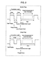
- Fig. 2 is a time chart for ringing and voice announcements from the base unit.
- Fig. 3 is a flow chart for voice-announcing caller information from the cordless telephone.
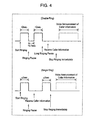
- Fig. 4 is a time chart for stopping ringing and making voice announcements from the cordless telephone.
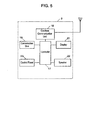
- Fig. 5 is a block diagram of the handset of the cordless telephone.
- Fig. 6 is a time chart for ringing and making voice announcements from the handset.
- cordless telephone 1 is configured with base unit 2 connected to a telephone line and at least one handset 3.
- Base unit 2 and handset 3 use bi-directional wireless communications within a predetermined distance (100 to 150m at the furthest).
- Base unit 2 transmits and receives audio signals to and from the other end of the telephone under the control of controller 4.
- Base unit 2 also establishes cordless communications with handset 3 in bi-directional through cordless communication unit 5 consisting of a wireless transmitter and wireless receiver.
- Controller 4 includes a CPU, RAM, and ROM, and controls the entire base unit 2.
- Handset 6 is wire-connected to base unit 2, and cordless communications with handset 3 (internal calls) and external communications through the telephone line (external calls) can be made by picking up and unhooking handset 6.
- Base unit 2 is also equipped with speakerphone communication unit 7. Communication without holding the handset is possible by pushing a button for speakerphone communication unit 7 for off hook. In this case, sound is output from speaker 7a in speakerphone communication unit 7.
- Base unit 2 is also equipped with answering machine 8.
- controller 4 changes switch 9 from communication circuit 10 to answering machine 8 if no off-hook operation occurs after a predetermined number of rings (for example, six rings). To place a call, dialing is effected via control panel 11. A dialed telephone number can be confirmed on display 12.
- caller information Since caller information is originally for display, data is generated in a text format. At present, the contents of caller information in Japan and North America are different. In Japan, the caller information includes only a caller's telephone number, but in North America, the caller information includes both a telephone number and name information. This means that the Japanese caller information lacks the name information included in the North American caller information. Therefore, further description refers to North American caller information which carries more pieces of information.
- Controller 4 controls the telephone such that caller information receiver 13 receives the caller information and has caller information memory 14 immediately store the caller information. Controller 4 then reads out the caller information stored in caller information memory 14, and sends the original caller information received to display 12, typically a liquid crystal display, and voice generator 15. Contents of the caller information sent to display 12 are displayed in letters, and the contents sent to voice generator 15 is converted into voice data.
- Voice generator 15 basically consists of a CPU, RAM, and ROM, and is under the control of controller 4. However, its configuration varies slightly according to the function required. For example, if the Japanese caller information changed from including telephone number information only into including both telephone number information and name information, name information would be received in data on individual phonetic letters, such as katakana . In this case, each letter would be simply converted to voice data to generate a readily comprehensible name. However, in the case of regions using alphabetic scripts for name information, such as in North America, voice announcements would not be understandable simply by vocalizing the sounds of individual letters. As a result, voice generator 15 is required to function for analyzing the pronunciation of a name from its spelling and converting these spellings to comprehensible names.
- voice generator 15 has a function for analyzing how to read names, but as described above, this function may not be needed in some areas.
- voice generator 15 analyzes how to pronounce the name as required from the name information, and converts it into voice data. Voice data is sent to speaker 7a to announce the name information in voice form.
- voice generator 15 analyzes how to read the name, and converts it to voice data to pronounce "Smith" through speaker 7a.
- the name information of up to 15 characters is sent as data. This means that long names may be cut off in the middle.
- voice generator 15 converts the data to voice data without modification and announces it through speaker 7a.
- the voice generator 15 creates voice data stating that there is no name information available, and this is announced through speaker 7a.
- voice generator 15 For example, if there is no name information since the caller withholding it, voice generator 15 generates voice data saying "Private caller", which is then announced through speaker 7a.
- voice generator 15 For example, if there is no name information in the caller information due to out of service area, voice generator 15 generates voice data stating, "Out of area", which is then announced through speaker 7.
- voice generator 15 For example, if the caller information includes only telephone number but no name information, voice generator 15 generates voice data stating "Number available", which is then announced through speaker 7a.
- Output-time monitor 16 monitors appropriate and inappropriate time for the voice announcements. Output-time monitor 16 thus monitors the cumulative length of the ring or the length of the pause between rings after receiving the ring in order to output the caller information as voice information during an interval between the rings. As shown in Fig. 2, the incoming ring may be a single ring and a double ring. Accordingly, output timing monitor 16 needs to determine the ring pattern of the incoming ring before outputting caller information in voice form. Japan uses a single ring but North America uses both a single ring and a double ring depending on areas.
- monitor 16 needs to distinguish between the short pause between a pair of rings in the double ring and the long pause after the double ring.
- the individual ring in the case of double ring, the individual ring lasts for less than 2 seconds.
- the interval between the first and second ring is less than 0.7 seconds.
- Total ring time for the double ring is 2 seconds or longer. This is followed by a 4-second pause before the next pair of rings.
- the ring In the case of single ring, the ring continues for 2 seconds or longer, followed by a four-second pause before the next single ring.
- monitor 16 determines a pause after a single or double ring based on the length of cumulative ring time and the length of the pause between rings, as shown in the flow chart in Fig. 3.
- Monitor 16 first checks whether the cumulative ring time is 2 seconds or longer (Step 1). If the cumulative time is 2 seconds or longer, monitor 16 determines that a pause is imminent, and checks whether the ring has stopped for 0.22 seconds or longer in order to provide some allowance after the ring has stopped (Step 2). If the ring stops for 0.22 seconds or longer, caller information is output in voice form (Step 3).
- monitor 16 In the case of the double ring, monitor 16 needs to determine whether a particular pause is a short pause after the first ring or a long pause after a pair of rings. If the cumulative ring time is less than 2 seconds in Step 1, monitor 16 determines that a double ring pattern is in progress if the second ring starts within 0.7 seconds (Step 4). The monitor then measures the cumulative ring time (Step 1). If the cumulative ring time exceeds 2 seconds during the double ring in Step 1, the pause time after ringing is measured (Step 2).
- Step 4 allows monitor 16 to be applicable to telephone in Japan in which the single ring terminates in 1 second.
- Monitor 16 determines that the pause after the single or double ring has arrived if the pause lasts more than 0.7 seconds.
- the caller information is then announced in voice form.
- Output-time monitor 16 monitors the cumulative time of ring and the time of the pause after the ring to ensure that the caller information is announced in voice form only between the rings.
- the caller information is announced in voice form during the pause. This voice announcement needs to be completed before the next ring starts regardless of the single or double ring. In some cases, however, the next ring starts before the voice announcement of the caller information is completed.
- Output-time monitor 16 thus monitors the time from the completion of the last ring, and mutes the incoming ring if the voice announcement of the caller information is still in progress, thereby giving priority to the voice announcement of the caller information.
- the ring is stopped immediately after receiving the caller information, or the ring is executed for a predetermined time after receiving the caller information and then stopped, as shown in Fig. 4.
- base unit 2 of cordless telephone announces caller information in voice form.
- Cordless telephone 1 of the present invention also enables handset 3 to voice-announce caller information. How caller information is output in voice form from handset 3 will be described below.
- Handset 3 establishes bi-directional cordless communications with base unit 2 via cordless communication unit 18 controlled by controller 17.
- Controller 17 includes a CPU, RAM and ROM, and controls overall operations of handset 3.
- Handset 3 has conversation unit 19 so that conversation over the phone is possible as with handset 6 of base unit 2.
- Control panel 20 operates mostly in the same manner as control panel 11 of base unit 2.
- Display 21 is smaller than display 12 of base unit 2 but has sufficient area for displaying required information.
- Handset 3 also has speaker 22 for outputting incoming rings.
- Speaker 22 outputs and stops ringing in response to on-off data for turning on and off ringing or on-off data for turning on and off the speaker in accordance with incoming data sent from base unit 2.
- Handset 3 can voice-announce the caller information between rings in the same manner as base unit 2. As shown in Fig. 6, base unit 2 outputs the ring from speaker 7a when the ring arrives via a telephone line. Simultaneously, base unit 2 sends speaker-ON data and ringing-ON data to handset 3. Handset 3 outputs the ring from speaker 22 when receiving the data from base unit 2.
- base unit 2 stops outputting ringing from speaker 7a. Simultaneously, base unit 2 sends speaker-OFF data and ringing-OFF data to handset 3. When receiving the data from base unit 2, handset 3 stops outputting the ringing from speaker 22.
- base unit 2 turns on the speaker in a predetermined time after stopping the ring and makes the announcement of the caller information in voice form from speaker 7a. Simultaneously, base unit 2 sends the speaker-ON data and voice data on caller information generated in voice generator 15 to handset 3. When handset 3 receives data from base unit 2, the speaker is turned on and the caller information is announced in voice form from speaker unit 22.
- Base unit 2 then sends the speaker-OFF data to handset 3 as soon as voice announcement of caller information is completed at base unit 2.
- handset 3 receives the data from base unit 2, voice announcement of caller information from speaker 22 is stopped.
- Fig. 6 shows the case of single ring.
- the ringing and the voice announcement of the caller information are also controlled similarly to the case of double ring as shown in Fig. 2 and Fig. 3.
- the telephone may stop the ring immediately or stopped after a predetermined number of rings after receiving the caller information in order to announce the caller information in voice form.
- Handset 3, when being mounted on base unit 2, does not output the ringing or the voice announcement of the caller information, which are thus output from base unit 2.
- base unit 2 operates merely as a relay station, and handset 3 is equipped with most telephone functions. In this case, base unit 2 may not equipped with speaker 7a if handset 3 is able to voice-announce the name information. If base unit 2 has no speaker 7a, handset 3 rings or voice-announces the caller information even when handset 3 is mounted on base unit 2.
- the telephone of the embodiment enables both the indication of the incoming caller information on a display, and the reading out of the caller's name during the pause between rings through the base unit or handset if the caller information includes the name information. Accordingly, the callee can find out immediately who is calling the callee without looking at the display.
- the telephone of the present invention announces caller information in voice form even if the caller is unregistered.
- the callee can find out who the caller is without looking at the display.
Landscapes
- Engineering & Computer Science (AREA)
- Signal Processing (AREA)
- Human Computer Interaction (AREA)
- Computer Networks & Wireless Communication (AREA)
- Telephone Function (AREA)
- Mobile Radio Communication Systems (AREA)
Abstract
A telephone reads out caller information between rings even if a caller is
unregistered. The telephone includes a caller information receiver for
receiving a call ring and caller information coming in from a caller identification
service, a caller information memory for storing the received caller information,
a voice generator for generating voice data from the caller information, a
speaker for outputting the voice data, and an output-time monitor for
monitoring appropriate and inappropriate time for announcing the caller
information in voice form.
Description
The present invention relates to telephones and cordless telephones to
which caller identification service is applicable.
Telephones and cordless telephones supporting caller identification
service features informing a callee of caller information on a display or through
a voice announcement. More specifically, received caller information and
caller information registered in a receiving apparatus by the callee are collated.
If the received information matches the registered information, the callee is
informed that the incoming call is from a registered caller on display or
through a voice announcement. For example, a distinctive ring may be used,
or a recorded voice message is output to inform the callee that the incoming call
is from a specific caller.
In conventional telephones and cordless telephones, caller information
announced in voice form is available to the callee only when the caller is
registered in the telephone. An unregistered caller cannot thus be announced
in voice form. In addition, in the conventional telephones, the incoming call
ring may drown out the voice announcement on caller information.
A telephone and cordless telephone allow caller information to be output
in voice form even if a caller is unregistered.
The telephone includes a caller information receiver for receiving an
incoming call ring and caller information; a caller information memory for
storing the caller information; a voice generator for generating voice data from
the caller information; and an audio output unit for outputting the voice data.
The cordless telephone has a base unit and handset. The base unit
includes a caller information receiver for receiving an incoming call ring and
caller information; a caller information memory for storing the caller
information; and a voice generator for generating voice data from the caller
information. The handset includes an audio output unit for outputting the
voice data and establishes bi-directional wire communications with the base
unit.
A telephone in an exemplary embodiment of the present invention
generates voice data based on received caller information regardless of whether
a caller is registered or not, and announces in voice form the caller information
such as a telephone number and name. This telephone analyses how to read
out names from non-phonetic letters even when name information is data
composed of non-phonetic letters, such as alphabets. The name information
data is thus analyzed to enable it to be vocalized, and the caller's name is
announced via a speaker in a base unit or handset.
The embodiment of the present invention will be described below with
reference to Figs. 1 to 6. The telephone of the present invention and the base
unit of a cordless telephone of the present invention function similarly to each
other, and thus the following description on the cordless telephone also applies
to the telephone.
Fig. 1 is a block diagram of the base unit of the cordless telephone in the
embodiment. Fig. 2 is a time chart for ringing and voice announcements from
the base unit. Fig. 3 is a flow chart for voice-announcing caller information
from the cordless telephone. Fig. 4 is a time chart for stopping ringing and
making voice announcements from the cordless telephone. Fig. 5 is a block
diagram of the handset of the cordless telephone. Fig. 6 is a time chart for
ringing and making voice announcements from the handset.
In Fig. 1, cordless telephone 1 is configured with base unit 2 connected to
a telephone line and at least one handset 3. Base unit 2 and handset 3 use bi-directional
wireless communications within a predetermined distance (100 to
150m at the furthest).
Caller information will be described. Since caller information is
originally for display, data is generated in a text format. At present, the
contents of caller information in Japan and North America are different. In
Japan, the caller information includes only a caller's telephone number, but in
North America, the caller information includes both a telephone number and
name information. This means that the Japanese caller information lacks the
name information included in the North American caller information.
Therefore, further description refers to North American caller information
which carries more pieces of information.
When rings comes in from the line, caller information is sent from the
caller identification service between the rings. Controller 4 controls the
telephone such that caller information receiver 13 receives the caller
information and has caller information memory 14 immediately store the caller
information. Controller 4 then reads out the caller information stored in
caller information memory 14, and sends the original caller information
received to display 12, typically a liquid crystal display, and voice generator 15.
Contents of the caller information sent to display 12 are displayed in letters,
and the contents sent to voice generator 15 is converted into voice data.
If the name information is included in the caller information received,
voice generator 15 analyzes how to pronounce the name as required from the
name information, and converts it into voice data. Voice data is sent to
speaker 7a to announce the name information in voice form.
If the received name information is alphabetic data "Smith", voice
generator 15 analyzes how to read the name, and converts it to voice data to
pronounce "Smith" through speaker 7a. In North America, the name
information of up to 15 characters is sent as data. This means that long
names may be cut off in the middle.
If the received name information is phonetic data "Taro", voice generator
15 converts the data to voice data without modification and announces it
through speaker 7a.
If the received caller information includes no name information, the
voice generator 15 creates voice data stating that there is no name information
available, and this is announced through speaker 7a.
For example, if there is no name information since the caller
withholding it, voice generator 15 generates voice data saying "Private caller",
which is then announced through speaker 7a.
For example, if there is no name information in the caller information
due to out of service area, voice generator 15 generates voice data stating, "Out
of area", which is then announced through speaker 7.
For example, if the caller information includes only telephone number
but no name information, voice generator 15 generates voice data stating
"Number available", which is then announced through speaker 7a.
Voice announcements of the caller information should not be drowned
out with ring tone when the information is announced from speaker 7a.
Output-time monitor 16 monitors appropriate and inappropriate time for the
voice announcements. Output-time monitor 16 thus monitors the cumulative
length of the ring or the length of the pause between rings after receiving the
ring in order to output the caller information as voice information during an
interval between the rings. As shown in Fig. 2, the incoming ring may be a
single ring and a double ring. Accordingly, output timing monitor 16 needs to
determine the ring pattern of the incoming ring before outputting caller
information in voice form. Japan uses a single ring but North America uses
both a single ring and a double ring depending on areas. In the case of double
ring, the voice announcement of the caller information needs to be made after
the second ring for securing sufficient time. In other words, monitor 16 needs
to distinguish between the short pause between a pair of rings in the double
ring and the long pause after the double ring.
As shown in Fig. 2, in the case of double ring, the individual ring lasts
for less than 2 seconds. The interval between the first and second ring is less
than 0.7 seconds. Total ring time for the double ring is 2 seconds or longer.
This is followed by a 4-second pause before the next pair of rings. In the case
of single ring, the ring continues for 2 seconds or longer, followed by a four-second
pause before the next single ring.
Accordingly, monitor 16 determines a pause after a single or double ring
based on the length of cumulative ring time and the length of the pause
between rings, as shown in the flow chart in Fig. 3. Monitor 16 first checks
whether the cumulative ring time is 2 seconds or longer (Step 1). If the
cumulative time is 2 seconds or longer, monitor 16 determines that a pause is
imminent, and checks whether the ring has stopped for 0.22 seconds or longer
in order to provide some allowance after the ring has stopped (Step 2). If the
ring stops for 0.22 seconds or longer, caller information is output in voice form
(Step 3).
In the case of the double ring, monitor 16 needs to determine whether a
particular pause is a short pause after the first ring or a long pause after a pair
of rings. If the cumulative ring time is less than 2 seconds in Step 1, monitor
16 determines that a double ring pattern is in progress if the second ring starts
within 0.7 seconds (Step 4). The monitor then measures the cumulative ring
time (Step 1). If the cumulative ring time exceeds 2 seconds during the double
ring in Step 1, the pause time after ringing is measured (Step 2).
The operation in Step 4 allows monitor 16 to be applicable to telephone
in Japan in which the single ring terminates in 1 second. Monitor 16
determines that the pause after the single or double ring has arrived if the
pause lasts more than 0.7 seconds. The caller information is then announced
in voice form. Output-time monitor 16 monitors the cumulative time of ring
and the time of the pause after the ring to ensure that the caller information is
announced in voice form only between the rings.
In Fig. 2, the caller information is announced in voice form during the
pause. This voice announcement needs to be completed before the next ring
starts regardless of the single or double ring. In some cases, however, the next
ring starts before the voice announcement of the caller information is
completed. Output-time monitor 16 thus monitors the time from the
completion of the last ring, and mutes the incoming ring if the voice
announcement of the caller information is still in progress, thereby giving
priority to the voice announcement of the caller information.
In order to avoid overlap in time between the voice announce of the
caller information from speaker 7a and the ring, the ring is stopped
immediately after receiving the caller information, or the ring is executed for a
predetermined time after receiving the caller information and then stopped, as
shown in Fig. 4.
In the above descriptions, base unit 2 of cordless telephone announces
caller information in voice form. Cordless telephone 1 of the present invention
also enables handset 3 to voice-announce caller information. How caller
information is output in voice form from handset 3 will be described below.
In Fig. 5, handset 3 establishes bi-directional cordless communications
with base unit 2 via cordless communication unit 18 controlled by controller 17.
Controller 17 includes a CPU, RAM and ROM, and controls overall operations
of handset 3. Handset 3 has conversation unit 19 so that conversation over
the phone is possible as with handset 6 of base unit 2. Control panel 20
operates mostly in the same manner as control panel 11 of base unit 2.
Display 21 is smaller than display 12 of base unit 2 but has sufficient area for
displaying required information. Handset 3 also has speaker 22 for outputting
incoming rings. Speaker 22 outputs and stops ringing in response to on-off
data for turning on and off ringing or on-off data for turning on and off the
speaker in accordance with incoming data sent from base unit 2.
When an incoming ring stops entering to base unit 2, base unit 2 stops
outputting ringing from speaker 7a. Simultaneously, base unit 2 sends
speaker-OFF data and ringing-OFF data to handset 3. When receiving the
data from base unit 2, handset 3 stops outputting the ringing from speaker 22.
As described with reference to Fig. 2 and Fig. 3, base unit 2 turns on the
speaker in a predetermined time after stopping the ring and makes the
announcement of the caller information in voice form from speaker 7a.
Simultaneously, base unit 2 sends the speaker-ON data and voice data on
caller information generated in voice generator 15 to handset 3. When
handset 3 receives data from base unit 2, the speaker is turned on and the
caller information is announced in voice form from speaker unit 22.
Fig. 6 shows the case of single ring. The ringing and the voice
announcement of the caller information are also controlled similarly to the case
of double ring as shown in Fig. 2 and Fig. 3. Similarly to the operation shown
in Fig. 4, the telephone may stop the ring immediately or stopped after a
predetermined number of rings after receiving the caller information in order
to announce the caller information in voice form. Handset 3, when being
mounted on base unit 2, does not output the ringing or the voice announcement
of the caller information, which are thus output from base unit 2.
In some types of cordless telephone 1, base unit 2 operates merely as a
relay station, and handset 3 is equipped with most telephone functions. In
this case, base unit 2 may not equipped with speaker 7a if handset 3 is able to
voice-announce the name information. If base unit 2 has no speaker 7a,
handset 3 rings or voice-announces the caller information even when handset 3
is mounted on base unit 2.
As described above, the telephone of the embodiment enables both the
indication of the incoming caller information on a display, and the reading out
of the caller's name during the pause between rings through the base unit or
handset if the caller information includes the name information. Accordingly,
the callee can find out immediately who is calling the callee without looking at
the display.
The telephone of the present invention announces caller information in
voice form even if the caller is unregistered. In addition, the callee can find
out who the caller is without looking at the display.
Claims (29)
- A telephone comprising:a caller information receiver for receiving an incoming call ring and caller information;a caller information memory for storing the received caller information;a voice generator for generating voice data from the stored caller information; andan audio output unit for outputting the generated voice data.
- The telephone as defined in claim 1, wherein said voice generator sets how to read a name included in name information in the caller information.
- The telephone as defined in claim 2, wherein said voice generator converts the name into voice data.
- The telephone as defined in claim 3, wherein, if the name is expressed with a phonetic letter, said voice generator converts the phonetic letter of the name into the voice data.
- The telephone as defined in claim 1, wherein, if the name information exists in the caller information, said voice generator generates voice data from a name included in the name information.
- The telephone as defined in claim 1, wherein, if the caller information does not includes name information, said voice generator generates voice data stating that there is no name information available.
- The telephone as defined in claim 6, wherein, if withholding is set to the caller information, said voice generator generates voice data stating that the caller information is withheld.
- The telephone as defined in claim 6, wherein, if out of area is set to the caller information, said voice generator generates voice data stating that the caller information is out of area.
- The telephone as defined in claim 6, wherein, if the caller information includes only telephone number information, said voice generator generates voice data stating that only a telephone number is available.
- The telephone as defined in claim 1, further comprising an output-time monitor for monitoring appropriate and inappropriate time for voice announcement of the caller information, wherein said audio output unit announcing the caller information in voice form when the incoming call ring is not output
- The telephone as defined in claim 10, wherein said output-time monitor monitors appropriate and inappropriate time for the voice announcement of the caller information in accordance with a cumulative time length of the incoming call ring.
- The telephone as defined in claim 10, wherein said output-time monitor monitors appropriate and inappropriate time for the voice announcement of the caller information through determining whether or not a pause after the incoming call ring is an interval in a double ring according to a length of the pause.
- The telephone as defined in claim 1, wherein said audio output unit stops outputting the said incoming call ring when the caller information is received, and announces the caller information in voice form.
- A cordless telephone comprising:wherein said handset establishes bi-directional wireless communications with said base unit.a base unit including:a caller information receiver for receiving an incoming call ring and caller information;a caller information memory for storing the received caller information; anda voice generator for generating voice data from the stored caller information; anda handset including a first audio output unit for outputting the voice data,
- The cordless telephone as defined in claim 14, wherein said voice generator sets how to read out a name included in name information in the caller information.
- The cordless telephone as defined in claim 15, wherein said voice generator converts the name into voice data.
- The cordless telephone as defined in claim 16, wherein, if said the name is expressed with a phonetic letter, said voice generator converts the phonetic letter of the name into voice data.
- The cordless telephone as defined in claim 14, wherein, if the name information exists in the caller information, said voice generator generates voice data of a name included in the name information.
- The cordless telephone as defined in claim 14, wherein, if the caller information does not includes name information, said voice generator generates voice data stating that there is no name information available.
- The cordless telephone as defined in claim 19, wherein, if withholding is set to the caller information, said voice generator generates voice data stating that the caller information is withheld.
- The cordless telephone as defined in claim 19, wherein, if out of area is set to said caller information, said voice generator generates voice data stating that the caller information is out of area.
- The cordless telephone as defined in claim 19, wherein, if the caller information includes only telephone number information, said voice generator generates voice data stating that only a telephone number is available.
- The cordless telephone as defined in claim 14,
wherein said base unit further includes an output-time monitor for monitoring appropriate and inappropriate time for voice announcement of the caller information, and
wherein said first audio output unit outputs the caller information in voice form when the incoming call ring is not output. - The cordless telephone as defined in claim 23, wherein said output timing monitor monitors appropriate and inappropriate time for the voice announcement of the caller information in accordance with a cumulative length of the incoming call ring.
- The cordless telephone as defined in claim 23, wherein said output-time monitor monitors appropriate and inappropriate time for the voice announcement of the caller information through determining whether or not a pause after the incoming call ring is an interval in a double ring according to a length of the pause,
- The cordless telephone as defined in claim 14, wherein said first audio output unit stops outputting the incoming call ring when the caller information is received, and announces the caller information in voice form.
- The cordless telephone as defined in claim 14, wherein said base unit further includes a second audio output unit for outputting the voice data.
- The cordless telephone as defined in claim 27,
wherein said base unit further includes an output-time monitor for monitoring appropriate and inappropriate time for voice announcement of the caller information, and
wherein said second audio output unit outputs the caller information in voice form when the incoming call ring is not output. - The cordless telephone as defined in claim 27, wherein said second audio output unit stops outputting the incoming call ring when the caller information is received, and announces the caller information in voice form.
Applications Claiming Priority (3)
| Application Number | Priority Date | Filing Date | Title |
|---|---|---|---|
| JP2000394310 | 2000-12-26 | ||
| JP2000394310A JP4734715B2 (en) | 2000-12-26 | 2000-12-26 | Telephone device and cordless telephone device |
| PCT/JP2001/011179 WO2002052817A1 (en) | 2000-12-26 | 2001-12-20 | Telephone and cordless telephone |
Publications (2)
| Publication Number | Publication Date |
|---|---|
| EP1347622A1 true EP1347622A1 (en) | 2003-09-24 |
| EP1347622A4 EP1347622A4 (en) | 2005-08-24 |
Family
ID=18859955
Family Applications (1)
| Application Number | Title | Priority Date | Filing Date |
|---|---|---|---|
| EP01272265A Withdrawn EP1347622A4 (en) | 2000-12-26 | 2001-12-20 | TELEPHONE AND TELEPHONE WIRELESS |
Country Status (5)
| Country | Link |
|---|---|
| US (1) | US6748075B2 (en) |
| EP (1) | EP1347622A4 (en) |
| JP (1) | JP4734715B2 (en) |
| CN (1) | CN1483274A (en) |
| WO (1) | WO2002052817A1 (en) |
Cited By (1)
| Publication number | Priority date | Publication date | Assignee | Title |
|---|---|---|---|---|
| EP2107775A1 (en) * | 2008-03-31 | 2009-10-07 | Avaya, Inc. | Arrangement for creating and using a phonetic-alphabet representation of a name of a party to a call |
Families Citing this family (8)
| Publication number | Priority date | Publication date | Assignee | Title |
|---|---|---|---|---|
| CA2448586A1 (en) * | 2001-05-28 | 2002-12-05 | Matsushita Electric Industrial Co., Ltd. | Communication apparatus |
| US20030171127A1 (en) * | 2002-03-05 | 2003-09-11 | White Robert Louis Stevenson | Remote control/cordless telephone |
| US7426269B2 (en) * | 2002-12-31 | 2008-09-16 | Heimbecher Enterprises, Llc | System and method for identifying a caller using associated sounds |
| US7280652B2 (en) | 2004-09-13 | 2007-10-09 | Research In Motion Limited | Handheld electronic device having improved phone call log, and associated method |
| US8295449B2 (en) * | 2005-08-11 | 2012-10-23 | Motorola Mobility Llc | Method and system for creating audio identification messages |
| US8645140B2 (en) * | 2009-02-25 | 2014-02-04 | Blackberry Limited | Electronic device and method of associating a voice font with a contact for text-to-speech conversion at the electronic device |
| CN104052860A (en) * | 2013-03-13 | 2014-09-17 | 上海斐讯数据通信技术有限公司 | Ringing method of mobile terminal, and mobile terminal |
| JP6115239B2 (en) * | 2013-03-27 | 2017-04-19 | 富士通株式会社 | Communication terminal, sound output method and program |
Family Cites Families (32)
| Publication number | Priority date | Publication date | Assignee | Title |
|---|---|---|---|---|
| US4672660A (en) | 1983-02-14 | 1987-06-09 | Amtel Communications, Inc. | Method and system for identifying telephone callers |
| JPH01152847A (en) | 1987-12-10 | 1989-06-15 | Kokusai Denshin Denwa Co Ltd <Kdd> | Terminal equipment for caller number notifying communication network |
| JPH01170253A (en) * | 1987-12-25 | 1989-07-05 | Daini Denden Kk | Caller identification code transfer system |
| US4899358A (en) | 1988-08-08 | 1990-02-06 | American Telephone And Telegraph Company At&T Bell Laboratories | Call announcement arrangement |
| US5007076A (en) | 1988-08-08 | 1991-04-09 | At&T Bell Laboratories | Call announcement arrangement |
| JP2664947B2 (en) * | 1988-08-24 | 1997-10-22 | キヤノン株式会社 | Communications system |
| DE68913669T2 (en) * | 1988-11-23 | 1994-07-21 | Digital Equipment Corp | Pronunciation of names by a synthesizer. |
| JPH03120938A (en) * | 1989-10-03 | 1991-05-23 | Nec Corp | Incoming notice system for multi-function terminal equipment |
| JPH04343555A (en) * | 1991-05-20 | 1992-11-30 | Anritsu Corp | Isdn terminal equipment |
| US5289530A (en) | 1991-07-23 | 1994-02-22 | Morris Reese | Method and apparatus for vocally communicating to a caller at a remote telephone station synthesized speech of stored special service information |
| US5526406A (en) | 1992-01-29 | 1996-06-11 | Luneau; David J. | Calling party announcement apparatus |
| US5577104A (en) * | 1992-02-05 | 1996-11-19 | Casio Phonemate, Inc. | Method for system and message activation based on distinctive ringing |
| JP3341850B2 (en) * | 1992-03-17 | 2002-11-05 | ソニー株式会社 | Incoming terminal |
| JPH06164712A (en) * | 1992-09-25 | 1994-06-10 | Victor Co Of Japan Ltd | Dial destination notice device for telephone set and return-call device |
| JPH07303146A (en) * | 1994-05-10 | 1995-11-14 | Matsushita Electric Ind Co Ltd | Caller information notification system |
| JPH089017A (en) * | 1994-06-23 | 1996-01-12 | Matsushita Electric Ind Co Ltd | Answering machine |
| US5796806A (en) | 1995-03-20 | 1998-08-18 | Dsc Telecom, L.P. | Apparatus and method for spoken caller identification using signals of the advanced intelligent network |
| US5646979A (en) * | 1995-12-20 | 1997-07-08 | Casio Phonemate, Inc. | Cordless telephone with voice announced calling party identification |
| WO1998000958A1 (en) * | 1996-06-28 | 1998-01-08 | Advanced Micro Devices, Inc. | Telephone calling party announcement system and method |
| JPH1065796A (en) * | 1996-08-20 | 1998-03-06 | Matsushita Electric Ind Co Ltd | Answering machine |
| US5883942A (en) | 1996-11-20 | 1999-03-16 | Cybiotronics, Ltd. | Voice caller I.D. apparatus |
| JPH1146228A (en) * | 1997-07-25 | 1999-02-16 | Murata Mach Ltd | Communication terminal equipment |
| JP3068558B2 (en) * | 1997-08-27 | 2000-07-24 | 静岡日本電気株式会社 | Cordless telephone |
| JPH11112611A (en) * | 1997-09-29 | 1999-04-23 | Sony Corp | Telephone equipment |
| JP2000013492A (en) * | 1998-06-22 | 2000-01-14 | Matsushita Electric Ind Co Ltd | Cordless telephone device and incoming call information display device |
| JP2000059498A (en) * | 1998-08-05 | 2000-02-25 | Sharp Corp | Telephone equipment |
| JP2000069124A (en) * | 1998-08-19 | 2000-03-03 | Kenwood Corp | Call termination notification method in telephone set with caller number display function |
| JP2000115407A (en) * | 1998-10-06 | 2000-04-21 | Sony Corp | Telephone answering apparatus and telephone answering method |
| US6400809B1 (en) * | 1999-01-29 | 2002-06-04 | Ameritech Corporation | Method and system for text-to-speech conversion of caller information |
| JP2000253110A (en) * | 1999-02-26 | 2000-09-14 | Ricoh Co Ltd | Communication terminal device |
| JP2000295368A (en) * | 1999-04-12 | 2000-10-20 | Denso Corp | Communication device and communication system |
| JP2001053833A (en) * | 1999-08-10 | 2001-02-23 | Sony Corp | Telephone and incoming call notification method for telephone |
-
2000
- 2000-12-26 JP JP2000394310A patent/JP4734715B2/en not_active Expired - Lifetime
-
2001
- 2001-12-20 WO PCT/JP2001/011179 patent/WO2002052817A1/en not_active Ceased
- 2001-12-20 CN CNA018213707A patent/CN1483274A/en active Pending
- 2001-12-20 EP EP01272265A patent/EP1347622A4/en not_active Withdrawn
- 2001-12-21 US US10/036,969 patent/US6748075B2/en not_active Expired - Lifetime
Cited By (2)
| Publication number | Priority date | Publication date | Assignee | Title |
|---|---|---|---|---|
| EP2107775A1 (en) * | 2008-03-31 | 2009-10-07 | Avaya, Inc. | Arrangement for creating and using a phonetic-alphabet representation of a name of a party to a call |
| US8484034B2 (en) | 2008-03-31 | 2013-07-09 | Avaya Inc. | Arrangement for creating and using a phonetic-alphabet representation of a name of a party to a call |
Also Published As
| Publication number | Publication date |
|---|---|
| US6748075B2 (en) | 2004-06-08 |
| US20020150222A1 (en) | 2002-10-17 |
| JP4734715B2 (en) | 2011-07-27 |
| CN1483274A (en) | 2004-03-17 |
| JP2002199086A (en) | 2002-07-12 |
| EP1347622A4 (en) | 2005-08-24 |
| WO2002052817A1 (en) | 2002-07-04 |
Similar Documents
| Publication | Publication Date | Title |
|---|---|---|
| US6748075B2 (en) | Telephone and cordless telephone | |
| JPH11249692A (en) | Voice recognition device | |
| JP2003069662A (en) | Telephone equipment and cordless telephone equipment | |
| KR100506246B1 (en) | How to display caller information, including caller name of communication terminal | |
| KR100434910B1 (en) | Method of sending a information message in mobile phone | |
| JP4423563B2 (en) | Answering machine | |
| JP2000261856A (en) | Simple mobile phone | |
| KR100373061B1 (en) | Hand phone of receive protection on driving car and control method thereof | |
| KR200308131Y1 (en) | Telephone having audio output means of caller ID data | |
| JP4863837B2 (en) | Telephone equipment | |
| JP2004007792A (en) | Telephone set | |
| KR100813691B1 (en) | Auto Answering Method of Mobile Communication Terminal | |
| JPH06252839A (en) | Cordless button telephone device | |
| KR100323755B1 (en) | Communication system and Method for proceed auto response service using the communication system | |
| KR200240708Y1 (en) | Transmission of the sound of a language for one-button dialing system | |
| JP2000151793A (en) | Mobile communication terminal | |
| JP3420710B2 (en) | Communication device with storage function | |
| KR100732962B1 (en) | Voice bell output method using caller information | |
| KR200181486Y1 (en) | A dial telephone to multiline | |
| KR20030051540A (en) | Telephone having audio output means of caller ID data | |
| JPH05304573A (en) | Telephone set with automatic notifying function | |
| KR20020036290A (en) | Method and apparatus for processing a call at a telephone used in a caller information display service | |
| JP2000134289A (en) | Telephone system | |
| JP2004222319A (en) | Communication equipment | |
| JP2002033792A (en) | Receiving machine |
Legal Events
| Date | Code | Title | Description |
|---|---|---|---|
| PUAI | Public reference made under article 153(3) epc to a published international application that has entered the european phase |
Free format text: ORIGINAL CODE: 0009012 |
|
| 17P | Request for examination filed |
Effective date: 20030617 |
|
| AK | Designated contracting states |
Kind code of ref document: A1 Designated state(s): AT BE CH CY DE DK ES FI FR GB GR IE IT LI LU MC NL PT SE TR |
|
| RBV | Designated contracting states (corrected) |
Designated state(s): DE FR GB |
|
| A4 | Supplementary search report drawn up and despatched |
Effective date: 20050712 |
|
| STAA | Information on the status of an ep patent application or granted ep patent |
Free format text: STATUS: THE APPLICATION IS DEEMED TO BE WITHDRAWN |
|
| 18D | Application deemed to be withdrawn |
Effective date: 20060419 |