EP1347543A2 - Laser oscillator - Google Patents
Laser oscillator Download PDFInfo
- Publication number
- EP1347543A2 EP1347543A2 EP03251532A EP03251532A EP1347543A2 EP 1347543 A2 EP1347543 A2 EP 1347543A2 EP 03251532 A EP03251532 A EP 03251532A EP 03251532 A EP03251532 A EP 03251532A EP 1347543 A2 EP1347543 A2 EP 1347543A2
- Authority
- EP
- European Patent Office
- Prior art keywords
- spiral flow
- foreign matter
- section
- gas
- laser oscillator
- Prior art date
- Legal status (The legal status is an assumption and is not a legal conclusion. Google has not performed a legal analysis and makes no representation as to the accuracy of the status listed.)
- Granted
Links
Images




Classifications
-
- H—ELECTRICITY
- H01—ELECTRIC ELEMENTS
- H01S—DEVICES USING THE PROCESS OF LIGHT AMPLIFICATION BY STIMULATED EMISSION OF RADIATION [LASER] TO AMPLIFY OR GENERATE LIGHT; DEVICES USING STIMULATED EMISSION OF ELECTROMAGNETIC RADIATION IN WAVE RANGES OTHER THAN OPTICAL
- H01S3/00—Lasers, i.e. devices using stimulated emission of electromagnetic radiation in the infrared, visible or ultraviolet wave range
- H01S3/02—Constructional details
- H01S3/03—Constructional details of gas laser discharge tubes
-
- H—ELECTRICITY
- H01—ELECTRIC ELEMENTS
- H01S—DEVICES USING THE PROCESS OF LIGHT AMPLIFICATION BY STIMULATED EMISSION OF RADIATION [LASER] TO AMPLIFY OR GENERATE LIGHT; DEVICES USING STIMULATED EMISSION OF ELECTROMAGNETIC RADIATION IN WAVE RANGES OTHER THAN OPTICAL
- H01S3/00—Lasers, i.e. devices using stimulated emission of electromagnetic radiation in the infrared, visible or ultraviolet wave range
- H01S3/02—Constructional details
- H01S3/03—Constructional details of gas laser discharge tubes
- H01S3/036—Means for obtaining or maintaining the desired gas pressure within the tube, e.g. by gettering, replenishing; Means for circulating the gas, e.g. for equalising the pressure within the tube
-
- H—ELECTRICITY
- H01—ELECTRIC ELEMENTS
- H01S—DEVICES USING THE PROCESS OF LIGHT AMPLIFICATION BY STIMULATED EMISSION OF RADIATION [LASER] TO AMPLIFY OR GENERATE LIGHT; DEVICES USING STIMULATED EMISSION OF ELECTROMAGNETIC RADIATION IN WAVE RANGES OTHER THAN OPTICAL
- H01S3/00—Lasers, i.e. devices using stimulated emission of electromagnetic radiation in the infrared, visible or ultraviolet wave range
- H01S3/05—Construction or shape of optical resonators; Accommodation of active medium therein; Shape of active medium
- H01S3/06—Construction or shape of active medium
- H01S3/07—Construction or shape of active medium consisting of a plurality of parts, e.g. segments
- H01S3/073—Gas lasers comprising separate discharge sections in one cavity, e.g. hybrid lasers
Definitions
- the present invention relates to a laser oscillator using a gas laser medium to be pumped by a light source, a heat source, an electric discharge or a chemical reaction for use in laser machining, medical treatment, illumination, communication, etc. and in particular to a laser oscillator having a function of reducing contamination of optical components in the oscillator by separating and collecting foreign matter in the gas laser medium.
- FIG. 1 shows a general arrangement of a laser oscillator using a laser medium of fluid gas.
- excitation power sources 1 supply alternating current at a radio frequency band on electrodes of electric discharge tubes 2.
- the electric discharge tubes 2 are disposed between a rear mirror 3 and an output mirror 4 which are held by retainers (not shown).
- the electric discharge section 2 is incorporated into a circulating path including heat exchangers 5, 7 and a blower 6, through which gas laser medium 8 flows at high speed.
- the excitation power sources 1 are started to generate electric discharge in the electric discharge tubes 2 to pump the gas medium 8, to generate a laser beam.
- the gas medium 8 is heated to have a high temperature and cooled by the heat exchanger 5 before the blower 6, and flows into the blower 6 by suction.
- the blower 6 blows the gas medium 8 from an outlet thereof with pressure.
- the gas medium 8 is heated to rise its temperature by compression and is cooled again by a heat exchanger 7 provided downstream of the blower 6 to suppress rise of temperature of the gas medium 8.
- the gas medium 8 discharged from the blower 6 is supplied to the electric discharge section 2 through the heat exchanger 7.
- particulate foreign matter such as dust
- the particulate foreign matter circulates in the laser oscillator with the gas medium 8 without being eliminated, and is caught by optical components such as the rear mirror 3 and the output mirror 4 to lower output of the laser oscillator and deteriorate the optical components.
- the mirrors 3 and 4 when the output of the laser power is lowered, it is necessary to clean the mirrors 3 and 4 by disassembling the laser oscillator,which requires skill and consierable time to adjust the optical axis of the mirrors 3 and 4, which constitute the laser oscillator, in reassembling the mirrors 3 and 4.
- the mirrors 3 and 4 with the caught foreign mater may cause heat breakage by a local temperature rise when they are irradiated with the laser beam. It is then necessary to replace the mirrors by new ones, involving increased labor and cost of maintenance.
- An object of the present invention is to provide a laser oscillator having higher reliability, by reducing contamination of optical components such as mirrors, and requiring less maintenance or cleaning of the optical components.
- a laser oscillator of the present invention has a circulating path for circulating gas laser medium subjected to laser pumping by a light source, a heat source, an electric discharge or a chemical reaction.
- the laser oscillator comprises a spiral flow section provided in the circulating path for producing a spiral flow of the gas laser medium to separate particulate foreign matter contained in the gas medium by centrifugal force generated in the spiral flow; and a dust collecting section arranged in the vicinity of the spiral flow section for collecting the separated particulate foreign matter by deposition.
- the laser oscillator may further comprise an adjuster for adjusting pressure of the gas laser medium flowing in the circulating path, in accordance with diameter and/or mass of the particulate foreign matter to be separated and collected.
- the spiral flow section may include a cylindrical body and an inner pipe arranged substantially coaxially with the cylindrical body to produce the spiral flow of the gas laser medium.
- the inner pipe may have an inlet opening to introduce the gas laser maximn centrally in a cross-section perpendicular to an axis of the cylindrical body at an end portion of the spiral flow section.
- the dust collecting section may be arranged below the spiral flow section, or laterally adjacent to the spiral flow section.
- a slit may be formed between said spiral flow section and said dust collecting section to take the separated particulate foreign matter into the dust collecting section.
- the slit may be formed at a peripheral position in the spiral flow section, and may be formed to extend substantially perpendicular to the spiral flow of the gas laser medium in the spiral flow section.
- particulate foreign matter contained in the gas laser medium is separated and collected by centrifugal force generated in the spiral flow of the gas laser medium, to prevent dispersion of the foreign matter in a laser resonator of a laser oscillator using the laser medium of fluid gas.
- optical components may be prevented from being contaminated by the particulate foreign matter in the gas laser medium, to elongate the life of the optical components and avoid reduction of the laser output.
- FIG. 2 schematically shows an arrangement of a laser oscillator according to an embodiment of the present invention.
- the same reference numeral is assigned to an element of the laser oscillator having the same or equivalent function.
- An electric discharge section 2 constituted by electric discharge tubes 2a, 2b which are driven by electric-discharge energizing power sources 1a, 1b is arranged between a rear mirror 3 and an output mirror 4 which constitutes an optical resonator.
- the mirrors 3 and 4 are held by a holding mechanism (not shown).
- the electric discharge section 2 is incorporated in a circular path including heat exchangers 5, 7 and a blower 6, through which gas medium 8 flows at high speed.
- the electric-discharge energizing power sources 1a, 1b are started to generate electric discharges in the electric discharge tubes 2a, 2b so that the gas medium 8 is pumped to generate a laser beam in the optical resonator.
- the gas medium 8 heated by the electric discharge to have high temperature is cooled by the heat exchanger 5 before the blower 6 and drawn into the blower 6.
- the blower 6 blows the gas medium 8 to an outlet side with pressure.
- the gas medium 8 discharged from the blower 6 is supplied to the electric discharge section 2 through the heat exchanger 7.
- the circular path is bifurcated at a downstream side of the heat exchanger 7 and the gas medium 8 discharged from the blower 6 flows through spiral-flow dust collecting mechanisms 18A, 18B provided in the bifurcated path downstream of the heat exchanger 7.
- the dust collecting mechanism 18A has a structure as shown in FIGS. 3a and 3b.
- the other dust collecting mechanism 18B has substantially the same structure and function as those of the dust collecting mechanism 18A except that the dust collecting mechanism 18B has a mirror-symmetrical structure with the dust collecting mechanism 18A in dependence on difference in arrangements of inlets and outlets of the gas medium 8.
- a cylindrical body 12 of the spiral-flow dust collecting mechanism 18A is arranged vertically such that a spiral flow of the gas medium 8 is produced from an upper side to a lower side in a spiral flow chamber 19 formed in the cylindrical body 12.
- the other dust collecting mechanism 18B is also constituted such that a spiral flow of the gas medium 8 is generated from an upper side to a lower side in a spiral flow chamber formed in the dust collecting mechanism.
- An inlet pipe 11 is arranged horizontally to be connected to an upper portion of the cylindrical body 12 such that a horizontal axis of the inlet pipe 11 is offset from a vertical axis of the cylindrical body 12.
- an inner pipe 13 is arranged substantially coaxially with the cylindrical body 12 to form a spiral flow chamber 19 in the cylindrical body 12.
- the inner pipe 13 is continuously connected with an outlet pipe 14 arranged upside of the cylindrical body 12.
- the inner pipe 13 has a diameter smaller than a diameter of the cylindrical body 12 and has an inlet opening 13a at the lower end thereof. Since the inner pipe 13 is arranged substantially coaxially with the cylindrical body 12, the inlet opening 13a is positioned centrally in a cross-section perpendicular to the axis of the cylindrical body 12.
- a dust chamber 17 which functions as a dust collecting section for collecting foreign matter 16 by deposition is provided below the spiral flow chamber 19.
- a slit 15 is formed at a bottom of the spiral flow chamber 19 to take the foreign matter 16 into the dust chamber 17.
- the gas medium 8 containing particulate foreign matter 16 such as dust introduced through the inlet pipe 11 spirally flows from the upper side to the lower side in the spiral flow chamber 19 around the inner pipe 13, as shown by arrows in FIGS. 3a and 3b.
- the particulate foreign matter 16 which has relative density larger than that of the gas medium 8 is separated from the gas medium 8 by centrifugal force to gather at a lower and radially-peripheral portion in the spiral flow chamber 19.
- the gathered foreign matter 16 falls down through the slit 15 into the dust chamber 17 to be deposited.
- the slit 15 is formed at a radially-peripheral position between the spiral flow chamber 19 and the dust chamber 17 to extend radially of the cylindrical body 12 and thus perpendicular to a direction of the circumferential flow of the gas medium, the gathered foreign matter 16 effectively falls down into the dust chamber 17 and the gas medium 8 does not flow into the chamber 17 even when the gas medium 8 flows at a high speed.
- the foreign matter 16 once collected and deposited in the dust chamber 17 hardly returns to the stream of the gas medium 8 by being dispersed again.
- the gas medium 8 with the foreign matter removed is introduced into the inner pipe 13 from the inlet opening 13a and fed to the outlet pipe 14 to be directed to the electric discharge section 2.
- the location of the inlet opening 13a of the inner pipe 13 around the central vertical axis of the cylindrical body 12 is advantageous in suppressing drawing of the foreign matter 8 gathered centrifugally in the spiral flow chamber 19 into the inner pipe 13 before falling into the dust chamber 17.
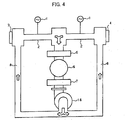
- FIG. 4 schematically shows an arrangement of a laser oscillator according to another embodiment of the present invention.
- the laser oscillator of this embodiment has the same structure as the laser oscillator shown in FIG. 2 except that a single spiral flow dust collecting mechanism 18 is provided in the circulating path of the gas medium 8 downstream of the heat exchanger 7 before the circulating path is bifurcated, instead of the two spiral flow dust collecting mechanisms 18A and 18B. Vertical cross-sections of the dust collecting mechanism 18 perpendicular to each other are shown in FIGS. 5a and 5b.
- the cylindrical body 12 is arranged horizontally such that a spiral flow of the gas medium 8 is produced around an horizontal axis of the cylindrical body 12.
- the inlet pipe 11 is arranged vertically to be connected to a left end portion of the cylindrical body 12 in FIG. 5a such that a vertical axis of the inlet pipe 11 is offset from a horizontal axis of the cylindrical body 12.
- an inner pipe 13 is arranged substantially coaxially with the cylindrical body 12 to form a spiral flow chamber 19 in the cylindrical body 12.
- the inner pipe 13 is continuously connected with an outlet pipe 14 arranged outside of the cylindrical body 12.
- the inner pipe 13 has a diameter smaller than a diameter of the cylindrical body 12 and has an inlet opening 13a at the right end thereof in FIG. 5b. Since the inner pipe 13 is arranged substantially coaxially with the cylindrical body 12, the inlet opening 13a is positioned centrally in a cross-section perpendicular to the axis of the cylindrical body 12.
- the dust chamber 17 which functions as a dust collecting section for collecting foreign matter 16 by deposition is provided below the spiral flow chamber 19.
- a slit 15 is formed at a bottom of the spiral flow chamber 19 to take the foreign matter 16 into the dust chamber 17.
- the gas medium 8 containing particulate foreign matter 16 introduced through the inlet pipe 11 spirally flows from the left-hand side to the right-hand side in the spiral flow chamber 19 around the inner pipe 13, as shown by arrows in FIGS. 5a and 5b.
- the particulate foreign matter 16 is separated from the gas medium 8 by centrifugal force to gather at a radially-peripheral portion in the spiral flow chamber 19. The gathered foreign matter 16 falls down through the slit 15 into the dust chamber 17 to be deposited.
- the slit 15 is formed between the spiral flow chamber 19 and the dust chamber 17 to extend parallel to the horizontal axis of the cylindrical body 12 and thus perpendicular to a direction of the circumferential flow of the gas medium, the gathered foreign matter 16 effectively falls down into the dust chamber 17, and the gas medium 8 does not flow into the chamber 17 even when the gas medium 8 flows at a high speed.
- the foreign matter 16 once collected and deposited in the dust chamber 17 hardly returns to the stream of the gas medium 8.
- the gas medium 8 with the foreign matter removed is introduced into the inner pipe 13 from the inlet opening 13a and fed to the outlet pipe 14 to be directed to the electric discharge section 2.
- the location of the inlet opening 13a of the inner pipe 13 near the central horizontal axis of the cylindrical body 12 is advantageous in suppressing drawing of the foreign matter 8 gathered centrifugally in the spiral flow chamber 19 into the inner pipe 13 before falling into the dust chamber 17.
- FIGS. 6a and 6b shows another example of the spiral-flow dust collecting mechanism for use in the laser oscillator shown in FIG. 4.
- a spiral-flow dust collecting mechanism 18' shown in FIGS. 6a and 6b is different from the spiral-flow dust collecting mechanism 18 shown in FIGS. 5a and 5b in arrangement of the dust chamber and the slit.
- FIGS. 6a and 6b show vertical cross-sections of the dust collecting mechanism 18' perpendicular to each other.
- the dust chamber 17 is provided laterally adjacent to the spiral flow chamber 19 at a downstream side, e.g. a right side in FIG. 6b, of the spiral flow chamber 19.
- the slit 15 is formed at an upper portion of right end of the spiral flow chamber 19 to take the foreign matter 16 into the dust chamber 17.
- the gas medium 8 containing particulate foreign matter 16 introduced through the inlet pipe 11 spirally flows from the left-hand side to the right-hand side in the spiral flow chamber 19 around the inner pipe 13, as shown by arrows in FIGS. 6a and 6b.
- the particulate foreign matter 16 is separated from the gas medium 8 by centrifugal force to gather at radially-peripheral portion in the spiral flow chamber 19.
- the spiral flow of the gas medium 8 rapidly changes its direction immediately before being introduced into the inner pipe 13.
- the gas medium 8 containing the foreign matter 16 changes its state from a state having momentum in a direction from the left-hand side to the right-hand side to a state having momentum in a direction from the right-hand side to the left-hand side.
- the foreign matter 6 since the foreign matter 6 has relative density larger than that of the gas medium 8 and thus larger inertia, most of the foreign matter 6 is separated from the gas medium 8 and introduced into the dust chamber 17 to be deposited through the slit 15.
- the slit 15 is formed at a radially-peripheral position between the spiral flow chamber 19 and the dust chamber 17 to extend radially of the cylindrical body 12, and thus substantially perpendicular to a direction of the circumferential flow of the gas medium, the gathered foreign matter 16 is effectively taken into the dust chamber 17, and the gas medium 8 does not flow into the chamber 17 even when the gas medium 8 flows at a high speed.
- the foreign matter 16 once collected and deposited in the dust chamber 17 hardly returns to the stream of the gas medium 8.
- the gas medium 8 with the foreign matter removed is introduced into the inner pipe 13 from the inlet opening 13a and fed to the outlet pipe 14 to be directed to the electric discharge section 2.
- the location of the inlet opening 13a of the inner pipe 13 around the central horizontal axis of the cylindrical body 12 is advantageous in suppressing drawing of the foreign matter 8 gathered centrifugally in the spiral flow chamber 19 into the inner pipe 13 before taken into the dust chamber 17.
- the blower 6 has a function of adjusting a blowing pressure of the gas medium (e.g. adjustment by a pressure adjusting dial, manual operation of keys on a control panel). It is preferable to adjust the blowing pressure of the gas medium in view of diameter and/or mass of the foreign matter to be separated and collected for removal. The adjustment may be performed while the laser oscillator is stopped, e.g. before a start of operation.
- the blowing pressure of the gas medium is set higher, the flow speed of the gas medium is made high to effectively separate a heavy foreign matter or a foreign matter having relatively large diameter.
- the blowing pressure of the gas medium is set lower to make the flow speed of the gas medium low. Therefore, a plurality of grades, e.g. three grades of blowing pressure are set in advance, and the gas medium is circulated at respective grades of blowing pressure at respective predetermined time periods without laser oscillation, to effectively remove the foreign matter of various diameters and masses from the gas medium.
- particulate foreign matter such as dust contained in gas medium is effectively removed and collected from the gas medium by providing a spiral flow path through which the gas medium flows spirally in a circulating path of the gas medium of a laser oscillator.
- the particulate foreign matter which may be caught by optical components such as mirrors of the laser oscillator, is greatly reduced in the laser oscillator, so that reduction of output power of the laser oscillator and damage of the optical components are prevented or reduced, to provide a laser oscillator of high reliability and requiring less maintenance or cleaning of the optical components.
Landscapes
- Physics & Mathematics (AREA)
- Electromagnetism (AREA)
- Engineering & Computer Science (AREA)
- Plasma & Fusion (AREA)
- Optics & Photonics (AREA)
- Lasers (AREA)
Abstract
Description
Claims (9)
- A laser oscillator having a circulating path for circulating gas laser medium subjected to laser pumping, comprising:a spiral flow section provided in the circulating path for producing a spiral flow of the gas laser medium to separate particulate foreign matter contained in the gas medium by centrifugal force generated in the spiral flow; anda dust collecting section arranged in the vicinity of said spiral flow section for collecting the separated particulate foreign matter by deposition.
- A laser oscillator according to claim 1, further comprising an adjuster for adjusting pressure of the gas laser medium flowing in the circulating path in accordance with diameter and/or mass of the particulate foreign matter to be separated and collected.
- A laser oscillator according to claim 1 or 2, wherein said spiral flow section includes a cylindrical body and an inner pipe arranged substantially coaxially with the cylindrical body, to produce the spiral flow of the gas laser medium.
- A laser oscillator according to claim 3, wherein said inner pipe has an inlet opening to introduce the gas laser medium centrally in a cross-section perpendicular to an axis of the cylindrical body at an end portion of said spiral flow section.
- A laser oscillator according to any of claims 1 to 4, wherein said dust collecting section is arranged below the spiral flow section.
- A laser oscillator according to any of claims 1 to 4, wherein said dust collectirg section is arranged laterally adjacent to the spiral flow section.
- A laser oscillator according to any preceding claim, wherein a slit is formed between said spiral flow section and said dust collecting section, to take the separated particulate foreign matter into said dust collecting section.
- A laser oscillator according to claim 7, wherein said slit is formed at a peripheral position in the spiral flow section.
- A laser oscillator according to claim 7 or 8, wherein said slit is formed to extend substantially perpendicular to the spiral flow of the gas laser medium in the spiral flow section.
Applications Claiming Priority (2)
| Application Number | Priority Date | Filing Date | Title |
|---|---|---|---|
| JP2002081757A JP3721337B2 (en) | 2002-03-22 | 2002-03-22 | Laser oscillator |
| JP2002081757 | 2002-03-22 |
Publications (3)
| Publication Number | Publication Date |
|---|---|
| EP1347543A2 true EP1347543A2 (en) | 2003-09-24 |
| EP1347543A3 EP1347543A3 (en) | 2005-04-27 |
| EP1347543B1 EP1347543B1 (en) | 2006-11-08 |
Family
ID=27785371
Family Applications (1)
| Application Number | Title | Priority Date | Filing Date |
|---|---|---|---|
| EP03251532A Expired - Lifetime EP1347543B1 (en) | 2002-03-22 | 2003-03-13 | Laser oscillator |
Country Status (4)
| Country | Link |
|---|---|
| US (1) | US6826221B2 (en) |
| EP (1) | EP1347543B1 (en) |
| JP (1) | JP3721337B2 (en) |
| DE (1) | DE60309528T2 (en) |
Cited By (1)
| Publication number | Priority date | Publication date | Assignee | Title |
|---|---|---|---|---|
| CN110927031A (en) * | 2018-09-20 | 2020-03-27 | 现代自动车株式会社 | Particulate Sensing Sensor Assembly |
Families Citing this family (9)
| Publication number | Priority date | Publication date | Assignee | Title |
|---|---|---|---|---|
| JP2005123448A (en) * | 2003-10-17 | 2005-05-12 | Fanuc Ltd | Turbo blower for laser oscillator |
| CN100438234C (en) * | 2006-03-21 | 2008-11-26 | 李再光 | Gas cooling cathode insulation box of gas laser and its laser |
| JP4137961B2 (en) | 2006-07-13 | 2008-08-20 | ファナック株式会社 | Gas laser oscillator |
| JP2010123665A (en) * | 2008-11-18 | 2010-06-03 | Shibuya Kogyo Co Ltd | Gas laser oscillator, and laser processing machine including the same |
| JP4782887B1 (en) * | 2010-04-02 | 2011-09-28 | ファナック株式会社 | Gas laser device |
| JP5790040B2 (en) * | 2011-03-11 | 2015-10-07 | ソニー株式会社 | Illumination device and display device |
| DE102012205870B3 (en) * | 2012-04-11 | 2013-02-21 | Trumpf Laser- Und Systemtechnik Gmbh | Cooling arrangement for cooling of laser gas for gas laser system, has secondary cooling circuit with supplementary heat exchanger that is located for additional cooling of laser gas flowing from fan to resonator |
| JP6254983B2 (en) | 2015-09-15 | 2017-12-27 | ファナック株式会社 | Laser oscillator including a heat exchanger having a function of collecting foreign matter |
| EP4574233A1 (en) | 2023-12-21 | 2025-06-25 | ASML Netherlands B.V. | Optical amplifier and components therefor |
Family Cites Families (6)
| Publication number | Priority date | Publication date | Assignee | Title |
|---|---|---|---|---|
| DE2618357A1 (en) * | 1976-04-27 | 1977-11-17 | Messerschmitt Boelkow Blohm | GAS DYNAMIC CO DEEP 2 LASER |
| DE3323954A1 (en) * | 1983-07-02 | 1985-01-10 | Messer Griesheim Gmbh, 6000 Frankfurt | GAS LASER, IN PARTICULAR FAST-FLOWING AXIAL CURRENT GAS TRANSPORT LASER |
| JPS63133585A (en) * | 1986-11-25 | 1988-06-06 | Matsushita Electric Ind Co Ltd | Gas pressure stabilizing equipment for gas laser device and the like |
| JP2593156B2 (en) * | 1987-07-07 | 1997-03-26 | ファナック株式会社 | Gas laser device |
| US4787091A (en) * | 1987-07-13 | 1988-11-22 | Rockwell International Corporation | Chemical laser system employing iodine atoms as a lasing gas |
| US5537326A (en) * | 1994-09-12 | 1996-07-16 | Fish; Randall C. | System for manufacturing parts for a functional device such as a cyclone |
-
2002
- 2002-03-22 JP JP2002081757A patent/JP3721337B2/en not_active Expired - Fee Related
-
2003
- 2003-03-12 US US10/385,529 patent/US6826221B2/en not_active Expired - Lifetime
- 2003-03-13 DE DE60309528T patent/DE60309528T2/en not_active Expired - Lifetime
- 2003-03-13 EP EP03251532A patent/EP1347543B1/en not_active Expired - Lifetime
Cited By (1)
| Publication number | Priority date | Publication date | Assignee | Title |
|---|---|---|---|---|
| CN110927031A (en) * | 2018-09-20 | 2020-03-27 | 现代自动车株式会社 | Particulate Sensing Sensor Assembly |
Also Published As
| Publication number | Publication date |
|---|---|
| US20030179797A1 (en) | 2003-09-25 |
| JP2003283008A (en) | 2003-10-03 |
| EP1347543B1 (en) | 2006-11-08 |
| DE60309528T2 (en) | 2007-02-15 |
| US6826221B2 (en) | 2004-11-30 |
| JP3721337B2 (en) | 2005-11-30 |
| EP1347543A3 (en) | 2005-04-27 |
| DE60309528D1 (en) | 2006-12-21 |
Similar Documents
| Publication | Publication Date | Title |
|---|---|---|
| US6826221B2 (en) | Laser oscillator | |
| EP3437712A1 (en) | Dust collection method, dust collection device, and laser processing machine | |
| CN105284193B (en) | Produced using the high yield particle of plasma system | |
| EP1284803A1 (en) | Separator with multiple function vanes for a vacuum cleaner apparatus | |
| CN118513692B (en) | Multi-section type laser cutting device for medal production and cutting process thereof | |
| KR102304128B1 (en) | Concentrated dedusting filter dust collector capable of removing nanoparticle-grade fine dust and method thereof | |
| US20170077666A1 (en) | Laser oscillator comprising heat exchanger having function of collecting foreign matters | |
| US8792529B2 (en) | Gas laser oscillation device and gas laser processing machine | |
| CN114762950A (en) | Air circulation system and fine polishing apparatus including the same | |
| EP1634635A1 (en) | Mist removing apparatus and mist removing method | |
| US20050083985A1 (en) | Turbo-blower for laser medium gas | |
| JPH06101597B2 (en) | Gas transport laser device with axial gas flow | |
| JP6454877B2 (en) | Gas laser oscillator | |
| CN103124049A (en) | Switch cabinet for textile machine | |
| CN108161561A (en) | Chip removal liquid feed device and method | |
| EP0829932B1 (en) | Blower for a gas laser | |
| CN118401288A (en) | Separators for fluid cleaning devices | |
| JPH02288385A (en) | Gas laser device | |
| EP4018487A1 (en) | Wafer optical processing device and sintering furnace | |
| JPH06291390A (en) | Gas laser equipment | |
| CN222818474U (en) | A filtering device for cutting fluid used in CNC machine tools | |
| CN221328313U (en) | Excimer laser | |
| CN223185724U (en) | An active cooling system for laser tubes of laser machine tools | |
| CN111331253B (en) | Material cleaning device and laser cutting system | |
| JPH05251792A (en) | Discharge excitation type laser device |
Legal Events
| Date | Code | Title | Description |
|---|---|---|---|
| PUAI | Public reference made under article 153(3) epc to a published international application that has entered the european phase |
Free format text: ORIGINAL CODE: 0009012 |
|
| AK | Designated contracting states |
Kind code of ref document: A2 Designated state(s): AT BE BG CH CY CZ DE DK EE ES FI FR GB GR HU IE IT LI LU MC NL PT RO SE SI SK TR |
|
| AX | Request for extension of the european patent |
Extension state: AL LT LV MK |
|
| PUAL | Search report despatched |
Free format text: ORIGINAL CODE: 0009013 |
|
| RIC1 | Information provided on ipc code assigned before grant |
Ipc: 7H 01S 3/03 B Ipc: 7H 01S 3/036 A |
|
| AK | Designated contracting states |
Kind code of ref document: A3 Designated state(s): AT BE BG CH CY CZ DE DK EE ES FI FR GB GR HU IE IT LI LU MC NL PT RO SE SI SK TR |
|
| AX | Request for extension of the european patent |
Extension state: AL LT LV MK |
|
| 17P | Request for examination filed |
Effective date: 20050803 |
|
| AKX | Designation fees paid |
Designated state(s): DE |
|
| RIC1 | Information provided on ipc code assigned before grant |
Ipc: H01S 3/03 20060101AFI20060314BHEP |
|
| GRAP | Despatch of communication of intention to grant a patent |
Free format text: ORIGINAL CODE: EPIDOSNIGR1 |
|
| RIN1 | Information on inventor provided before grant (corrected) |
Inventor name: MAEDA, MICHINORI Inventor name: MIYAKE, AKIRA Inventor name: EGAWA, AKIRA Inventor name: OHTA, KAZUYA |
|
| GRAS | Grant fee paid |
Free format text: ORIGINAL CODE: EPIDOSNIGR3 |
|
| GRAA | (expected) grant |
Free format text: ORIGINAL CODE: 0009210 |
|
| AK | Designated contracting states |
Kind code of ref document: B1 Designated state(s): DE |
|
| REF | Corresponds to: |
Ref document number: 60309528 Country of ref document: DE Date of ref document: 20061221 Kind code of ref document: P |
|
| PLBE | No opposition filed within time limit |
Free format text: ORIGINAL CODE: 0009261 |
|
| STAA | Information on the status of an ep patent application or granted ep patent |
Free format text: STATUS: NO OPPOSITION FILED WITHIN TIME LIMIT |
|
| 26N | No opposition filed |
Effective date: 20070809 |
|
| PGFP | Annual fee paid to national office [announced via postgrant information from national office to epo] |
Ref country code: DE Payment date: 20200303 Year of fee payment: 18 |
|
| REG | Reference to a national code |
Ref country code: DE Ref legal event code: R082 Ref document number: 60309528 Country of ref document: DE Representative=s name: HL KEMPNER PATENTANWALT, RECHTSANWALT, SOLICIT, DE |
|
| REG | Reference to a national code |
Ref country code: DE Ref legal event code: R119 Ref document number: 60309528 Country of ref document: DE |
|
| PG25 | Lapsed in a contracting state [announced via postgrant information from national office to epo] |
Ref country code: DE Free format text: LAPSE BECAUSE OF NON-PAYMENT OF DUE FEES Effective date: 20211001 |