EP1347484A1 - Disjoncteur haute tension comprenant un clapet de décompression d'une chambre de soufflage thermique - Google Patents
Disjoncteur haute tension comprenant un clapet de décompression d'une chambre de soufflage thermique Download PDFInfo
- Publication number
- EP1347484A1 EP1347484A1 EP03290612A EP03290612A EP1347484A1 EP 1347484 A1 EP1347484 A1 EP 1347484A1 EP 03290612 A EP03290612 A EP 03290612A EP 03290612 A EP03290612 A EP 03290612A EP 1347484 A1 EP1347484 A1 EP 1347484A1
- Authority
- EP
- European Patent Office
- Prior art keywords
- nozzle
- circuit breaker
- chamber
- thermal
- valve
- Prior art date
- Legal status (The legal status is an assumption and is not a legal conclusion. Google has not performed a legal analysis and makes no representation as to the accuracy of the status listed.)
- Granted
Links
- 230000006837 decompression Effects 0.000 title 1
- 238000007664 blowing Methods 0.000 claims description 51
- 230000006835 compression Effects 0.000 claims description 14
- 238000007906 compression Methods 0.000 claims description 14
- 238000007599 discharging Methods 0.000 claims description 2
- 239000007789 gas Substances 0.000 description 42
- 238000010891 electric arc Methods 0.000 description 6
- 238000006073 displacement reaction Methods 0.000 description 3
- 238000010276 construction Methods 0.000 description 2
- 238000010438 heat treatment Methods 0.000 description 2
- 239000000203 mixture Substances 0.000 description 2
- 230000008929 regeneration Effects 0.000 description 2
- 238000011069 regeneration method Methods 0.000 description 2
- 238000000926 separation method Methods 0.000 description 2
- 239000004809 Teflon Substances 0.000 description 1
- 229920006362 Teflon® Polymers 0.000 description 1
- 230000008033 biological extinction Effects 0.000 description 1
- 230000000295 complement effect Effects 0.000 description 1
- 230000007423 decrease Effects 0.000 description 1
- 230000018109 developmental process Effects 0.000 description 1
- 239000003989 dielectric material Substances 0.000 description 1
- 239000011810 insulating material Substances 0.000 description 1
- 238000004519 manufacturing process Methods 0.000 description 1
- 239000000463 material Substances 0.000 description 1
- 238000012986 modification Methods 0.000 description 1
- 230000004048 modification Effects 0.000 description 1
- 238000000465 moulding Methods 0.000 description 1
- 238000005192 partition Methods 0.000 description 1
- 230000036967 uncompetitive effect Effects 0.000 description 1
- 238000011144 upstream manufacturing Methods 0.000 description 1
Images


Classifications
-
- H—ELECTRICITY
- H01—ELECTRIC ELEMENTS
- H01H—ELECTRIC SWITCHES; RELAYS; SELECTORS; EMERGENCY PROTECTIVE DEVICES
- H01H33/00—High-tension or heavy-current switches with arc-extinguishing or arc-preventing means
- H01H33/70—Switches with separate means for directing, obtaining, or increasing flow of arc-extinguishing fluid
- H01H33/88—Switches with separate means for directing, obtaining, or increasing flow of arc-extinguishing fluid the flow of arc-extinguishing fluid being produced or increased by movement of pistons or other pressure-producing parts
- H01H33/90—Switches with separate means for directing, obtaining, or increasing flow of arc-extinguishing fluid the flow of arc-extinguishing fluid being produced or increased by movement of pistons or other pressure-producing parts this movement being effected by or in conjunction with the contact-operating mechanism
- H01H33/901—Switches with separate means for directing, obtaining, or increasing flow of arc-extinguishing fluid the flow of arc-extinguishing fluid being produced or increased by movement of pistons or other pressure-producing parts this movement being effected by or in conjunction with the contact-operating mechanism making use of the energy of the arc or an auxiliary arc
-
- H—ELECTRICITY
- H01—ELECTRIC ELEMENTS
- H01H—ELECTRIC SWITCHES; RELAYS; SELECTORS; EMERGENCY PROTECTIVE DEVICES
- H01H33/00—High-tension or heavy-current switches with arc-extinguishing or arc-preventing means
- H01H33/70—Switches with separate means for directing, obtaining, or increasing flow of arc-extinguishing fluid
- H01H33/88—Switches with separate means for directing, obtaining, or increasing flow of arc-extinguishing fluid the flow of arc-extinguishing fluid being produced or increased by movement of pistons or other pressure-producing parts
- H01H33/90—Switches with separate means for directing, obtaining, or increasing flow of arc-extinguishing fluid the flow of arc-extinguishing fluid being produced or increased by movement of pistons or other pressure-producing parts this movement being effected by or in conjunction with the contact-operating mechanism
- H01H2033/906—Switches with separate means for directing, obtaining, or increasing flow of arc-extinguishing fluid the flow of arc-extinguishing fluid being produced or increased by movement of pistons or other pressure-producing parts this movement being effected by or in conjunction with the contact-operating mechanism with pressure limitation in the compression volume, e.g. by valves or bleeder openings
-
- H—ELECTRICITY
- H01—ELECTRIC ELEMENTS
- H01H—ELECTRIC SWITCHES; RELAYS; SELECTORS; EMERGENCY PROTECTIVE DEVICES
- H01H33/00—High-tension or heavy-current switches with arc-extinguishing or arc-preventing means
- H01H33/70—Switches with separate means for directing, obtaining, or increasing flow of arc-extinguishing fluid
- H01H33/88—Switches with separate means for directing, obtaining, or increasing flow of arc-extinguishing fluid the flow of arc-extinguishing fluid being produced or increased by movement of pistons or other pressure-producing parts
- H01H33/90—Switches with separate means for directing, obtaining, or increasing flow of arc-extinguishing fluid the flow of arc-extinguishing fluid being produced or increased by movement of pistons or other pressure-producing parts this movement being effected by or in conjunction with the contact-operating mechanism
- H01H2033/908—Switches with separate means for directing, obtaining, or increasing flow of arc-extinguishing fluid the flow of arc-extinguishing fluid being produced or increased by movement of pistons or other pressure-producing parts this movement being effected by or in conjunction with the contact-operating mechanism using valves for regulating communication between, e.g. arc space, hot volume, compression volume, surrounding volume
-
- H—ELECTRICITY
- H01—ELECTRIC ELEMENTS
- H01H—ELECTRIC SWITCHES; RELAYS; SELECTORS; EMERGENCY PROTECTIVE DEVICES
- H01H33/00—High-tension or heavy-current switches with arc-extinguishing or arc-preventing means
- H01H33/70—Switches with separate means for directing, obtaining, or increasing flow of arc-extinguishing fluid
- H01H33/7015—Switches with separate means for directing, obtaining, or increasing flow of arc-extinguishing fluid characterised by flow directing elements associated with contacts
- H01H33/7023—Switches with separate means for directing, obtaining, or increasing flow of arc-extinguishing fluid characterised by flow directing elements associated with contacts characterised by an insulating tubular gas flow enhancing nozzle
Definitions
- the invention relates to a circuit breaker comprising two contacts arranged in a breaking space containing a dielectric gas and between which an electric arc is established during a circuit breaker opening operation, said circuit breaker including a thermal blowing chamber communicating with the breaking space.
- the invention applies to a high voltage circuit breaker intended to cut strong currents by limiting as much as possible the duration of appearance of an arc between its contacts during the opening operation.
- a strong current here denotes a current of high intensity, or else a current which is established for a long time.
- the invention applies in particular to breaking of low frequency alternating currents such as for example the currents flowing in the railway supply networks, for example in Germany and Switzerland, which are supplied at a frequency of 16.66 Hz or 25 Hz. With this type of frequency, the duration of the current is two or three times longer than for a frequency of 50 Hz, so that if an electric arc occurs, the heat produced can be two or three times greater than for a 50 Hz current.
- conventional circuit breakers usually include a pneumatic self-blowing device producing a dielectric gas blowing in the direction of the arc during the opening in order to favor the cutting of this arc.
- a device self-blowing conventionally includes a compression chamber including a piston linked in movement to a movable contact of the circuit breaker and allowing a constant volume of fresh gas to be blown towards the breaking space during each opening. The piston is moved in using the energy of the circuit breaker control which produces the displacement of the moving contact during opening.
- the pneumatic blowing produced must be all the more important as the electric arc has a high intensity.
- One way to increase the blowing for cutting strong arcs intensity consists in adding to the compression blowing chamber pneumatic a thermal blowing chamber.
- the dielectric gas is heated by the electric arc and sees its pressure increase.
- Room is shaped to promote the flow of the gas it contains towards the breaking space in the event of an increase in the pressure of this gas, so that it produces a blowing all the more important as the intensity of the arc is high.
- the temperature can rise too much in the room thermal, which brings down the dielectric strength of the gas which is blown into the breaking space and makes it impossible to cut the current.
- circuit breaker comprising a thermal blowing chamber which communicates part with a cut-off space through the neck of a nozzle and secondly with an expansion space through conduits closed by valves.
- at least one valve is a discharge valve able to open when the pressure in the chamber thermal is above a certain threshold to evacuate the gas under pressure out of the chamber to the expansion space.
- the breaking capacity is improved because if the pressure becomes too high in the thermal chamber, the valve opens to depressurize the room. This depressurization decreases the temperature, which ensures that the gas blown into the cutting space has satisfactory dielectric strength.
- a circuit breaker with respectively pneumatic blowing chambers and is known from patent document EP 0296363.
- the wall of separation between these two chambers is spring mounted, and includes a light which is arranged with another light arranged in the cylindrical envelope which delimits the periphery of the blowing chamber pneumatic, so that these two lights constitute a valve evacuation of overpressure gases from the blowing chamber thermal.
- This partition wall is able to compress the spring if the pressure in the thermal blowing chamber is greater than that in the pneumatic blowing chamber, allowing to place the lights facing each other to let the overpressure gases escape to a space of expansion which surrounds the cylindrical envelope common to the chambers of pneumatic and thermal blowing.
- a circuit breaker architecture in which permanent current contacts would be arranged around the blowing, i.e. in the hot gas expansion space overpressure.
- the gas between the permanent current contacts at moment of separation of the arcing contacts would no longer have properties sufficient dielectrics to prevent arcing between these permanent current contacts, which are not intended to hold a bow.
- An object of the invention is to remedy these drawbacks by proposing a circuit breaker capable of breaking high currents thanks to a system evacuation of hot gases under overpressure, without this requiring too significant modifications to the architecture of a conventional circuit breaker.
- a device is sought which makes it possible not to have to modify that a very limited number of parts on a conventional circuit breaker not provided to support currents with wavelengths / periods too long (or such low frequencies).
- the invention relates to a circuit breaker comprising two contacts arranged in a breaking space which is delimited by a nozzle which contains a dielectric gas, further including a thermal blowing chamber which communicates on the one hand with said cutting space through a neck of said nozzle and on the other hand with a expansion space through a discharge pipe closed by a valve, said valve opening when the pressure in the thermal chamber is greater than a certain threshold for discharging the pressurized gas out of the chamber, characterized in that said discharge duct is produced in said nozzle and defines a shape of revolution in the thickness of the nozzle according to the general shape thereof, to lead into said space expansion downstream of said cutting space with respect to said neck.
- gas blowing through the channel contributes to the blowing of hot gases contained in the diverges from the nozzle and therefore improves the regeneration of the holding dielectric in the breaking space after extinction of the arc.
- this nozzle may also incorporate the valve, so that it could be adapted to an existing circuit breaker in order to reduce the development and manufacturing costs.
- the nozzle is consisting of two coaxial parts, an external part surrounding a part internal so as to leave a free space for revolution forming a conduit evacuation of gases from the thermal chamber, the valve being designed to close said exhaust duct.
- the valve can be manufactured at lower cost.
- the valve and an exhaust duct partner defining a form of revolution reduce losses dump.
- the valve may have a shape annular while being mounted in abutment on one or more calibrated springs for open against the action of these springs. The valve opening threshold can thus be adjusted by simply changing the calibrated spring or springs.
- the circuit breaker includes a piston compression chamber which communicates with the thermal compression chamber.
- the gas blown into the breaking space is a mixture of the gas fresh from the piston compression chamber and gas more hot from the thermal chamber which lowers its temperature to maintain a high breaking capacity of the circuit breaker.
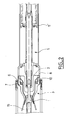
- FIG. 1 schematically shows an example of a circuit breaker according to the invention in axial section.
- This circuit breaker includes a fixed contact 1 forming a rod and a movable contact 2 which is moved in a direction axial AX.
- the movable contact 2 is hollow and is part of a movable assembly including a blowing nozzle 3 of revolution, coaxial with the axis AX, a thermal blowing chamber 4 and a compression chamber by piston 5.
- the moving element also includes a permanent contact 6 which cooperates in closing the circuit breaker with another permanent contact 7 substantially cylindrical which is fixed.
- the blowing nozzle 3 which is made with an insulating material such as Teflon includes a 3 'neck of small section which widens to form a divergent 3 "downstream of this neck.
- contact 1 crosses the neck 3 'of the nozzle 3 and enters the hollow contact 2 located at upstream of the neck along the axis AX, as visible in Figures 1 and 2.
- the neck and the divergence of the nozzle 3 define here the cutting space of an arc electric that stretches between contacts 1 and 2 during the opening of the circuit breaker visible in Figures 3 and 4.
- This breaking space communicates with the thermal blowing chamber 4 via a 4 ′ revolution-shaped duct located between the blowing chamber thermal 4 and the breaking space.
- the thermal blowing chamber 4 defines a coaxial annular space to the axis AX, delimited by the movable contact 2 and by a casing 8 surrounding the movable contact 2, the casing 8 being closed at one of its ends by the blowing nozzle 3.
- the dielectric gas contained in the thermal blowing 4 is put under overpressure by heating on contact of the electric arc which is established between contacts 1 and 2 when the opening. As known from the state of the art, this overpressure produces the thermal blowing of the dielectric gas which moves from the chamber thermal 4 towards the breaking space.
- This blowing chamber thermal 4 communicates with the piston compression chamber 5 at through a plurality of channels 9. When the circuit breaker opens, the gas dielectric contained in the chamber 5 is compressed to flow at through the thermal chamber 4 in the breaking space. Simultaneously with blowing produced by the compression chamber 5, the heating due to the arc electric increases the pressure in the thermal chamber to increase the flow of dielectric gas in the breaking space, as shown more high.
- the thermal chamber 4 communicates through a discharge duct 10 'closed by a valve 10 to an expansion space 15.
- This space expansion is located downstream of the cutting space with respect to the 3 'neck of nozzle, and is partly bounded by the 3 "divergent nozzle.
- the valve opens when the pressure in the thermal chamber 4 is greater than one certain threshold, to evacuate the pressurized gas out of the chamber thermal 4 ..
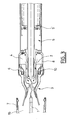
- the arc electric increases the pressure in the thermal chamber without this pressure does not exceed a predetermined threshold, so that the valve remains closed, as shown in figure 3.
- valve 10 opens to drop the pressure in the thermal chamber, as shown in Figure 4. This drop in pressure is accompanied by a temperature drop, which ensures that the dielectric gas blown into the breaking space has a satisfactory insulating power.
- This valve can for example be mounted at the casing 8 to directly evacuate the gas overpressure to the outside of the thermal blowing chamber 4.
- the valve 10 can be integrated into the blowing nozzle 3 which covers the casing 8.
- the valve 10 here has an annular shape so that it can be mounted in the nozzle 3 on the side of the thermal blowing chamber 4.
- This valve which is made of a rigid material is mounted in a housing 11 of the nozzle defining an annular groove being compressed by one or more calibrated springs 12 which press on the bottom of the groove 11. The valve is thus able to move in translation along the axis AX to open against the action of the springs 12.
- An annular seal 13 seals between the external surface of the valve and the groove.
- This valve is powered by through a plurality of supply conduits 14 made in the nozzle area 3 leading directly to the thermal chamber for have a large opening surface.
- the bottom of the groove 11 communicates with the divergent 3 "by through a discharge duct 10 'located in the thickness of the nozzle.
- This exhaust duct 10 'communicating the housing 11 with the expansion space 15 defines a shape of revolution in the thickness of the nozzle 3 and according to the general shape thereof. It is located in the extension of the valve 10 downstream of its housing 11 so as to be open or closed by the valve.
- the implementation of a valve and a conduit each defining a form of revolution in the nozzle makes it possible to form a flow circuit of large section, that is to say introducing low pressure drops.
- a large flow of gas can be evacuated to drop pressure as quickly as possible and the temperature in the thermal blowing chamber during shutdown high intensity electric arcs.
- This blowing nozzle can be produced by molding and include a cover covering the housing 11 on the side of the thermal blowing chamber while allowing the valve to communicate with this chamber to allow the evacuation of overpressure gas.
- the evacuation duct 10 ′ opens into the divergent 3 "from the nozzle and thus contributes to the regeneration of the gas downstream from the neck nozzle 3 ', which improves the dielectric strength of the gas between the arcing contacts 1 and 2 during the dielectric phase of the breaking.
- the nozzle 3 comprises an internal part 3B and an external part 3A which are coaxial. More specifically, the outer surface of one end of this internal part 3B has on the whole a flared shape. The part of larger diameter of this end is inserted into the casing 8, by example by screwing, and has substantially the shape of an annular flange in which are pierced with the supply conduits 14.
- the external part 3A of the nozzle 3 has a shaped end cylindrical annular with the same external diameter as the annular flange of the internal part 3B, and is inserted into the casing 8 for example by screwing this annular end to bear against the flange ring of the internal part 3B.
- part 3A surrounds all part 3B with the exception of the annular flange of the latter.
- Nozzle 3 can be assembled by mounting the internal part 3B then the external part 3A in the casing 8 before screwing the permanent contact 6 which forms a ring around the casing 8 capable of holding the two nozzle parts 3A and 3B in position relative to the housing 8. After mounting these two nozzle parts, a part of complementary nozzle 3C located in the extension of the internal part 3B at the divergent 3 "can be screwed or even glued on the internal part 3B so as to extend the evacuation channel 10 'towards expansion space 15.
- the compression by piston 5 communicates directly with the thermal blowing 4 through channels 9 provided with non-return valves 9 ′, so that the gases blown into the breaking space are a mixture fresh gas from the piston compression chamber 5 and gas hot from the thermal blowing chamber 4.
- the temperature of the dielectric gas is lowered by the presence of fresh gas, which further increases the breaking capacity of the circuit breaker according to the invention.
- the piston 5 'of the compression chamber 5 can be mounted on a spring.
- the spring is arranged to compress during the movement maneuver when opening the movable contact, so that it releases after displacement of the contact mobile.
Landscapes
- Circuit Breakers (AREA)
- Emergency Protection Circuit Devices (AREA)
Abstract
Description
Claims (6)
- Disjoncteur comprenant deux contacts (1, 2) disposés dans un espace de coupure qui est délimité par une buse (3) de soufflage et qui contient un gaz diélectrique, incluant une chambre de soufflage thermique (4) qui communique d'une part avec ledit espace de coupure à travers un col (3') de ladite buse et d'autre part avec un espace d'expansion (15) à travers un conduit d'évacuation (10') fermé par un clapet (10), ledit clapet s'ouvrant quand la pression dans la chambre thermique (4) est supérieure à un certain seuil pour évacuer le gaz sous pression hors de la chambre, caractérisé en ce que ledit conduit d'évacuation (10') est réalisé dans ladite buse (3) et définit une forme de révolution dans l'épaisseur de la buse suivant la forme générale de celle-ci, pour déboucher dans ledit espace d'expansion (15) en aval dudit espace de coupure par rapport audit col (3').
- Disjoncteur selon la revendication 1, dans lequel la section de ladite buse (3) s'élargit pour former un divergent (3") qui délimite en partie ledit espace d'expansion (15) en aval dudit col (3'), ledit conduit d'évacuation (10') débouchant dans ce divergent (3").
- Disjoncteur selon l'une des revendications 1 et 2, dans lequel ladite buse (3) est constituée de deux parties (3A, 3B) coaxiales, une partie externe (3A) entourant une partie interne (3B) de manière à laisser un espace libre de révolution formant le conduit d'évacuation (10') des gaz hors de la chambre de soufflage thermique (4).
- Disjoncteur selon l'une des revendications 1 à 3, dans lequel ledit clapet (10) est incorporé dans ladite buse (3) et a une forme annulaire pour fermer le conduit d'évacuation (10'), ce clapet s'ouvrant contre l'action d'au moins un ressort (12) calibré.
- Disjoncteur selon l'une des revendications 1 à 4, comprenant une chambre de compression pneumatique par piston (5) qui communique avec ladite chambre de soufflage thermique (4).
- Réseau d'alimentation électrique haute tension de fréquence assignée inférieure ou égale à 25 Hz, incluant un disjoncteur selon l'une des revendications 1 à 5.
Applications Claiming Priority (2)
| Application Number | Priority Date | Filing Date | Title |
|---|---|---|---|
| FR0203305 | 2002-03-18 | ||
| FR0203305A FR2837321B1 (fr) | 2002-03-18 | 2002-03-18 | Disjoncteur haute tension comprenant un clapet de decompression |
Publications (2)
| Publication Number | Publication Date |
|---|---|
| EP1347484A1 true EP1347484A1 (fr) | 2003-09-24 |
| EP1347484B1 EP1347484B1 (fr) | 2006-05-31 |
Family
ID=27772199
Family Applications (1)
| Application Number | Title | Priority Date | Filing Date |
|---|---|---|---|
| EP03290612A Expired - Lifetime EP1347484B1 (fr) | 2002-03-18 | 2003-03-12 | Disjoncteur haute tension comprenant un clapet de décompression d'une chambre de soufflage thermique |
Country Status (7)
| Country | Link |
|---|---|
| US (1) | US6744001B2 (fr) |
| EP (1) | EP1347484B1 (fr) |
| JP (1) | JP2003272493A (fr) |
| CN (1) | CN1445807A (fr) |
| AT (1) | ATE328358T1 (fr) |
| DE (1) | DE60305552T2 (fr) |
| FR (1) | FR2837321B1 (fr) |
Cited By (2)
| Publication number | Priority date | Publication date | Assignee | Title |
|---|---|---|---|---|
| EP2237300A1 (fr) * | 2009-04-03 | 2010-10-06 | Areva T&D Sas | Chambre de coupure de courant à contact mobile à soufflage d'arc réalisé intégralement par l'intérieur de celui-ci, interrupteur by pass HVDC et sous station de conversion HVDC comprenant une telle chambre |
| EP4415017A1 (fr) * | 2023-02-07 | 2024-08-14 | General Electric Technology GmbH | Disjoncteur comportant une gestion améliorée du flux gazeux |
Families Citing this family (17)
| Publication number | Priority date | Publication date | Assignee | Title |
|---|---|---|---|---|
| ATE458259T1 (de) | 2005-09-26 | 2010-03-15 | Abb Technology Ag | Hochspannungsschalter mit verbesserter schaltleistung |
| US20070119819A1 (en) * | 2005-11-30 | 2007-05-31 | Thangavelu Asokan | Axial current interrupter |
| CN101000837B (zh) * | 2006-01-13 | 2010-06-09 | 河南平高电气股份有限公司 | 一种高压断路器 |
| US20070241079A1 (en) * | 2006-04-13 | 2007-10-18 | Johnson David S | High voltage circuit breaker with re-fill valve |
| DE102006019383A1 (de) * | 2006-04-24 | 2007-10-25 | Siemens Ag | Unterbrechereinheit eines elektrischen Schaltgerätes |
| ATE523889T1 (de) | 2006-11-27 | 2011-09-15 | Abb Technology Ag | Puffer leistungsschalter mit reduziertem puffervolumendruck |
| EP1939910A1 (fr) * | 2006-12-27 | 2008-07-02 | ABB Technology AG | Disjoncteur à gaz comprimé avec une aperture radiale du passage |
| US20090179010A1 (en) * | 2008-01-10 | 2009-07-16 | Thangavelu Asokan | Ablative-based current interrupter |
| US7875822B2 (en) * | 2008-01-10 | 2011-01-25 | General Electric Company | Ablative-based multiphase current interrupter |
| US8063333B2 (en) * | 2008-02-05 | 2011-11-22 | Southern States, Inc. | Limited flash-over electric power switch |
| FR2937179A1 (fr) * | 2008-10-09 | 2010-04-16 | Areva T & D Sa | Chambre de coupure pour disjoncteur haute tension a soufflage d'arc ameliore |
| DE102010020979A1 (de) * | 2010-05-12 | 2011-11-17 | Siemens Aktiengesellschaft | Druckgas-Leistungsschalter |
| FR2980300B1 (fr) | 2011-09-20 | 2013-10-11 | Alstom Grid Sas | Disjoncteur comportant un conduit de decharge |
| US8835782B2 (en) * | 2011-09-22 | 2014-09-16 | Abb Technology Ag | Contact arm assembly for switchgear circuit breaker having improved cooling fins and contact fingers to maximize heat rejection |
| PH12014500885A1 (en) | 2011-10-11 | 2021-06-02 | Transf Protector Corporation | Depressurization system for an electrical transformer |
| US9384924B2 (en) * | 2012-05-22 | 2016-07-05 | Mitsubishi Electric Corporation | Gas circuit breaker |
| US10734175B1 (en) * | 2019-09-24 | 2020-08-04 | Southern States Llc | High voltage electric power switch with anti-flashover nozzle |
Citations (3)
| Publication number | Priority date | Publication date | Assignee | Title |
|---|---|---|---|---|
| FR2373141A1 (fr) * | 1976-12-06 | 1978-06-30 | Cem Comp Electro Mec | Appareil electrique de coupure a haute tension, notamment un disjoncteur a autosoufflage de l'arc de coupure par un gaz |
| US4517425A (en) * | 1983-09-14 | 1985-05-14 | Mcgraw-Edison Company | Self-flow generating gas interrupter |
| EP0296363A2 (fr) * | 1987-06-24 | 1988-12-28 | Licentia Patent-Verwaltungs-GmbH | Interrupteur à écoulement de gaz d'extinction autoengendré |
Family Cites Families (4)
| Publication number | Priority date | Publication date | Assignee | Title |
|---|---|---|---|---|
| CH641591A5 (de) * | 1979-02-13 | 1984-02-29 | Sprecher & Schuh Ag | Druckgasschalter. |
| ATE176082T1 (de) * | 1995-05-04 | 1999-02-15 | Ansaldo Ind S P A | Hochspannungsschalter mit dielektrischem gas mit selbst-beblasung |
| DE19536673A1 (de) * | 1995-09-30 | 1997-04-03 | Asea Brown Boveri | Leistungsschalter |
| DE19902835C2 (de) * | 1999-01-20 | 2001-12-06 | Siemens Ag | Hochspannungsleistungsschalter mit einer Isolierdüse |
-
2002
- 2002-03-18 FR FR0203305A patent/FR2837321B1/fr not_active Expired - Fee Related
-
2003
- 2003-03-12 DE DE60305552T patent/DE60305552T2/de not_active Expired - Lifetime
- 2003-03-12 EP EP03290612A patent/EP1347484B1/fr not_active Expired - Lifetime
- 2003-03-12 US US10/385,543 patent/US6744001B2/en not_active Expired - Fee Related
- 2003-03-12 AT AT03290612T patent/ATE328358T1/de not_active IP Right Cessation
- 2003-03-14 JP JP2003069552A patent/JP2003272493A/ja not_active Withdrawn
- 2003-03-18 CN CN03119400A patent/CN1445807A/zh active Pending
Patent Citations (3)
| Publication number | Priority date | Publication date | Assignee | Title |
|---|---|---|---|---|
| FR2373141A1 (fr) * | 1976-12-06 | 1978-06-30 | Cem Comp Electro Mec | Appareil electrique de coupure a haute tension, notamment un disjoncteur a autosoufflage de l'arc de coupure par un gaz |
| US4517425A (en) * | 1983-09-14 | 1985-05-14 | Mcgraw-Edison Company | Self-flow generating gas interrupter |
| EP0296363A2 (fr) * | 1987-06-24 | 1988-12-28 | Licentia Patent-Verwaltungs-GmbH | Interrupteur à écoulement de gaz d'extinction autoengendré |
Cited By (3)
| Publication number | Priority date | Publication date | Assignee | Title |
|---|---|---|---|---|
| EP2237300A1 (fr) * | 2009-04-03 | 2010-10-06 | Areva T&D Sas | Chambre de coupure de courant à contact mobile à soufflage d'arc réalisé intégralement par l'intérieur de celui-ci, interrupteur by pass HVDC et sous station de conversion HVDC comprenant une telle chambre |
| FR2944136A1 (fr) * | 2009-04-03 | 2010-10-08 | Areva T & D Sa | Chambre de coupure de courant a contact mobile a soufflage d'arc realise integralement par l'interieur de celui-ci, interrupteur by pass hvdc et sous station de conversion hvdc comprenant une telle chambre. |
| EP4415017A1 (fr) * | 2023-02-07 | 2024-08-14 | General Electric Technology GmbH | Disjoncteur comportant une gestion améliorée du flux gazeux |
Also Published As
| Publication number | Publication date |
|---|---|
| US20030173335A1 (en) | 2003-09-18 |
| JP2003272493A (ja) | 2003-09-26 |
| ATE328358T1 (de) | 2006-06-15 |
| FR2837321B1 (fr) | 2004-08-06 |
| DE60305552T2 (de) | 2007-04-26 |
| DE60305552D1 (de) | 2006-07-06 |
| EP1347484B1 (fr) | 2006-05-31 |
| US6744001B2 (en) | 2004-06-01 |
| FR2837321A1 (fr) | 2003-09-19 |
| CN1445807A (zh) | 2003-10-01 |
Similar Documents
| Publication | Publication Date | Title |
|---|---|---|
| EP1347484B1 (fr) | Disjoncteur haute tension comprenant un clapet de décompression d'une chambre de soufflage thermique | |
| EP0239068B1 (fr) | Disjoncteur à gaz diélectrique sous pression | |
| FR2628259A1 (fr) | Disjoncteur electrique a autosoufflage par pistonnage ou expansion de gaz isolant | |
| WO2016198390A1 (fr) | Appareillage electrique a isolation gazeuse rempli d'un gaz dielectrique | |
| EP0684622A1 (fr) | Disjoncteur à autocompression réduite | |
| CA2627916C (fr) | Chambre de coupure de courant a double chambre de compression | |
| FR2696274A1 (fr) | Disjoncteur à haute tension à auto-soufflage ayant une chambre de coupure à compression de gaz réduite. | |
| FR2576144A1 (fr) | Disjoncteur a haute tension, a gaz comprime, a faible energie de manoeuvre | |
| EP1235243B1 (fr) | Disjoncteur incluant un canal de vidange de la chambre de compression par piston | |
| EP0897185B1 (fr) | Disjoncteur à auto-soufflage et à compression réduite | |
| FR2721434A1 (fr) | Ampoule sous vide, notamment pour disjoncteur ou interrupteur électrique moyenne tension et interrupteur intégrant une telle ampoule. | |
| EP3251140A1 (fr) | Disjoncteur equipe d'un capot d'echappement extensible | |
| FR2575323A1 (fr) | Disjoncteur a gaz comprime | |
| EP0458236B1 (fr) | Disjoncteur à moyenne tension | |
| FR2694987A1 (fr) | Disjoncteur à haute tension ayant une chambre de coupure à volume de soufflage variable. | |
| EP0456025A1 (fr) | Disjoncteur à haute tension à arc série | |
| BE897956A (fr) | Chambre de coupure pour disjoncteur a gaz | |
| FR2760890A1 (fr) | Deflecteur pour appareil electrique sous enveloppe metallique, en particulier pour disjoncteur haute tension | |
| FR2575594A1 (fr) | Disjoncteur a gaz dielectrique sous pression a auto-soufflage | |
| FR2563372A1 (fr) | Disjoncteur haute tension a soufflage d'arc | |
| FR2732157A1 (fr) | Disjoncteur a gaz equipe d'une chambre a autoexpansion et a arc tournant | |
| FR2962253A1 (fr) | Chambre de coupure pour disjoncteur a moyenne ou haute tension a energie de manœuvre et dimensions reduites | |
| FR2751462A1 (fr) | Disjoncteur a haute tension a auto-soufflage d'arc | |
| FR2692716A1 (fr) | Disjoncteur à haute ou moyenne tension à expansion thermique et soufflage d'appoint. | |
| FR2926663A1 (fr) | Disjoncteur a soufflage d'arc a rigidite dielectrique elevee |
Legal Events
| Date | Code | Title | Description |
|---|---|---|---|
| PUAI | Public reference made under article 153(3) epc to a published international application that has entered the european phase |
Free format text: ORIGINAL CODE: 0009012 |
|
| AK | Designated contracting states |
Kind code of ref document: A1 Designated state(s): AT BE BG CH CY CZ DE DK EE ES FI FR GB GR HU IE IT LI LU MC NL PT SE SI SK TR |
|
| AX | Request for extension of the european patent |
Extension state: AL LT LV MK RO |
|
| 17P | Request for examination filed |
Effective date: 20040319 |
|
| AKX | Designation fees paid |
Designated state(s): AT BE BG CH CY CZ DE DK EE ES FI FR GB GR HU IE IT LI LU MC NL PT RO SE SI SK TR |
|
| RAP1 | Party data changed (applicant data changed or rights of an application transferred) |
Owner name: AREVA T&D SA |
|
| GRAP | Despatch of communication of intention to grant a patent |
Free format text: ORIGINAL CODE: EPIDOSNIGR1 |
|
| GRAS | Grant fee paid |
Free format text: ORIGINAL CODE: EPIDOSNIGR3 |
|
| GRAA | (expected) grant |
Free format text: ORIGINAL CODE: 0009210 |
|
| AK | Designated contracting states |
Kind code of ref document: B1 Designated state(s): AT BE BG CH CY CZ DE DK EE ES FI FR GB GR HU IE IT LI LU MC NL PT RO SE SI SK TR |
|
| PG25 | Lapsed in a contracting state [announced via postgrant information from national office to epo] |
Ref country code: IT Free format text: LAPSE BECAUSE OF FAILURE TO SUBMIT A TRANSLATION OF THE DESCRIPTION OR TO PAY THE FEE WITHIN THE PRESCRIBED TIME-LIMIT;WARNING: LAPSES OF ITALIAN PATENTS WITH EFFECTIVE DATE BEFORE 2007 MAY HAVE OCCURRED AT ANY TIME BEFORE 2007. THE CORRECT EFFECTIVE DATE MAY BE DIFFERENT FROM THE ONE RECORDED. Effective date: 20060531 Ref country code: SI Free format text: LAPSE BECAUSE OF FAILURE TO SUBMIT A TRANSLATION OF THE DESCRIPTION OR TO PAY THE FEE WITHIN THE PRESCRIBED TIME-LIMIT Effective date: 20060531 Ref country code: SK Free format text: LAPSE BECAUSE OF FAILURE TO SUBMIT A TRANSLATION OF THE DESCRIPTION OR TO PAY THE FEE WITHIN THE PRESCRIBED TIME-LIMIT Effective date: 20060531 Ref country code: GB Free format text: LAPSE BECAUSE OF FAILURE TO SUBMIT A TRANSLATION OF THE DESCRIPTION OR TO PAY THE FEE WITHIN THE PRESCRIBED TIME-LIMIT Effective date: 20060531 Ref country code: IE Free format text: LAPSE BECAUSE OF FAILURE TO SUBMIT A TRANSLATION OF THE DESCRIPTION OR TO PAY THE FEE WITHIN THE PRESCRIBED TIME-LIMIT Effective date: 20060531 Ref country code: FI Free format text: LAPSE BECAUSE OF FAILURE TO SUBMIT A TRANSLATION OF THE DESCRIPTION OR TO PAY THE FEE WITHIN THE PRESCRIBED TIME-LIMIT Effective date: 20060531 Ref country code: NL Free format text: LAPSE BECAUSE OF FAILURE TO SUBMIT A TRANSLATION OF THE DESCRIPTION OR TO PAY THE FEE WITHIN THE PRESCRIBED TIME-LIMIT Effective date: 20060531 Ref country code: AT Free format text: LAPSE BECAUSE OF FAILURE TO SUBMIT A TRANSLATION OF THE DESCRIPTION OR TO PAY THE FEE WITHIN THE PRESCRIBED TIME-LIMIT Effective date: 20060531 Ref country code: RO Free format text: LAPSE BECAUSE OF FAILURE TO SUBMIT A TRANSLATION OF THE DESCRIPTION OR TO PAY THE FEE WITHIN THE PRESCRIBED TIME-LIMIT Effective date: 20060531 Ref country code: CZ Free format text: LAPSE BECAUSE OF FAILURE TO SUBMIT A TRANSLATION OF THE DESCRIPTION OR TO PAY THE FEE WITHIN THE PRESCRIBED TIME-LIMIT Effective date: 20060531 |
|
| REG | Reference to a national code |
Ref country code: GB Ref legal event code: FG4D Free format text: NOT ENGLISH Ref country code: CH Ref legal event code: EP |
|
| REG | Reference to a national code |
Ref country code: IE Ref legal event code: FG4D Free format text: LANGUAGE OF EP DOCUMENT: FRENCH |
|
| REF | Corresponds to: |
Ref document number: 60305552 Country of ref document: DE Date of ref document: 20060706 Kind code of ref document: P |
|
| PG25 | Lapsed in a contracting state [announced via postgrant information from national office to epo] |
Ref country code: DK Free format text: LAPSE BECAUSE OF FAILURE TO SUBMIT A TRANSLATION OF THE DESCRIPTION OR TO PAY THE FEE WITHIN THE PRESCRIBED TIME-LIMIT Effective date: 20060831 |
|
| PG25 | Lapsed in a contracting state [announced via postgrant information from national office to epo] |
Ref country code: ES Free format text: LAPSE BECAUSE OF FAILURE TO SUBMIT A TRANSLATION OF THE DESCRIPTION OR TO PAY THE FEE WITHIN THE PRESCRIBED TIME-LIMIT Effective date: 20060911 |
|
| REG | Reference to a national code |
Ref country code: SE Ref legal event code: TRGR |
|
| PG25 | Lapsed in a contracting state [announced via postgrant information from national office to epo] |
Ref country code: PT Free format text: LAPSE BECAUSE OF FAILURE TO SUBMIT A TRANSLATION OF THE DESCRIPTION OR TO PAY THE FEE WITHIN THE PRESCRIBED TIME-LIMIT Effective date: 20061031 |
|
| NLV1 | Nl: lapsed or annulled due to failure to fulfill the requirements of art. 29p and 29m of the patents act | ||
| GBV | Gb: ep patent (uk) treated as always having been void in accordance with gb section 77(7)/1977 [no translation filed] |
Effective date: 20060531 |
|
| REG | Reference to a national code |
Ref country code: IE Ref legal event code: FD4D |
|
| PLBI | Opposition filed |
Free format text: ORIGINAL CODE: 0009260 |
|
| PLAX | Notice of opposition and request to file observation + time limit sent |
Free format text: ORIGINAL CODE: EPIDOSNOBS2 |
|
| 26 | Opposition filed |
Opponent name: SIEMENS AG Effective date: 20070226 |
|
| PLBB | Reply of patent proprietor to notice(s) of opposition received |
Free format text: ORIGINAL CODE: EPIDOSNOBS3 |
|
| BERE | Be: lapsed |
Owner name: AREVA T&D SA Effective date: 20070331 |
|
| PG25 | Lapsed in a contracting state [announced via postgrant information from national office to epo] |
Ref country code: BE Free format text: LAPSE BECAUSE OF NON-PAYMENT OF DUE FEES Effective date: 20070331 |
|
| PG25 | Lapsed in a contracting state [announced via postgrant information from national office to epo] |
Ref country code: MC Free format text: LAPSE BECAUSE OF NON-PAYMENT OF DUE FEES Effective date: 20070331 |
|
| PG25 | Lapsed in a contracting state [announced via postgrant information from national office to epo] |
Ref country code: GR Free format text: LAPSE BECAUSE OF FAILURE TO SUBMIT A TRANSLATION OF THE DESCRIPTION OR TO PAY THE FEE WITHIN THE PRESCRIBED TIME-LIMIT Effective date: 20060901 |
|
| PLAB | Opposition data, opponent's data or that of the opponent's representative modified |
Free format text: ORIGINAL CODE: 0009299OPPO |
|
| PG25 | Lapsed in a contracting state [announced via postgrant information from national office to epo] |
Ref country code: BG Free format text: LAPSE BECAUSE OF FAILURE TO SUBMIT A TRANSLATION OF THE DESCRIPTION OR TO PAY THE FEE WITHIN THE PRESCRIBED TIME-LIMIT Effective date: 20060831 |
|
| PG25 | Lapsed in a contracting state [announced via postgrant information from national office to epo] |
Ref country code: EE Free format text: LAPSE BECAUSE OF FAILURE TO SUBMIT A TRANSLATION OF THE DESCRIPTION OR TO PAY THE FEE WITHIN THE PRESCRIBED TIME-LIMIT Effective date: 20060531 |
|
| PLCK | Communication despatched that opposition was rejected |
Free format text: ORIGINAL CODE: EPIDOSNREJ1 |
|
| APBM | Appeal reference recorded |
Free format text: ORIGINAL CODE: EPIDOSNREFNO |
|
| APBP | Date of receipt of notice of appeal recorded |
Free format text: ORIGINAL CODE: EPIDOSNNOA2O |
|
| APAH | Appeal reference modified |
Free format text: ORIGINAL CODE: EPIDOSCREFNO |
|
| APBQ | Date of receipt of statement of grounds of appeal recorded |
Free format text: ORIGINAL CODE: EPIDOSNNOA3O |
|
| PG25 | Lapsed in a contracting state [announced via postgrant information from national office to epo] |
Ref country code: LU Free format text: LAPSE BECAUSE OF NON-PAYMENT OF DUE FEES Effective date: 20070312 Ref country code: CY Free format text: LAPSE BECAUSE OF FAILURE TO SUBMIT A TRANSLATION OF THE DESCRIPTION OR TO PAY THE FEE WITHIN THE PRESCRIBED TIME-LIMIT Effective date: 20060531 |
|
| PG25 | Lapsed in a contracting state [announced via postgrant information from national office to epo] |
Ref country code: TR Free format text: LAPSE BECAUSE OF FAILURE TO SUBMIT A TRANSLATION OF THE DESCRIPTION OR TO PAY THE FEE WITHIN THE PRESCRIBED TIME-LIMIT Effective date: 20060531 Ref country code: HU Free format text: LAPSE BECAUSE OF FAILURE TO SUBMIT A TRANSLATION OF THE DESCRIPTION OR TO PAY THE FEE WITHIN THE PRESCRIBED TIME-LIMIT Effective date: 20061201 |
|
| REG | Reference to a national code |
Ref country code: DE Ref legal event code: R082 Ref document number: 60305552 Country of ref document: DE Representative=s name: PATENTANWAELTE HENKEL, BREUER & PARTNER, DE |
|
| REG | Reference to a national code |
Ref country code: FR Ref legal event code: CA Effective date: 20121204 Ref country code: FR Ref legal event code: CD Owner name: ALSTOM GRID SAS, FR Effective date: 20121204 |
|
| REG | Reference to a national code |
Ref country code: DE Ref legal event code: R082 Ref document number: 60305552 Country of ref document: DE Representative=s name: PATENTANWAELTE HENKEL, BREUER & PARTNER, DE Effective date: 20121211 Ref country code: DE Ref legal event code: R081 Ref document number: 60305552 Country of ref document: DE Owner name: ALSTOM TECHNOLOGY LTD., CH Free format text: FORMER OWNER: AREVA T&D S.A., LEVALLOIS-PERRET, FR Effective date: 20121211 Ref country code: DE Ref legal event code: R081 Ref document number: 60305552 Country of ref document: DE Owner name: ALSTOM GRID SAS, FR Free format text: FORMER OWNER: AREVA T&D S.A., LEVALLOIS-PERRET, FR Effective date: 20121211 Ref country code: DE Ref legal event code: R082 Ref document number: 60305552 Country of ref document: DE Representative=s name: PATENTANWAELTE HENKEL, BREUER & PARTNER MBB, DE Effective date: 20121211 |
|
| REG | Reference to a national code |
Ref country code: DE Ref legal event code: R082 Ref document number: 60305552 Country of ref document: DE Representative=s name: PATENTANWAELTE HENKEL, BREUER & PARTNER, DE |
|
| REG | Reference to a national code |
Ref country code: DE Ref legal event code: R081 Ref document number: 60305552 Country of ref document: DE Owner name: ALSTOM TECHNOLOGY LTD., CH Free format text: FORMER OWNER: ALSTOM GRID SAS, PARIS, FR Effective date: 20130610 Ref country code: DE Ref legal event code: R082 Ref document number: 60305552 Country of ref document: DE Representative=s name: PATENTANWAELTE HENKEL, BREUER & PARTNER, DE Effective date: 20130610 Ref country code: DE Ref legal event code: R082 Ref document number: 60305552 Country of ref document: DE Representative=s name: PATENTANWAELTE HENKEL, BREUER & PARTNER MBB, DE Effective date: 20130610 |
|
| REG | Reference to a national code |
Ref country code: FR Ref legal event code: TP Owner name: ALSTOM TECHNOLOGY LTD, CH Effective date: 20130710 |
|
| REG | Reference to a national code |
Ref country code: CH Ref legal event code: PUE Owner name: ALSTOM TECHNOLOGY LTD, CH Free format text: FORMER OWNER: AREVA T&D SA, FR |
|
| REG | Reference to a national code |
Ref country code: DE Ref legal event code: R100 Ref document number: 60305552 Country of ref document: DE |
|
| APBU | Appeal procedure closed |
Free format text: ORIGINAL CODE: EPIDOSNNOA9O |
|
| PLBN | Opposition rejected |
Free format text: ORIGINAL CODE: 0009273 |
|
| STAA | Information on the status of an ep patent application or granted ep patent |
Free format text: STATUS: OPPOSITION REJECTED |
|
| 27O | Opposition rejected |
Effective date: 20141126 |
|
| REG | Reference to a national code |
Ref country code: DE Ref legal event code: R100 Ref document number: 60305552 Country of ref document: DE Effective date: 20141126 |
|
| REG | Reference to a national code |
Ref country code: FR Ref legal event code: PLFP Year of fee payment: 14 |
|
| PGFP | Annual fee paid to national office [announced via postgrant information from national office to epo] |
Ref country code: DE Payment date: 20160316 Year of fee payment: 14 Ref country code: CH Payment date: 20160307 Year of fee payment: 14 |
|
| PGFP | Annual fee paid to national office [announced via postgrant information from national office to epo] |
Ref country code: SE Payment date: 20160318 Year of fee payment: 14 Ref country code: FR Payment date: 20160328 Year of fee payment: 14 |
|
| REG | Reference to a national code |
Ref country code: DE Ref legal event code: R119 Ref document number: 60305552 Country of ref document: DE |
|
| REG | Reference to a national code |
Ref country code: SE Ref legal event code: EUG Ref country code: CH Ref legal event code: PL |
|
| PG25 | Lapsed in a contracting state [announced via postgrant information from national office to epo] |
Ref country code: SE Free format text: LAPSE BECAUSE OF NON-PAYMENT OF DUE FEES Effective date: 20170313 |
|
| REG | Reference to a national code |
Ref country code: FR Ref legal event code: ST Effective date: 20171130 |
|
| PG25 | Lapsed in a contracting state [announced via postgrant information from national office to epo] |
Ref country code: DE Free format text: LAPSE BECAUSE OF NON-PAYMENT OF DUE FEES Effective date: 20171003 Ref country code: FR Free format text: LAPSE BECAUSE OF NON-PAYMENT OF DUE FEES Effective date: 20170331 |
|
| PG25 | Lapsed in a contracting state [announced via postgrant information from national office to epo] |
Ref country code: LI Free format text: LAPSE BECAUSE OF NON-PAYMENT OF DUE FEES Effective date: 20170331 Ref country code: CH Free format text: LAPSE BECAUSE OF NON-PAYMENT OF DUE FEES Effective date: 20170331 |