EP1347388A1 - Kopplungsvorrichtung zum Anschliessen von Geräten an ein Bussystem - Google Patents
Kopplungsvorrichtung zum Anschliessen von Geräten an ein Bussystem Download PDFInfo
- Publication number
- EP1347388A1 EP1347388A1 EP03003435A EP03003435A EP1347388A1 EP 1347388 A1 EP1347388 A1 EP 1347388A1 EP 03003435 A EP03003435 A EP 03003435A EP 03003435 A EP03003435 A EP 03003435A EP 1347388 A1 EP1347388 A1 EP 1347388A1
- Authority
- EP
- European Patent Office
- Prior art keywords
- coupling device
- contact elements
- contact element
- variable
- fixed contact
- Prior art date
- Legal status (The legal status is an assumption and is not a legal conclusion. Google has not performed a legal analysis and makes no representation as to the accuracy of the status listed.)
- Granted
Links
Images



Classifications
-
- G—PHYSICS
- G05—CONTROLLING; REGULATING
- G05B—CONTROL OR REGULATING SYSTEMS IN GENERAL; FUNCTIONAL ELEMENTS OF SUCH SYSTEMS; MONITORING OR TESTING ARRANGEMENTS FOR SUCH SYSTEMS OR ELEMENTS
- G05B19/00—Program-control systems
- G05B19/02—Program-control systems electric
- G05B19/04—Program control other than numerical control, i.e. in sequence controllers or logic controllers
- G05B19/042—Program control other than numerical control, i.e. in sequence controllers or logic controllers using digital processors
- G05B19/0423—Input/output
-
- G—PHYSICS
- G05—CONTROLLING; REGULATING
- G05B—CONTROL OR REGULATING SYSTEMS IN GENERAL; FUNCTIONAL ELEMENTS OF SUCH SYSTEMS; MONITORING OR TESTING ARRANGEMENTS FOR SUCH SYSTEMS OR ELEMENTS
- G05B2219/00—Program-control systems
- G05B2219/20—Pc systems
- G05B2219/25—Pc structure of the system
- G05B2219/25335—Each module has connections to actuator, sensor and to a fieldbus for expansion
Definitions
- the present invention relates to a coupling device for connection of devices such as sensors, actuators, contactless protective devices (BWS), light barriers or controls to a bus system with at least one bus-side connection unit for connecting the coupling device to the bus system and with at least one device-side connection unit for connecting a Device to the coupling device, the device-side connection unit n (n> 1) comprises contact elements, each one of one Set of m (m> 1) predefined functional properties.
- Coupling devices of this type are used both for connecting Devices on normal bus systems as well as on safety bus systems used.
- IP 20 fieldbus connections (Connection units), which both connect passive safety switches as well as active safety light barriers on safety bus systems based on standard fieldbus protocols.
- a connector according to IP 67 M12 8-pin can be small wire cross sections lead only limited currents. These maximum currents are not sufficient for certain signal generators.
- Another The disadvantage is that the three plug connections mentioned are not can be assembled independently by the user, so that this Pre-assembled cables must be used, which gives the flexibility in the Local installation is limited and costs are increased.
- the connectors IP 67 M18 and IP 67 M23 have large dimensions and lead to higher connector costs on Signal generator and on the connection unit.
- the flexible connection for sensors of protection class IP 67 should be possible his.
- the requirements of the safety-related Integration of security components by security category 4 (EN 954) must be met.
- At least one Part of the contact elements is designed as a variable contact elements each can be variably assigned with one of the predefined functional properties are.
- each of the Contact elements a fixed, unchangeable predefined Has functional property is in the coupling device according to the invention thus a variability in the functional properties of the individual Contact elements, d. H. a parameterization of their function is possible. In this way it is achieved that for the usually in operation used devices coupling devices with a smaller number of contact elements can be used. In addition, single and Outputs are saved and there is increased flexibility for the user, since this automatically the coupling devices according to the invention can be reconfigured so that the connection of the desired devices is enabled.
- a cost-effective standard connector which according to the Invention can be used is, for example, a connector according to protection class IP 67 M12 5-pin.
- part of the Contact elements designed as fixed contact elements each fixed are each assigned a specified functional property, while the remaining contact elements each variable with a functional property are verifiable. Due to the fixed assignment of individual contact elements can the hardware and software effort in the development and Manufacturing of the coupling devices can be reduced. It is just note that a sufficient number of contact elements is designed as a variable contact elements to the required flexibility to connect the different devices can.
- variable Contact elements can be assigned the same functional property is or that at least some of the variable contact elements with each other different functional properties are verifiable.
- the each the desired configuration depends on the application.
- the number of device-side contact elements m can be greater than, equal to or be less than the number of predefined functional properties n.
- the choice of the appropriate number depends only on the desired application.
- the predefined functional properties from the following are advantageous Properties selectable: static supply voltage (positive or negative), ground (GND), signal input, test output, functional earth, Switching output, signal input with pull-up resistor, signal input with Pull down resistor, zero volts and no function.
- These predefined Functional properties are all essential combinations for the variable contact elements can be specified, so that in normal operation used devices on the coupling device according to the invention can be connected to any bus system.
- one of the Contact elements as a housing part of the device-side connection unit educated. This makes it possible to determine the actual number of pins used To further reduce the coupling plug. For example required six contact elements, so a standard connector in accordance with protection class IP 67 M12 5-pin, in which the Housing is used as the sixth contact element.
- the coupling device for connecting safe ones is preferred Devices (safety devices) trained.
- the coupling device is also preferred for connection to a safe bus system (safety bus system) educated.
- Housing contact permanently occupied with functional earth. Basically, however, it is also possible that with a sufficient number of contact elements Functional earth not on the housing contact, but on one separate contact pin is placed.
- a fixed contact element as first signal input (IN1), a fixed contact element as a second signal input (IN2) and a fixed contact element as Mass (GND) fixed while two variable contact elements each variable as first or second test output (TOUT1, TOUT2) adjustable or with static supply voltage or with zero volts are verifiable.
- TOUT1, TOUT2 first or second test output
- the coupling device according to the invention is the connection of safety switches, of safety light barriers as well from standard sensors to a safety bus system with a standardized Connector IP 67 M12 5-pin possible, as based on the figure description will be explained in more detail.
- a fixed contact element fixed to ground (GND)
- four variable contact elements each variable as any combination of signal inputs (IN1, IN2) and switching outputs (TOUT1, TOUT2) can be set.
- a solution alternative with an equivalent connection is also advantageous possible, with a fixed contact element with functional earth (FE) fixed contact element with ground (GND) and a fixed contact element with static supply voltage is set while two variable Contact elements each variable as signal inputs with pull-up resistance with pull-down resistor (IN1-pu, IN2-pu, IN1-pd, IN2-pd) are adjustable.
- FE functional earth
- GND ground
- two variable Contact elements each variable as signal inputs with pull-up resistance with pull-down resistor
- one of the variable signal inputs through a fixed contact element as signal input with pull-down resistor IN1-pd.
- the advantage of this Variant is that the connection of a non-contact Protective device and a safety switch on identical contact elements can take place and thus only four contact elements on the Coupling device are required. Therefore, the fifth contact element a 5-pin plug connection with functional earth. This can reduce the costs for a coupling device according to the invention can be further reduced. However, when connecting the BWS then programmed the signal inputs as
- the coupling device according to the invention ensures that for the connection of various types of standard and safety sensors a maximum of six contact elements are required. So that can also the connection technology according to protection class IP 67 with inexpensive M12 5-pin plug connections (optionally with functional earth on Housing) can be used.
- Figure 1 shows a bus line 1 'of a bus system 1, to which an inventive Coupling device 2 is connected.
- the coupling device 2 Via the coupling device 2 are three different devices 3, 4, 5, for example a safety switch, a safety light barrier and a standard sensor connected to the bus line 1 '.
- a separate coupling device 2 for each device 3, 4, 5 is provided.
- multiple devices 3, 4, 5 can reduce the cost of the overall system be reduced.
- a coupling device is shown in each case in a highly schematic manner in FIGS 6 according to the prior art, each with a Bus-side connection unit 7 is connected to a bus system 1.
- the bus-side connection unit 7 Opposite the bus-side connection unit 7 is a highly schematic one device-side connection unit 8 is provided, which is usually is designed as a plug connection.
- the device-side connection unit 8 includes seven contact elements 9 - 15, which in practice as contact pins or contact holes of a connector or socket are trained.
- One of the contact elements can optionally also formed by the housing of the plug or the socket become.
- the contact element 9 with supply voltage (for example 24 volts) occupied, the contact element 10 as a test output 1 (TOUT1), the contact element 11 as a test output 2 (TOUT2), the contact element 12 as signal input 1 (IN1) formed, the contact element 13 designed as a signal input 2 (IN2), the contact element 14 with potential ground (GND) and the contact element 15 switched to functional earth (FE).
- supply voltage for example 24 volts
- TOUT1 test output 1
- TOUT2 test output 2
- the contact element 12 as signal input 1
- the contact element 13 designed as a signal input 2 (IN2)
- the contact element 14 with potential ground (GND) potential ground
- FE functional earth
- a coupling device can be used with the selected internal circuitry 6 according to the prior art for connecting a safety switch 16 (Figure 2), a safety light barrier 17 (Figure 3) or one testable standard sensor 18 ( Figure 4) can be used.
- a safety light barrier 17 (BWS) to the Bus system 1 can be connected.
- BWS safety light barrier 17
- the following signals or contacts are required: Power supply (24 volts), signal input 1 (IN1), signal input 2 (IN2), ground (GND) and functional earth (FE).
- FE functional earth
- the Contact elements 9 and 12 to 15 with these functional properties occupied, so that the connection of the safety light barrier 17 via the Coupling device 6 to the bus system 1 is possible.
- the safety light barrier 17 sends up automatically their signal outputs 19, 20 (OSSD Output Signal Switching Device according to IEC 61496) test sequences to determine the corresponding short and cross circuits to recognize.
- the same signal inputs IN1 and IN2 are used as in FIG. 2, with only one re-parameterization the corresponding evaluation software is required.
- testable standard sensor 18 When a testable standard sensor 18 according to FIG. 4 is connected The following signals are required on bus system 1: Power supply (24 volts), test output 1 (TOUT1), signal input 1 (IN1), ground (GND) and functional earth (FE). These functional characteristics will be 4 realized by the contact elements 9, 10, 12, 14 and 15, so that with the connection according to FIG. 4 also the operation of a testable one Standard sensor is possible.
- the sensor 18 is tested via the test output TOUT1.
- the Sensor 18 switches off its output 21 when the test signal is zero volts, see above that the function of the sensor 18 can be checked.
- the output signal of sensor 18 is read via signal input IN1.
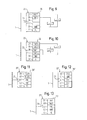
- FIG. 5 shows a coupling device designed according to the invention 22 shown in highly schematic form as a block diagram.
- the coupling device 22 comprised a connection unit 23 on the bus side, via which it is connected is connected to the bus system 1.
- the internal connection unit is on the bus side 23 with two internal control units 24, 25 designed as CPUs connected.
- a device-side connection unit 26 which comprises six contact elements 27 to 32.
- the contact elements 27 to 30 are so-called variable contact elements trained, each internally with the control units 24, 25th are connected. Via the control units 24, 25 are each of the variable Contact elements 27 to 30 predetermined functional properties A, B, C, D assignable, these functional properties from a given Set of functional properties can be selected.
- the contact elements 31 and 32 are so-called fixed Contact elements formed, d. H. these two contact elements are with fixed predetermined functional properties, in the example according to FIG. 5, with the functional properties of mass (GND) and functional earth (FE) busy.
- connection lines 33 to 38 with corresponding inputs and outputs from Devices are connected, as follows with reference to Figures 6 to 15 is described in more detail.
- connection of the safety switch 16 from Figure 2 is on the coupling device 22 designed according to the invention is shown.
- the signals IN1, IN2, TOUT1 and TOUT2 required.
- the fixed contact elements 31, 32 are in not needed in this case.
- the safety switch 16 is thus read out or tested at Use of a coupling device designed according to the invention identical to the use of a coupling device according to the prior art Technology according to Figure 2, so that on the part of the user no change here is required.
- the contact element 27 is supplied with the supply voltage (24 Volts), the contact element 29 with IN1 and the contact element 30 with IN2 busy.
- the safety light barrier 17 is then connected identically according to the connection according to Figure 3, with the variable assignment of the individual functional properties to the contact elements 27 to 30 it is ensured that with the circuit shown in FIG desired functionality according to Figure 3 is achieved.
- the contact element 28 is not required in this connection, so that here this contact element 28 either with the standard value TOUT2 or with any other functional property can be wired. It is also possible that the contact element 28 is not connected in this case, as is shown in FIG. 7 by a cross is shown.
- the two-channel ones are tested Outputs OSSD1 and OSSD2 of the safety light barrier 17 with connected to the two signal inputs IN1, IN2.
- the power supply the safety light barrier takes place via the contact element 27 for example 24 volts.
- the safety light barrier covers the wiring 17 shorts between the two output lines OSSD1 and OSSD2 and short circuits to 24 volts or ground (GND) on.
- Figure 8 shows the parameterization of the designed according to the invention Coupling device when connecting the standard sensor 18 from FIG 4.
- the contact element 27 is powered (24 volts), the contact element 28 with TOUT2 and the contact element 29 with IN1.
- the contact element 30 is not required in this case and can be assigned, for example, by the standard value IN2 or also be not connected, as indicated by a cross in FIG. 8.
- circuitry is identical to the circuitry shown in FIG. 4, see above that with the corresponding parameterization of the contact elements 27 to 29 the same functionality as with the coupling device the prior art according to Figure 4 is achieved.
- the standard sensor 18 receives its voltage supply via the contact element 27 (24 volts). The sensor 18 is tested via the test output TOUT2 (contact element 28), while the switching output 21 of the Sensor is read via the contact element 29 (IN1).
- the two can be used for two-channel safety outputs Contact elements 27 and 28 as self-testing safe switching outputs TOUT1 and TOUT2 are executed.
- This allows the security category Reach 4 according to EN 954 or SIL 3 according to IEC 62508. If one lower security category is sufficient, the expression also take place in a single channel.
- the integrated control units in turn provide the necessary control 24 and 25 carried out, which by corresponding over the Bus system 1 transmitted control signals can be controlled.
- the two contact elements 27, 28 as high-active switching outputs TOUT1H and TOUT2H can be designed, while the two contact elements 29 and 30 parameterized as low-active switching outputs TOUT1L and TOUT2L as shown in Figure 10. It is still on it point out that in the entire description switching outputs that are not explicitly described otherwise, basically as high-active Switching outputs are to be understood. Basically, the invention however also with coupling devices with low-active switching outputs be used.
- the contact elements 31 and 32 not required, as can be seen from FIG. 10. Basically you can these in turn, as shown in Figure 5, formed as fixed contact elements his. However, it is also possible for all contact elements 27 to 32 are designed as variable contact elements, and thus an increased Get flexibility.
- FE functional earth
- FIGS. 11 to 15 differ compared to the embodiments according to FIGS. 6 to 10 in that only five contact elements 39 to 43 are provided. Accordingly the coupling devices with 22 'and the device-side connection units designated 26 '.
- Figures 11 to 15 show further possible parameterizations of the contact elements 39 to 43.
- the contact elements 39 and 40 as test outputs TOUT1, TOUT2, the contact elements 41 and 42 as Signal inputs IN1, IN2 and the contact element 43 as functional earth FE parameterized.
- the contact element 43 for example, not as a variable contact element, but as fixed contact element is formed, so the internal circuitry for the coupling device 22 'according to the invention. With the assignment shown in FIG A safety switch 16 according to FIG. 2 can be connected.
- the functional earth FE can be connected directly to the contact element 43, so that in this embodiment the use of the housing contact is not required. This can further reduce costs become.
- the contact element 39 with voltage supply the contact element 40 with signal input 1, the contact element 41 with signal input 2 and the contact element 42 is grounded (GND).
- the contact element 43 can in turn be assigned with functional earth either fixed or variable his.
- the contact elements 40 and 41 are included as signal inputs internal pull-down resistor or with internal pull-up resistor executed as it is characterized by the designations IN1-pd and IN2-pu is.
- the Contact elements 39 and 42 as fixed contact elements with that shown Train occupancy and only the contact elements 40 and 41 as variable To provide contact elements.
- the safety light barrier is connected 17 possible on the identical contact elements, see above that in turn only four contact elements for the actual connection the safety light barrier are required and thus functional earth can be placed on the fifth contact element.
- the connection via the connector housing is again not required in this case.
Landscapes
- Physics & Mathematics (AREA)
- General Physics & Mathematics (AREA)
- Engineering & Computer Science (AREA)
- Automation & Control Theory (AREA)
- Details Of Connecting Devices For Male And Female Coupling (AREA)
- Small-Scale Networks (AREA)
- Cable Transmission Systems, Equalization Of Radio And Reduction Of Echo (AREA)
Abstract
Description
- statische Versorgungsspannung (üblicherweise 24 Volt)
- Potential Masse (GND)
- Signaleingang 1 (IN1)
- Signaleingang 2 (IN2)
- Testausgang 1 (TOUT1)
- Testausgang 2 (TOUT2)
- Funktionserde (FE)
- IP 67 M12 8-polig
- IP 67 M18 8-polig
- IP 67 M23 12-polig
- Figur 1
- ein Blockdiagramm eines Bussystems, an das über eine erfindungsgemäße Kopplungsvorrichtung drei unterschiedliche Geräte angeschlossen sind,
- Figuren 2 - 4
- schematische Darstellungen einer Kopplungsvorrichtung nach dem Stand der Technik mit verschiedenen Beschaltungen,
- Figur 5
- eine schematische Darstellung des Aufbaus einer erfindungsgemäß ausgebildeten Kopplungsvorrichtung und
- Figuren 6 - 15
- verschiedene Ausführungsformen einer erfindungsgemäß ausgebildeten Kopplungsvorrichtung mit unterschiedlichen Beschaltungen.
- 1
- Bussystem
- 1'
- Busleitung
- 2
- Kopplungsvorrichtung
- 3
- Sicherheitsschalter
- 4
- Sicherheitslichtschranke
- 5
- Standardsensor
- 6
- Kopplungsvorrichtung
- 7
- busseitige Anschlusseinheit
- 8
- geräteseitige Anschlusseinheit
- 9
- Kontaktelement
- 10
- Kontaktelement
- 11
- Kontaktelement
- 12
- Kontaktelement
- 13
- Kontaktelement
- 14
- Kontaktelement
- 15
- Kontaktelement
- 16
- Sicherheitsschalter
- 17
- Sicherheitslichtschranke
- 18
- testbarer Standardsensor
- 19
- Signalausgang
- 20
- Signalausgang
- 21
- Ausgang
- 22
- Kopplungsvorrichtung
- 22'
- Kopplungsvorrichtung
- 23
- busseitige Anschlusseinheit
- 24
- interne Steuereinheit
- 25
- interne Steuereinheit
- 26
- geräteseitige Anschlusseinheit
- 26'
- geräteseitige Anschlusseinheit
- 27
- Kontaktelement
- 28
- Kontaktelement
- 29
- Kontaktelement
- 30
- Kontaktelement
- 31
- Kontaktelement
- 32
- Kontaktelement
- 33
- Verbindungsleitung
- 34
- Verbindungsleitung
- 35
- Verbindungsleitung
- 36
- Verbindungsleitung
- 37
- Verbindungsleitung
- 38
- Verbindungsleitung
- 39
- Kontaktelement
- 40
- Kontaktelement
- 41
- Kontaktelement
- 42
- Kontaktelement
- 43
- Kontaktelement
Claims (27)
- Kopplungsvorrichtung zum Anschließen von Geräten (16, 17, 18) wie beispielsweise Sensoren, Aktoren, berührungslos wirkenden Schutzeinrichtungen (BWS), Lichtschranken oder Steuerungen an ein Bussystem (1), mit zumindest einer busseitigen Anschlusseinheit (23) zum Anschließen der Kopplungsvorrichtung (22, 22') an das Bussystem (1) und mit zumindest einer geräteseitigen Anschlusseinheit (26, 26') zum Anschließen eines Gerätes (16, 17, 18) an die Kopplungsvorrichtung (22, 22'), wobei die geräteseitige Anschlusseinheit (23) n (n> 1) Kontaktelemente (37 - 32, 39 - 43) umfasst, von denen jedes eine aus einer Menge von m (m>1) vordefinierten Funktionseigenschaften (A, B, C, D) besitzt,
dadurch gekennzeichnet, dass zumindest ein Teil der Kontaktelemente als variable Kontaktelemente (27 - 30, 39 - 42) ausgebildet ist, die jeweils variabel mit je einer der vordefinierten Funktionseigenschaften (A, B, C, D) belegbar sind. - Kopplungsvorrichtung nach Anspruch 1,
dadurch gekennzeichnet, dass ein Teil der Kontaktelemente als feste Kontaktelemente (31, 32, 43) ausgebildet ist, die jeweils fest mit je einer vorgegebenen Funktionseigenschaft (GND, FE) belegt sind, während die restlichen Kontaktelemente (27 - 30, 39 - 42) jeweils variabel mit je einer Funktionseigenschaft (A, B, C, D) belegbar sind. - Kopplungsvorrichtung nach einem der vorhergehenden Ansprüche,
dadurch gekennzeichnet, dass zumindest ein Teil der variablen Kontaktelemente (27 - 30, 39 - 42) jeweils mit der gleichen Funktionseigenschaft (A, B, C, D) belegbar ist. - Kopplungsvorrichtung nach einem der vorhergehenden Ansprüche,
dadurch gekennzeichnet, dass zumindest einige der variablen Kontaktelemente (27 - 30, 39 - 42) mit voneinander verschiedenen Funktionseigenschaften (A, B, C, D) belegbar sind. - Kopplungsvorrichtung nach einem der vorhergehenden Ansprüche,
dadurch gekennzeichnet, dass die Anzahl der geräteseitigen Kontaktelemente(37 - 32, 39 - 43) m größer, gleich oder kleiner als die Anzahl der vordefinierten Funktionseigenschaften (A, B, C, D) n ist. - Kopplungsvorrichtung nach einem der vorhergehenden Ansprüche,
dadurch gekennzeichnet, dass die vordefinierten Funktionseigenschaften (A, B, C, D) aus folgenden Eigenschaften wählbar sind: Statische Versorgungsspannung (positiv oder negativ), Masse (GND), Signaleingang, Testausgang, Funktionserde, Schaltausgang, Signaleingang mit Pull-up-Widerstand, Signaleingang mit Pull-down-Widerstand, null Volt und keine Funktion. - Kopplungsvorrichtung nach einem der vorhergehenden Ansprüche,
dadurch gekennzeichnet, dass eines der Kontaktelemente (32) als Gehäuseteil der geräteseitigen Anschlusseinheit (26, 26') ausgebildet ist. - Kopplungsvorrichtung nach einem der vorhergehenden Ansprüche,
dadurch gekennzeichnet, dass die Kopplungsvorrichtung (22, 22') zum Anschluss von sicheren Geräten (Sicherheitsgeräten) (16, 17) ausgebildet ist. - Kopplungsvorrichtung nach einem der vorhergehenden Ansprüche,
dadurch gekennzeichnet, dass die Kopplungsvorrichtung (22, 22') zum Anschluss an ein sicheres Bussystem (Sicherheitsbussystem) (1) ausgebildet ist. - Kopplungsvorrichtung nach einem der vorhergehenden Ansprüche,
dadurch gekennzeichnet, dass die geräteseitige Anschlusseinheit (26') fünf Kontaktelemente (39 - 43) umfasst. - Kopplungsvorrichtung nach einem der Ansprüche 1 bis 9,
dadurch gekennzeichnet, dass die geräteseitige Anschlusseinheit (26) sechs Kontaktelemente (27 - 32) umfasst, wobei eines der Kontaktelemente (32) als Gehäusekontakt, d.h. als Gehäuseteil der geräteseitigen Anschlusseinheit (26) ausgebildet ist. - Kopplungsvorrichtung nach Anspruch 11,
dadurch gekennzeichnet, dass der Gehäusekontakt (32) fest mit Funktionserde FE belegt ist. - Kopplungsvorrichtung nach einem der vorhergehenden Ansprüche,
dadurch gekennzeichnet, dass ein festes Kontaktelement (29) als erster Signaleingang (IN1), ein festes Kontaktelement (30) als zweiter Signaleingang (IN2) und ein festes Kontaktelement (31) als Masse (GND) fest eingestellt ist, während zwei variable Kontaktelemente jeweils variabel als erster oder zweiter Testausgang (TOUT1, TOUT2) einstellbar oder mit statischer Versorgungsspannung oder mit 0 V belegbar sind. - Kopplungsvorrichtung nach einem der Ansprüche 1 bis 12,
dadurch gekennzeichnet, dass ein festes Kontaktelement (31) als Masse (GND) fest eingestellt ist, während jeweils zwei variable Kontaktelemente (27, 28) als erster und zweiter Testausgang (TOUT1H, TOUT2H) und zwei weitere variable Kontaktelemente (29, 30) als jeweils low-aktiver erster und zweiter Schaltausgang (TOUT1L, TOUT2L) einstellbar sind. - Kopplungsvorrichtung nach einem der Ansprüche 1 bis 12,
dadurch gekennzeichnet, dass ein festes Kontaktelement (27) als erster Schaltausgang (TOUT1H), ein festes Kontaktelement (28) als zweiter Schaltausgang (TOUT2H) und ein festes Kontaktelement (31) als Masse (GND) fest eingestellt ist, während zwei variable Kontaktelemente (29, 30) jeweils variabel als erster und zweiter Signaleingang (IN1, IN2) oder als jeweils low-aktiver erster und zweiter Schaltausgang (TOUT1L, TOUT2L) einstellbar sind. - Kopplungsvorrichtung nach einem der Ansprüche 1 bis 12,
dadurch gekennzeichnet, dass ein festes Kontaktelement (31) fest mit Masse (GND) belegt ist, während vier variable Kontaktelemente (27 - 30) jeweils variabel als beliebige Kombination von Signaleingängen (IN1, IN2) und Schaltausgängen (TOUT1, TOUT2) einstellbar sind. - Kopplungsvorrichtung nach einem der Ansprüche 1 bis 12,
dadurch gekennzeichnet, dass ein festes Kontaktelement (43) fest mit Funktionserde (FE) belegt ist, während vier variable Kontaktelemente (39 - 42) jeweils variabel als beliebige Kombination von Signaleingängen (IN1, IN2), Schaltausgängen (TOUT1, TOUT2), Masse (GND) und statischer Versorgungsspannung einstellbar sind. - Kopplungsvorrichtung nach einem der Ansprüche 1 bis 12,
dadurch gekennzeichnet, dass ein festes Kontaktelement (43) fest mit Funktionserde (FE), ein festes Kontaktelement (42) mit Masse (GND) und ein festes Kontaktelement (39) mit statischer Versorgungsspannung fest belegt ist, während zwei variable Kontaktelemente (40, 41) jeweils variabel als Signaleingänge mit Pull-up-Widerstand oder mit Pull-down-Widerstand (IN1-pu, IN2-pu, IN1-pd, IN2-pd) einstellbar sind. - Kopplungsvorrichtung nach einem der Ansprüche 1 bis 12,
dadurch gekennzeichnet, dass ein festes Kontaktelement (43) fest mit Funktionserde (FE), ein festes Kontaktelement (42) mit Masse (GND), ein festes Kontaktelement (39) mit statischer Versorgungsspannung und ein festes Kontaktelement (40) als Signaleingang mit Pull-down-Widerstand (IN1-pd) fest belegt ist, während ein variables Kontaktelement (41) variabel als Signaleingang mit Pull-up-Widerstand (IN2-pu) oder als Signaleingang mit Pull-down-Widerstand (IN2-pd) einstellbar ist. - Kopplungsvorrichtung nach einem der vorhergehenden Ansprüche
dadurch gekennzeichnet, dass innerhalb der Kopplungsvorrichtung (22, 22') zumindest eine interne Steuereinheit (24, 25) vorgesehen ist, über die Zuordnung der Funktionseigenschaften (A, B, C, D) an die variablen Kontaktelemente (27 - 30) steuerbar ist. - Kopplungsvorrichtung nach Anspruch 20,
dadurch gekennzeichnet, dass die interne Steuereinheit (24, 25) ein Softwaresteuermodul umfasst. - Kopplungsvorrichtung nach Anspruch 20 oder 21,
dadurch gekennzeichnet, dass zur Erzeugung einer sicheren Kopplungsvorrichtung (22, 22') zwei redundante interne Steuereinheiten (24, 25) vorgesehen sind. - Kopplungsvorrichtung nach einem der vorhergehenden Ansprüche
dadurch gekennzeichnet, dass zur Belegung der variablen Kontaktelemente (27 - 30) eine externe Steuereinheit, insbesondere ein Personalcomputer anschließbar ist, über die die interne(n) Steuereinheit(en) (24, 25) ansteuerbar ist/sind. - Kopplungsvorrichtung nach Anspruch 23,
dadurch gekennzeichnet, dass ein separater Steueranschluss zum Anschließen der externen Steuereinheit an die Kopplungsvorrichtung vorgesehen ist. - Kopplungsvorrichtung nach Anspruch 23 oder 24,
dadurch gekennzeichnet, dass Steuerdaten von der externen Steuereinheit über das Bussystem (1) und die busseitige Anschlusseinheit (23) an die Kopplungsvorrichtung (22, 22') übertragbar sind. - Kopplungsvorrichtung nach einem der vorhergehenden Ansprüche,
dadurch gekennzeichnet, dass die geräteseitige Anschlusseinheit als fünfpoliger Steckverbinder oder als fünfpoliger Steckverbinder mit Gehäusekontakt als sechstem Pol ausgebildet ist. - Kopplungsvorrichtung nach Anspruch 26,
dadurch gekennzeichnet, dass die geräteseitige Anschlusseinheit als M12 5-poliger Rundsteckverbinder oder als M12 5-poliger Rundsteckverbinder mit Gehäuseabschirmung ausgebildet ist.
Applications Claiming Priority (2)
| Application Number | Priority Date | Filing Date | Title |
|---|---|---|---|
| DE10211938.4A DE10211938B4 (de) | 2002-03-18 | 2002-03-18 | Kopplungsvorrichtung zum Anschließen von Geräten an ein Bussystem |
| DE10211938 | 2002-03-18 |
Publications (2)
| Publication Number | Publication Date |
|---|---|
| EP1347388A1 true EP1347388A1 (de) | 2003-09-24 |
| EP1347388B1 EP1347388B1 (de) | 2008-05-07 |
Family
ID=27771404
Family Applications (1)
| Application Number | Title | Priority Date | Filing Date |
|---|---|---|---|
| EP03003435A Revoked EP1347388B1 (de) | 2002-03-18 | 2003-02-14 | Kopplungsvorrichtung zum Anschliessen von Geräten an ein Bussystem |
Country Status (5)
| Country | Link |
|---|---|
| US (1) | US20030212849A1 (de) |
| EP (1) | EP1347388B1 (de) |
| JP (1) | JP2003303037A (de) |
| AT (1) | ATE394739T1 (de) |
| DE (2) | DE10211938B4 (de) |
Cited By (4)
| Publication number | Priority date | Publication date | Assignee | Title |
|---|---|---|---|---|
| WO2010043458A1 (de) * | 2008-10-17 | 2010-04-22 | Siemens Aktiengesellschaft | Sicherheitseinrichtung zur überwachung eines sensors |
| WO2011058276A1 (fr) * | 2009-11-13 | 2011-05-19 | Max Power | Système de gestion du fonctionnement de différents organes fonctionnels embarqués à bord d'un bateau |
| US9477212B2 (en) | 2010-12-06 | 2016-10-25 | Pilz Gmbh & Co. Kg | Safety switching device for the failsafe shutdown of an electrical load |
| EP2725172B1 (de) | 2012-10-25 | 2018-06-27 | ASSA ABLOY Sicherheitstechnik GmbH | Verfahren zum Betreiben einer Rettungswegvorrichtung sowie Rettungsweganordnung |
Families Citing this family (5)
| Publication number | Priority date | Publication date | Assignee | Title |
|---|---|---|---|---|
| DE102004018642A1 (de) | 2004-04-16 | 2005-12-01 | Sick Ag | Prozesssteuerung |
| JP3918950B2 (ja) | 2005-04-19 | 2007-05-23 | オムロン株式会社 | セーフティデバイス |
| EP1887444B1 (de) | 2006-08-10 | 2008-12-03 | Sick Ag | Prozesssteuerung |
| DE102015113365B4 (de) * | 2015-08-13 | 2021-03-25 | Sick Ag | Lichtgitter |
| DE102021107852A1 (de) | 2021-03-29 | 2022-09-29 | Vega Grieshaber Kg | Sensor mit Mitteln für eine frei konfigurierbare Kontaktbelegung, Verfahren zur frei konfigurierbaren Kontaktbelegung eines Sensors und Adapter |
Citations (4)
| Publication number | Priority date | Publication date | Assignee | Title |
|---|---|---|---|---|
| US4972470A (en) * | 1987-08-06 | 1990-11-20 | Steven Farago | Programmable connector |
| DE4417423A1 (de) * | 1994-05-18 | 1995-10-05 | Siemens Ag | Schnittstellenanpassung |
| DE19756167A1 (de) * | 1997-12-17 | 1999-07-08 | Ifm Electronic Gmbh | Koppelmodul zum Anschluß eines Anwendermoduls |
| DE29919901U1 (de) * | 1999-11-13 | 2001-04-05 | Weidmüller Interface GmbH & Co, 32760 Detmold | Verteiler zum Verbinden von Aktoren und/oder Sensoren |
Family Cites Families (7)
| Publication number | Priority date | Publication date | Assignee | Title |
|---|---|---|---|---|
| US3950058A (en) * | 1973-11-05 | 1976-04-13 | Lockheed Aircraft Corporation | Programmable wiring system and junction box for use therein |
| JPS6048681U (ja) * | 1983-09-09 | 1985-04-05 | 株式会社 テクノパ−ク峰 | スイツチ付ケ−ブル |
| US4718853A (en) * | 1986-10-01 | 1988-01-12 | Gte Products Corporation | Four pole, vehicle-trailer electrical connector |
| US5442170B1 (en) * | 1994-04-15 | 1996-11-05 | Snap On Tech Inc | Programmable cable adaptor for connecting different automobile computers to diagnostic equipment |
| DE19703159A1 (de) * | 1997-01-29 | 1998-07-30 | Abb Patent Gmbh | Ein/Ausgabeeinrichtung für Installationsbussysteme |
| DE19832398A1 (de) * | 1998-07-18 | 2000-01-20 | Merten Gmbh & Co Kg Geb | Anschlußeinrichtung für die Gebäudesystemtechnik |
| TW459425B (en) * | 2000-06-23 | 2001-10-11 | Primax Electronics Ltd | Power socket apparatus |
-
2002
- 2002-03-18 DE DE10211938.4A patent/DE10211938B4/de not_active Expired - Lifetime
-
2003
- 2003-02-14 DE DE50309760T patent/DE50309760D1/de not_active Expired - Lifetime
- 2003-02-14 EP EP03003435A patent/EP1347388B1/de not_active Revoked
- 2003-02-14 AT AT03003435T patent/ATE394739T1/de not_active IP Right Cessation
- 2003-03-12 US US10/388,380 patent/US20030212849A1/en not_active Abandoned
- 2003-03-17 JP JP2003072443A patent/JP2003303037A/ja active Pending
Patent Citations (4)
| Publication number | Priority date | Publication date | Assignee | Title |
|---|---|---|---|---|
| US4972470A (en) * | 1987-08-06 | 1990-11-20 | Steven Farago | Programmable connector |
| DE4417423A1 (de) * | 1994-05-18 | 1995-10-05 | Siemens Ag | Schnittstellenanpassung |
| DE19756167A1 (de) * | 1997-12-17 | 1999-07-08 | Ifm Electronic Gmbh | Koppelmodul zum Anschluß eines Anwendermoduls |
| DE29919901U1 (de) * | 1999-11-13 | 2001-04-05 | Weidmüller Interface GmbH & Co, 32760 Detmold | Verteiler zum Verbinden von Aktoren und/oder Sensoren |
Cited By (4)
| Publication number | Priority date | Publication date | Assignee | Title |
|---|---|---|---|---|
| WO2010043458A1 (de) * | 2008-10-17 | 2010-04-22 | Siemens Aktiengesellschaft | Sicherheitseinrichtung zur überwachung eines sensors |
| WO2011058276A1 (fr) * | 2009-11-13 | 2011-05-19 | Max Power | Système de gestion du fonctionnement de différents organes fonctionnels embarqués à bord d'un bateau |
| US9477212B2 (en) | 2010-12-06 | 2016-10-25 | Pilz Gmbh & Co. Kg | Safety switching device for the failsafe shutdown of an electrical load |
| EP2725172B1 (de) | 2012-10-25 | 2018-06-27 | ASSA ABLOY Sicherheitstechnik GmbH | Verfahren zum Betreiben einer Rettungswegvorrichtung sowie Rettungsweganordnung |
Also Published As
| Publication number | Publication date |
|---|---|
| DE10211938B4 (de) | 2016-11-10 |
| DE10211938A1 (de) | 2003-10-02 |
| EP1347388B1 (de) | 2008-05-07 |
| US20030212849A1 (en) | 2003-11-13 |
| ATE394739T1 (de) | 2008-05-15 |
| DE50309760D1 (de) | 2008-06-19 |
| JP2003303037A (ja) | 2003-10-24 |
Similar Documents
| Publication | Publication Date | Title |
|---|---|---|
| EP3069202B1 (de) | Sicherheitssteuerung mit konfigurierbaren eingängen | |
| EP0712267B1 (de) | Modulare Steuerungsanlage mit integriertem Feldbusanschluss | |
| EP2649496B1 (de) | Sicherheitsschaltgerät zum fehlersicheren abschalten eines elektrischen verbrauchers | |
| DE69505274T2 (de) | Fensterkomparator mit echter hysterese | |
| EP0546455B1 (de) | Elektronische Steuereinrichtung zum Schalten mehrerer elektrischer Lasten | |
| DE3116079A1 (de) | Pruefsystem | |
| DE4441070C2 (de) | Sicherheitsschalteranordnung | |
| DE69933839T2 (de) | Verfahren und Vorrichtung zur Detektion von Leitungsshunt und Erdschlussfehler | |
| EP2007077A1 (de) | Verfahren zum Ermitteln der Position von Slavegeräten in einer Reihenschaltung und Slavegerät für Reihenschaltung | |
| EP1347388B1 (de) | Kopplungsvorrichtung zum Anschliessen von Geräten an ein Bussystem | |
| WO2010097347A1 (de) | Sicherheitssystem mit kontrolleinrichtung | |
| EP0775332B1 (de) | Sicherheitsschalteranordnung | |
| EP1603282A1 (de) | Verfahren zur Adressierung der Teilnehmer eines Bussystems | |
| DE212012000249U1 (de) | Vorrichtung zum eigensicheren Versorgen, Ansteuern und/oder Auswerten von Feldgeräten im explosionsgeschützten Bereich | |
| EP3557598A1 (de) | Sicherheitsschalter | |
| DE19508841C2 (de) | Sicherheitsschalteranordnung | |
| DE102020112985A1 (de) | IO-Link-Adapter | |
| EP1085691A2 (de) | System zur prozessorgesteuerten Übertragung von elektrischen Signalen und elektrischer Energie innerhalb eines militärischen Fahrzeugs | |
| EP1982242B1 (de) | Elektrofluidische ventilstation | |
| EP0763877B1 (de) | Kommunikationssystem | |
| EP3899558B1 (de) | Verfahren und prüfvorrichtung | |
| EP1068700B1 (de) | Signalisierungsendstufe zur erzeugung digitaler spannungssignale auf einem bussystem | |
| DE102008044115A1 (de) | Schaltelement, Busschaltsystem, Steuereinheit und Verfahren zum Erkennen von Schalterstellungen einer Mehrzahl von Schaltelementen | |
| DE3614208C2 (de) | Anordnung zum Anschluß einer Leistungsausgabeschaltung an eine Buskoppeleinrichtung | |
| DE102012004944B4 (de) | Verfahren zum Überprüfen der Funktion von elektrischen Anschlüssen eines analogen oder digitalen Schaltkreises |
Legal Events
| Date | Code | Title | Description |
|---|---|---|---|
| PUAI | Public reference made under article 153(3) epc to a published international application that has entered the european phase |
Free format text: ORIGINAL CODE: 0009012 |
|
| AK | Designated contracting states |
Kind code of ref document: A1 Designated state(s): AT BE BG CH CY CZ DE DK EE ES FI FR GB GR HU IE IT LI LU MC NL PT SE SI SK TR |
|
| AX | Request for extension of the european patent |
Extension state: AL LT LV MK RO |
|
| 17P | Request for examination filed |
Effective date: 20031107 |
|
| AKX | Designation fees paid |
Designated state(s): AT BE BG CH CY CZ DE DK EE ES FI FR GB GR HU IE IT LI LU MC NL PT SE SI SK TR |
|
| 17Q | First examination report despatched |
Effective date: 20050221 |
|
| RAP1 | Party data changed (applicant data changed or rights of an application transferred) |
Owner name: SICK AG |
|
| GRAP | Despatch of communication of intention to grant a patent |
Free format text: ORIGINAL CODE: EPIDOSNIGR1 |
|
| GRAS | Grant fee paid |
Free format text: ORIGINAL CODE: EPIDOSNIGR3 |
|
| GRAA | (expected) grant |
Free format text: ORIGINAL CODE: 0009210 |
|
| AK | Designated contracting states |
Kind code of ref document: B1 Designated state(s): AT BE BG CH CY CZ DE DK EE ES FI FR GB GR HU IE IT LI LU MC NL PT SE SI SK TR |
|
| REG | Reference to a national code |
Ref country code: GB Ref legal event code: FG4D Free format text: NOT ENGLISH |
|
| REG | Reference to a national code |
Ref country code: CH Ref legal event code: EP |
|
| REG | Reference to a national code |
Ref country code: IE Ref legal event code: FG4D Free format text: LANGUAGE OF EP DOCUMENT: GERMAN |
|
| REF | Corresponds to: |
Ref document number: 50309760 Country of ref document: DE Date of ref document: 20080619 Kind code of ref document: P |
|
| PG25 | Lapsed in a contracting state [announced via postgrant information from national office to epo] |
Ref country code: SI Free format text: LAPSE BECAUSE OF FAILURE TO SUBMIT A TRANSLATION OF THE DESCRIPTION OR TO PAY THE FEE WITHIN THE PRESCRIBED TIME-LIMIT Effective date: 20080507 |
|
| PG25 | Lapsed in a contracting state [announced via postgrant information from national office to epo] |
Ref country code: NL Free format text: LAPSE BECAUSE OF FAILURE TO SUBMIT A TRANSLATION OF THE DESCRIPTION OR TO PAY THE FEE WITHIN THE PRESCRIBED TIME-LIMIT Effective date: 20080507 Ref country code: ES Free format text: LAPSE BECAUSE OF FAILURE TO SUBMIT A TRANSLATION OF THE DESCRIPTION OR TO PAY THE FEE WITHIN THE PRESCRIBED TIME-LIMIT Effective date: 20080818 Ref country code: FI Free format text: LAPSE BECAUSE OF FAILURE TO SUBMIT A TRANSLATION OF THE DESCRIPTION OR TO PAY THE FEE WITHIN THE PRESCRIBED TIME-LIMIT Effective date: 20080507 |
|
| NLV1 | Nl: lapsed or annulled due to failure to fulfill the requirements of art. 29p and 29m of the patents act | ||
| REG | Reference to a national code |
Ref country code: IE Ref legal event code: FD4D |
|
| PG25 | Lapsed in a contracting state [announced via postgrant information from national office to epo] |
Ref country code: SE Free format text: LAPSE BECAUSE OF FAILURE TO SUBMIT A TRANSLATION OF THE DESCRIPTION OR TO PAY THE FEE WITHIN THE PRESCRIBED TIME-LIMIT Effective date: 20080807 Ref country code: PT Free format text: LAPSE BECAUSE OF FAILURE TO SUBMIT A TRANSLATION OF THE DESCRIPTION OR TO PAY THE FEE WITHIN THE PRESCRIBED TIME-LIMIT Effective date: 20081007 Ref country code: DK Free format text: LAPSE BECAUSE OF FAILURE TO SUBMIT A TRANSLATION OF THE DESCRIPTION OR TO PAY THE FEE WITHIN THE PRESCRIBED TIME-LIMIT Effective date: 20080507 Ref country code: CZ Free format text: LAPSE BECAUSE OF FAILURE TO SUBMIT A TRANSLATION OF THE DESCRIPTION OR TO PAY THE FEE WITHIN THE PRESCRIBED TIME-LIMIT Effective date: 20080507 Ref country code: IE Free format text: LAPSE BECAUSE OF FAILURE TO SUBMIT A TRANSLATION OF THE DESCRIPTION OR TO PAY THE FEE WITHIN THE PRESCRIBED TIME-LIMIT Effective date: 20080507 |
|
| PLBI | Opposition filed |
Free format text: ORIGINAL CODE: 0009260 |
|
| PG25 | Lapsed in a contracting state [announced via postgrant information from national office to epo] |
Ref country code: SK Free format text: LAPSE BECAUSE OF FAILURE TO SUBMIT A TRANSLATION OF THE DESCRIPTION OR TO PAY THE FEE WITHIN THE PRESCRIBED TIME-LIMIT Effective date: 20080507 |
|
| PLAX | Notice of opposition and request to file observation + time limit sent |
Free format text: ORIGINAL CODE: EPIDOSNOBS2 |
|
| 26 | Opposition filed |
Opponent name: PILZ GMBH & CO. KG Effective date: 20090209 |
|
| PG25 | Lapsed in a contracting state [announced via postgrant information from national office to epo] |
Ref country code: BG Free format text: LAPSE BECAUSE OF FAILURE TO SUBMIT A TRANSLATION OF THE DESCRIPTION OR TO PAY THE FEE WITHIN THE PRESCRIBED TIME-LIMIT Effective date: 20080807 Ref country code: EE Free format text: LAPSE BECAUSE OF FAILURE TO SUBMIT A TRANSLATION OF THE DESCRIPTION OR TO PAY THE FEE WITHIN THE PRESCRIBED TIME-LIMIT Effective date: 20080507 |
|
| PLBB | Reply of patent proprietor to notice(s) of opposition received |
Free format text: ORIGINAL CODE: EPIDOSNOBS3 |
|
| BERE | Be: lapsed |
Owner name: SICK A.G. Effective date: 20090228 |
|
| PG25 | Lapsed in a contracting state [announced via postgrant information from national office to epo] |
Ref country code: MC Free format text: LAPSE BECAUSE OF NON-PAYMENT OF DUE FEES Effective date: 20090228 |
|
| REG | Reference to a national code |
Ref country code: CH Ref legal event code: PL |
|
| PG25 | Lapsed in a contracting state [announced via postgrant information from national office to epo] |
Ref country code: CH Free format text: LAPSE BECAUSE OF NON-PAYMENT OF DUE FEES Effective date: 20090228 Ref country code: LI Free format text: LAPSE BECAUSE OF NON-PAYMENT OF DUE FEES Effective date: 20090228 |
|
| PG25 | Lapsed in a contracting state [announced via postgrant information from national office to epo] |
Ref country code: BE Free format text: LAPSE BECAUSE OF NON-PAYMENT OF DUE FEES Effective date: 20090228 |
|
| PLAY | Examination report in opposition despatched + time limit |
Free format text: ORIGINAL CODE: EPIDOSNORE2 |
|
| PG25 | Lapsed in a contracting state [announced via postgrant information from national office to epo] |
Ref country code: AT Free format text: LAPSE BECAUSE OF NON-PAYMENT OF DUE FEES Effective date: 20090214 |
|
| PG25 | Lapsed in a contracting state [announced via postgrant information from national office to epo] |
Ref country code: GR Free format text: LAPSE BECAUSE OF FAILURE TO SUBMIT A TRANSLATION OF THE DESCRIPTION OR TO PAY THE FEE WITHIN THE PRESCRIBED TIME-LIMIT Effective date: 20080808 |
|
| PLBC | Reply to examination report in opposition received |
Free format text: ORIGINAL CODE: EPIDOSNORE3 |
|
| PG25 | Lapsed in a contracting state [announced via postgrant information from national office to epo] |
Ref country code: LU Free format text: LAPSE BECAUSE OF NON-PAYMENT OF DUE FEES Effective date: 20090214 |
|
| PG25 | Lapsed in a contracting state [announced via postgrant information from national office to epo] |
Ref country code: HU Free format text: LAPSE BECAUSE OF FAILURE TO SUBMIT A TRANSLATION OF THE DESCRIPTION OR TO PAY THE FEE WITHIN THE PRESCRIBED TIME-LIMIT Effective date: 20081108 |
|
| PGFP | Annual fee paid to national office [announced via postgrant information from national office to epo] |
Ref country code: DE Payment date: 20110419 Year of fee payment: 9 |
|
| PG25 | Lapsed in a contracting state [announced via postgrant information from national office to epo] |
Ref country code: TR Free format text: LAPSE BECAUSE OF FAILURE TO SUBMIT A TRANSLATION OF THE DESCRIPTION OR TO PAY THE FEE WITHIN THE PRESCRIBED TIME-LIMIT Effective date: 20080507 |
|
| PG25 | Lapsed in a contracting state [announced via postgrant information from national office to epo] |
Ref country code: CY Free format text: LAPSE BECAUSE OF FAILURE TO SUBMIT A TRANSLATION OF THE DESCRIPTION OR TO PAY THE FEE WITHIN THE PRESCRIBED TIME-LIMIT Effective date: 20080507 |
|
| REG | Reference to a national code |
Ref country code: DE Ref legal event code: R103 Ref document number: 50309760 Country of ref document: DE Ref country code: DE Ref legal event code: R064 Ref document number: 50309760 Country of ref document: DE |
|
| RDAF | Communication despatched that patent is revoked |
Free format text: ORIGINAL CODE: EPIDOSNREV1 |
|
| RDAG | Patent revoked |
Free format text: ORIGINAL CODE: 0009271 |
|
| STAA | Information on the status of an ep patent application or granted ep patent |
Free format text: STATUS: PATENT REVOKED |
|
| PGFP | Annual fee paid to national office [announced via postgrant information from national office to epo] |
Ref country code: FR Payment date: 20120228 Year of fee payment: 10 |
|
| 27W | Patent revoked |
Effective date: 20111118 |
|
| GBPR | Gb: patent revoked under art. 102 of the ep convention designating the uk as contracting state |
Effective date: 20111118 |
|
| PGFP | Annual fee paid to national office [announced via postgrant information from national office to epo] |
Ref country code: IT Payment date: 20120224 Year of fee payment: 10 Ref country code: GB Payment date: 20120222 Year of fee payment: 10 |
|
| REG | Reference to a national code |
Ref country code: DE Ref legal event code: R107 Ref document number: 50309760 Country of ref document: DE Effective date: 20120712 |