EP1347211A1 - Cam block and method for manufacturing the same - Google Patents
Cam block and method for manufacturing the same Download PDFInfo
- Publication number
- EP1347211A1 EP1347211A1 EP01974754A EP01974754A EP1347211A1 EP 1347211 A1 EP1347211 A1 EP 1347211A1 EP 01974754 A EP01974754 A EP 01974754A EP 01974754 A EP01974754 A EP 01974754A EP 1347211 A1 EP1347211 A1 EP 1347211A1
- Authority
- EP
- European Patent Office
- Prior art keywords
- cam
- concave
- shaft
- extending portion
- hole
- Prior art date
- Legal status (The legal status is an assumption and is not a legal conclusion. Google has not performed a legal analysis and makes no representation as to the accuracy of the status listed.)
- Granted
Links
Images


Classifications
-
- F—MECHANICAL ENGINEERING; LIGHTING; HEATING; WEAPONS; BLASTING
- F01—MACHINES OR ENGINES IN GENERAL; ENGINE PLANTS IN GENERAL; STEAM ENGINES
- F01L—CYCLICALLY OPERATING VALVES FOR MACHINES OR ENGINES
- F01L1/00—Valve-gear or valve arrangements, e.g. lift-valve gear
- F01L1/02—Valve drive
- F01L1/04—Valve drive by means of cams, camshafts, cam discs, eccentrics or the like
- F01L1/08—Shape of cams
-
- F—MECHANICAL ENGINEERING; LIGHTING; HEATING; WEAPONS; BLASTING
- F01—MACHINES OR ENGINES IN GENERAL; ENGINE PLANTS IN GENERAL; STEAM ENGINES
- F01L—CYCLICALLY OPERATING VALVES FOR MACHINES OR ENGINES
- F01L1/00—Valve-gear or valve arrangements, e.g. lift-valve gear
- F01L1/02—Valve drive
- F01L1/022—Chain drive
-
- F—MECHANICAL ENGINEERING; LIGHTING; HEATING; WEAPONS; BLASTING
- F01—MACHINES OR ENGINES IN GENERAL; ENGINE PLANTS IN GENERAL; STEAM ENGINES
- F01L—CYCLICALLY OPERATING VALVES FOR MACHINES OR ENGINES
- F01L1/00—Valve-gear or valve arrangements, e.g. lift-valve gear
- F01L1/02—Valve drive
- F01L1/04—Valve drive by means of cams, camshafts, cam discs, eccentrics or the like
- F01L1/047—Camshafts
-
- F—MECHANICAL ENGINEERING; LIGHTING; HEATING; WEAPONS; BLASTING
- F16—ENGINEERING ELEMENTS AND UNITS; GENERAL MEASURES FOR PRODUCING AND MAINTAINING EFFECTIVE FUNCTIONING OF MACHINES OR INSTALLATIONS; THERMAL INSULATION IN GENERAL
- F16H—GEARING
- F16H53/00—Cams or cam-followers, e.g. rollers for gearing mechanisms
- F16H53/02—Single-track cams for single-revolution cycles; Camshafts with such cams
- F16H53/025—Single-track cams for single-revolution cycles; Camshafts with such cams characterised by their construction, e.g. assembling or manufacturing features
-
- F—MECHANICAL ENGINEERING; LIGHTING; HEATING; WEAPONS; BLASTING
- F01—MACHINES OR ENGINES IN GENERAL; ENGINE PLANTS IN GENERAL; STEAM ENGINES
- F01L—CYCLICALLY OPERATING VALVES FOR MACHINES OR ENGINES
- F01L2303/00—Manufacturing of components used in valve arrangements
Definitions
- the invention relates to a technique regarding a cam block made of metal and, more particularly, to a cam block which has an extending portion extending outwardly in one direction from a shaft through-hole for a cam shaft, is punched into an arc cam shape, and is suitable for use in on/off control or the like of, for example, an exhaust valve or an intake valve of an internal combustion engine and to a manufacturing method of such a cam block.
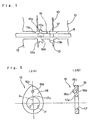
- a cam block which is used in, for example, an internal combustion engine of a motorcycle is generally constructed in a manner such that, for example, as shown in Fig. 5, a plate thickness is relatively thick, an outline having an extending portion 2 which extends outwardly in one direction from a shaft through-hole 1 has an arc cam shape, and the cam block is rotatably supported by inserting a cam shaft (not shown) into the shaft through-hole 1 by pressure.
- a material to be worked which has a thick plate shape and is made of metal is pressed by a punching operation and an outer peripheral plate pressing operation from one side and is also pressed by a die and an inner peripheral back pressing operation from the opposite side, thereby punching the material into an arc cam shape provided with the shaft through-hole 1 and working the cam block.
- an object of the invention to solve the conventional problem, suppress the occurrence of a cut break surface on a punched cut surface at the time of a punching work of a cam block, prevent a deterioration of a bore precision of a shaft through-hole, and eliminate a deviation of a position of contact with a follower, thereby improving operational precision.
- a cam block made of metal and having an arc-cam-shaped outline, comprising: a shaft through-hole into which a cam shaft is inserted by pressure; and an extending portion which extends outwardly in one direction from the shaft through-hole, characterized in that a convex portion is formed on one plate surface of the extending portion and a concave portion is formed on the other plate surface corresponding to the back side of the extending portion.
- the cam block of the invention is characterized in that in the case where the concave and convex portions are seen in the cam axial direction and a center line connecting a center of the shaft through-hole and an edge position of the extending portion existing at the farthest position from the center is used as a reference, the concave and convex portions are formed in positions within an angle range of about 10° to the right and left. Therefore, by forming the concave and convex portions at the positions where unevenness of the thickness mainly occurs upon punching work as mentioned above, unevenness of the thickness in the edge position direction of the extending portion can be effectively prevented. The number of cut break surfaces occurring on the punched cut surface can be further reduced.
- the cam block of the invention is characterized in that in the case where the concave and convex portions are seen in the cam axial direction, the concave and convex portions are arranged on a center line connecting a center of the shaft through-hole and an edge position of the extending portion existing in the farthest position from the center, that is, the concave and convex portions are formed in intermediate positions on a line segment connecting the edge position and a hole edge position of the shaft through-hole that is nearest to the edge position.
- the concave and convex portions of the cam block are formed in the positions where the best balance can be obtained on the extending portion as mentioned above, the unevenness of the thickness in the edge position direction of the extending portion can be effectively prevented, the number of cut break surfaces occurring in the punched cut surface can be further reduced, and the bore can be finished at high precision.
- the cam block of the invention is characterized in that the forming positions on the extending portion where the concave and convex portions are formed are made different every different arc-cam shape, thereby enabling them to be discriminated.
- the difference of the types of the cam blocks can be easily distinguished by the eyes at the time of the assembling work of the cam blocks, and the occurrence of the erroneous assembly can be easily and certainly prevented.
- the invention is characterized in that a thick plate-shaped material which is made of metal and should be worked is pressed by a punch and its outer peripheral plate pressing member, and the material is received by a die and its inner peripheral backward pressing member from an opposite side and pressed, thereby forming a shaft through-hole into which a cam shaft is inserted, the material is sheared into an arc-cam shape having an extending portion which extends outwardly in one direction from the shaft through-hole, thereby forming a cam block, wherein when the material to be worked is pressed by the punch and backward pressing member, a convex portion is formed on one plate surface of the extending portion and a concave portion is formed on the other plate surface corresponding to the back side of the extending portion.
- a manufacturing method of a cam block according to the invention is characterized in that in the case where the concave and convex portions are seen in the cam axial direction and a center line connecting a center of the shaft through-hole and an edge position of the extending portion existing at the farthest position from the center is used as a reference, the concave and convex portions are formed in positions within an angle range of about 10° to the right and left. Therefore, by forming the concave and convex portions at the positions where unevenness of the thickness mainly occurs upon punching work as mentioned above, unevenness of the thickness in the edge position direction of the extending portion can be effectively prevented. The number of cut break surfaces occurring on the punched cut surface can be further reduced.
- a manufacturing method of a cam block according to the invention is characterized in that in the case where the concave and convex portions are seen in the cam axial direction, the concave and convex portions are arranged on a center line connecting a center of the shaft through-hole and an edge position of the extending portion existing at the farthest position from the center, that is, the concave and convex portions are formed in intermediate positions on a line segment connecting the edge position and a hole edge position of the shaft through-hole that is nearest to the edge position.
- the concave and convex portions of the cam block are formed in the positions where the best balance can be obtained on the extending portion as mentioned above, the unevenness of the thickness in the edge position direction of the extending portion can be effectively prevented, the number of cut break surfaces occurring in the punched cut surface can be further reduced, and the bore can be finished at high precision.
- a manufacturing method of a cam block according to the invention is characterized in that the forming positions on the extending portion where the concave and convex portions are formed are made different every different arc-cam shape, thereby enabling them to be discriminated. Therefore, the difference of the types of the cam blocks can be easily distinguished by the eyes at the time of the assembling work of the cam blocks, and the occurrence of the erroneous assembly can be easily and certainly prevented.
- Fig. 1 shows an example of a die which is used in the case of punching a cam block by using a manufacturing method according to the invention.
- Figs. 2A and 2B show the cam block obtained by being punched by the manufacturing method of the invention.
- a cam block for example, a cam block which is used for an opening/closing control of an exhaust valve or an intake valve of an internal combustion engine for a motorcycle will be explained.
- reference numeral 15 denotes a cam block made of metal and having an arc-cam-shaped outline.
- the cam block 15 has: a shaft through-hole 17 into which a cam shaft 20 (which will be explained hereinlater)made of metal is inserted by pressure; and an extending portion 16 which extends outwardly in one direction from the shaft through-hole 17.
- a convex portion 16a is formed on one plate surface of the extending portion 16 of the cam block 15 and a concave portion 16b is formed on the other plate surface corresponding to the back side of the extending portion 16.
- the die for punching the cam block 15 is fundamentally used in the case of finely shearing it by, for example, a fine blanking method.
- An upper die of the die has a punch 10 and a plate pressing member 11 arranged at an outer peripheral position thereof, and a lower die has a die 12, a backward pressing member 13 arranged at an inner peripheral position of a hole of the die 12, and the like.
- the plate pressing member 11 has an annular projection 11a on a pressurizing surface on the lower side.
- the punch 10 has a shape such that a cylindrical concave 10a adapted to form the convex portion 16a is formed on the lower pressurizing surface corresponding to an outline curve of the cam block 15.
- the backward pressing member 13 which faces the punch 10 is formed in a shape such that a cylindrical projection 13a adapted to form the concave portion 16b is provided at the position corresponding to the concave 10a of the punch 10 and a cylindrical projection 13b adapted to punch the shaft through-hole 17 is provided.
- the punch 10 is moved downward together with the plate pressing member 11 by a pressing apparatus (not shown) and the annular projection 11a is thrust into the surface of a thick-plate-like material (blank) B which is made of metal and should be worked at a position around a shearing outline, thereby pressing the material B.
- the material B is received by the die 12 and backward pressing member 13 and pressed, thereby shearing the outline into an arc-cam shape also as shown in Fig. 2 and working the cam block 15.
- the cylindrical convex portion 16a is formed on one plate surface of the extending portion 16 in accordance with the concave 10a of the punch 10, the shaft through-hole 17 is formed by punching the other plate surface by the projection 13b of the backward pressing member 13, and at the same time, the concave portion 16b is formed on the back side of the convex portion 16a by half-punching the material B by the projection 13a.
- the concave and convex portions 16b and 16a are formed in the plate thickness direction of the extending portion 16, unevenness of the thickness in the direction of an edge position 16c of the extending portion 16 is prevented.
- the cam block 15 is positioned and supported by using a positioning tool (not shown) and the cam shaft 20 is inserted and penetrated by pressure into the shaft through-hole 17 as shown in Fig. 3.
- a positioning tool not shown
- two cam blocks 15 are positioned by deviating phases by a predetermined angle and assembled to the cam shaft 20 and a gear 21 is similarly assembled thereto, thereby forming a cam assembly C.
- a timing gear (not shown) attached onto a crank shaft which is rotated synchronously with an engine cycle is come into engagement with the gear 21, thereby rotating the cam shaft 20.
- the cam blocks 15 are rotated in accordance with the rotation of the cam shaft 20, thereby performing an opening/closing control of an exhaust valve or an intake valve.
- the concave and convex portions 16b and 16a of the cam block 15 are formed on the extending portion 16 as mentioned above.
- the center line S is used as a reference and they are formed in positions within an angle range of, for example, about 10° to the right and left.
- each of the concave and convex portions 16b and 16a has the cylindrical shape, it can also have another proper shape like a prism or the like.
- the invention has been described with respect to the example of the cam blocks which are used in the internal combustion engine for a motorcycle and the manufacturing method of such cam blocks, the invention can be also widely applied to a case of a cam having an arc-cam shape which is used in any apparatus other than the internal combustion engine and a manufacturing method of such a cam block.
- the invention is useful as a cam block made of metal which is used in various internal combustion engines for a motorcycle and the like and also suitable for manufacturing such a kind of cam block. Further, it is also useful as a cam block having an arc-cam shape which is used in any apparatus other than the internal combustion engine and suitable for manufacturing such a kind of cam block.
Landscapes
- Engineering & Computer Science (AREA)
- General Engineering & Computer Science (AREA)
- Mechanical Engineering (AREA)
- Valve-Gear Or Valve Arrangements (AREA)
- Punching Or Piercing (AREA)
- Gears, Cams (AREA)
- Shaping Metal By Deep-Drawing, Or The Like (AREA)
Abstract
Description
Claims (8)
- A cam block made of metal and having an arc-cam-shaped outline, comprising: a shaft through-hole into which a cam shaft is inserted by pressure; and an extending portion which extends outwardly in one direction from said shaft through-hole,
wherein a convex portion is formed on one plate surface of said extending portion and a concave portion is formed on the other plate surface corresponding to the back side of said extending portion. - A cam block according to claim 1, wherein in the case where said concave and convex portions are seen in the cam axial direction and a center line connecting a center of said shaft through-hole and an edge position of said extending portion existing at the farthest position from said center is used as a reference, said concave and convex portions are formed in positions within an angle range of about 10° to the right and left.
- A cam block according to claim 1, wherein in the case where said concave and convex portions are seen in the cam axial direction, said concave and convex portions are arranged on a center line connecting a center of said shaft through-hole and an edge position of said extending portion existing at the farthest position from said center is used as a reference, that is, the concave and convex portions are formed in intermediate positions between said edge position and a hole edge position of said shaft through-hole that is nearest to said edge position.
- A cam block according to claim 1, wherein the forming positions on said extending portion where said concave and convex portions are formed are made different every different arc-cam shape, thereby enabling them to be discriminated.
- A cam block manufacturing method whereby a thick plate-shaped material which is made of metal and should be worked is pressed by a punch and its outer peripheral plate pressing member, and said material is received by a die and its inner peripheral backward pressing member from an opposite side and pressed, thereby forming a shaft through-hole into which a cam shaft is inserted, said material is sheared into an arc-cam shape having an extending portion which extends outwardly in one direction from said shaft through-hole, thereby forming a cam block,
wherein when the material to be worked is pressed by said punch and said backward pressing member, a convex portion is formed on one plate surface of said extending portion and a concave portion is formed on said other plate surface corresponding to the back side of said extending portion. - A cam block manufacturing method according to claim 5, wherein in the case where said concave and convex portions are seen in the cam axial direction and a center line connecting a center of said shaft through-hole and an edge position of said extending portion existing at the farthest position from said center is used as a reference, the concave and convex portions are formed in positions within an angle range of about 10° to the right and left.
- A cam block manufacturing method according to claim 5, wherein in the case where said concave and convex portions are seen in the cam axial direction, the concave and convex portions are arranged on a center line connecting a center of said shaft through-hole and an edge position of said extending portion existing at the farthest position from said center is used as a reference, that is, the concave and convex portions are formed in intermediate positions between said edge position and a hole edge position of said shaft through-hole that is nearest to said edge position.
- A cam block manufacturing method according to claim 5, wherein the forming positions on said extending portion where said concave and convex portions are formed are made different every different arc-cam shape, thereby enabling them to be discriminated.
Applications Claiming Priority (3)
| Application Number | Priority Date | Filing Date | Title |
|---|---|---|---|
| JP2000347017A JP3909352B2 (en) | 2000-11-14 | 2000-11-14 | Cam piece manufacturing method |
| JP2000347017 | 2000-11-14 | ||
| PCT/JP2001/008879 WO2002040896A1 (en) | 2000-11-14 | 2001-10-10 | Cam block and method for manufacturing the same |
Publications (3)
| Publication Number | Publication Date |
|---|---|
| EP1347211A1 true EP1347211A1 (en) | 2003-09-24 |
| EP1347211A4 EP1347211A4 (en) | 2004-12-01 |
| EP1347211B1 EP1347211B1 (en) | 2006-11-02 |
Family
ID=18820809
Family Applications (1)
| Application Number | Title | Priority Date | Filing Date |
|---|---|---|---|
| EP01974754A Expired - Lifetime EP1347211B1 (en) | 2000-11-14 | 2001-10-10 | Cam block and method for manufacturing the same |
Country Status (7)
| Country | Link |
|---|---|
| EP (1) | EP1347211B1 (en) |
| JP (1) | JP3909352B2 (en) |
| CN (1) | CN1325820C (en) |
| BR (1) | BR0115295B1 (en) |
| ES (1) | ES2273893T3 (en) |
| TW (1) | TW567099B (en) |
| WO (1) | WO2002040896A1 (en) |
Cited By (2)
| Publication number | Priority date | Publication date | Assignee | Title |
|---|---|---|---|---|
| EP1593880A1 (en) * | 2004-05-03 | 2005-11-09 | Bayerische Motoren Werke Aktiengesellschaft | Control shaft of a lift-variable valve drive |
| EP2000230A1 (en) * | 2007-06-06 | 2008-12-10 | Muhr und Bender KG | Method for manufacturing cams for built camshafts |
Families Citing this family (4)
| Publication number | Priority date | Publication date | Assignee | Title |
|---|---|---|---|---|
| DE102009055327A1 (en) * | 2009-12-28 | 2011-06-30 | Robert Bosch GmbH, 70469 | Piston pump with eccentric ring |
| CN102941308B (en) * | 2012-11-16 | 2014-09-10 | 郑小元 | Thermal-forging forming production method for cam blank of cam shaft of automobile engine |
| JP6567292B2 (en) * | 2014-03-17 | 2019-08-28 | 株式会社東亜鍛工所 | Method for manufacturing metal plate having holes, method for manufacturing external gear with peripheral hole, and method for manufacturing metal plate |
| KR101575826B1 (en) | 2014-04-03 | 2015-12-08 | (주)에스에이치테크놀로지 | Fine blanking tool |
Family Cites Families (5)
| Publication number | Priority date | Publication date | Assignee | Title |
|---|---|---|---|---|
| DE655953C (en) * | 1938-01-26 | Porzellanfabrik Kahla | Cam shaft | |
| JPS5539123Y2 (en) * | 1976-03-12 | 1980-09-12 | ||
| US5263249A (en) * | 1992-07-20 | 1993-11-23 | General Motors Corporation | Lightweight composite camshaft, method of assembly |
| JPH1038052A (en) * | 1996-07-29 | 1998-02-13 | Akebono Brake Ind Co Ltd | Cam |
| DE19717660A1 (en) * | 1997-04-25 | 1998-10-29 | Helga Wanzke | Cam-production method using thin plates |
-
2000
- 2000-11-14 JP JP2000347017A patent/JP3909352B2/en not_active Expired - Fee Related
-
2001
- 2001-10-10 ES ES01974754T patent/ES2273893T3/en not_active Expired - Lifetime
- 2001-10-10 WO PCT/JP2001/008879 patent/WO2002040896A1/en not_active Ceased
- 2001-10-10 CN CNB018188095A patent/CN1325820C/en not_active Expired - Fee Related
- 2001-10-10 EP EP01974754A patent/EP1347211B1/en not_active Expired - Lifetime
- 2001-10-10 BR BRPI0115295-5A patent/BR0115295B1/en not_active IP Right Cessation
- 2001-11-07 TW TW090127644A patent/TW567099B/en not_active IP Right Cessation
Cited By (3)
| Publication number | Priority date | Publication date | Assignee | Title |
|---|---|---|---|---|
| EP1593880A1 (en) * | 2004-05-03 | 2005-11-09 | Bayerische Motoren Werke Aktiengesellschaft | Control shaft of a lift-variable valve drive |
| EP2000230A1 (en) * | 2007-06-06 | 2008-12-10 | Muhr und Bender KG | Method for manufacturing cams for built camshafts |
| US8375580B2 (en) | 2007-06-06 | 2013-02-19 | Muhr Und Bender Kg | Method for manufacturing cams for composite camshafts |
Also Published As
| Publication number | Publication date |
|---|---|
| WO2002040896A1 (en) | 2002-05-23 |
| BR0115295A (en) | 2003-09-02 |
| JP2002147572A (en) | 2002-05-22 |
| EP1347211A4 (en) | 2004-12-01 |
| BR0115295B1 (en) | 2011-05-03 |
| JP3909352B2 (en) | 2007-04-25 |
| TW567099B (en) | 2003-12-21 |
| CN1325820C (en) | 2007-07-11 |
| ES2273893T3 (en) | 2007-05-16 |
| CN1513094A (en) | 2004-07-14 |
| EP1347211B1 (en) | 2006-11-02 |
Similar Documents
| Publication | Publication Date | Title |
|---|---|---|
| EP1450007A1 (en) | Rocker arm | |
| US20080014036A1 (en) | Steel plate sprocket and method of producing same | |
| WO2002085554A1 (en) | Metal plate rocker arm and method of manufacturing the metal plate rocker arm | |
| US7631425B2 (en) | Method for manufacturing rocker arm | |
| JP2002323133A (en) | Wire for pressure ring, pressure ring and method of making the same | |
| EP1347211A1 (en) | Cam block and method for manufacturing the same | |
| WO1994019626A1 (en) | Laminated gear and method of forming a laminated gear | |
| US3991455A (en) | Coupled piston ring method of manufacture | |
| EP2541031B1 (en) | Method for manufacturing metallic gasket for cylinder head, and metallic gasket for cylinder head | |
| JP3634277B2 (en) | Sliding bearing processing method and processing apparatus | |
| JPWO2003064821A1 (en) | Cam follower with sheet metal rocker arm | |
| JP4209163B2 (en) | Fluid pressure device shoe and method of manufacturing the same | |
| JP3582977B2 (en) | Rocker arm manufacturing method | |
| EP2767687B1 (en) | Method for manufacturing a valve for internal combustion engine | |
| JP3120068B2 (en) | Rocker arm manufacturing method | |
| JPH0679383A (en) | Production of rocker arm | |
| JP2003083450A (en) | Combination oil ring and manufacturing method for side rail | |
| US7263774B2 (en) | Plain bearing shell and method for producing a holding projection on a plain bearing shell | |
| JP4632880B2 (en) | Fixing structure in die plate of press die and die plate of press die | |
| JP2002199647A (en) | Motor yoke | |
| JP2003240103A (en) | Cam follower | |
| JP2000054811A (en) | Cam follower with sheet metal rocker arm and method of assembling the same | |
| JP3857681B2 (en) | Rocker arm | |
| JPH10331980A (en) | Manufacture of cylinder head gasket | |
| TH26829B (en) | Cam and cam manufacturing method |
Legal Events
| Date | Code | Title | Description |
|---|---|---|---|
| PUAI | Public reference made under article 153(3) epc to a published international application that has entered the european phase |
Free format text: ORIGINAL CODE: 0009012 |
|
| 17P | Request for examination filed |
Effective date: 20030605 |
|
| AK | Designated contracting states |
Kind code of ref document: A1 Designated state(s): ES IT |
|
| RIN1 | Information on inventor provided before grant (corrected) |
Inventor name: HAYAKAWA, SHOHEI Inventor name: MANIWA, SHIGERU,C/O HIRATA TECHNICAL CO., LTD Inventor name: YUUKI, MASAO,C/O HIRATA TECHNICAL CO., LTD Inventor name: IIZUKA, HIROAKI,C/O HIRATA TECHNICAL CO., LTD Inventor name: OGASAWARA, ATSUSHI,C/O KK.HONDA GIJUTSU KENKYUSHO |
|
| A4 | Supplementary search report drawn up and despatched |
Effective date: 20041018 |
|
| RIC1 | Information provided on ipc code assigned before grant |
Ipc: 7F 01L 1/047 B Ipc: 7F 16H 53/02 A |
|
| 17Q | First examination report despatched |
Effective date: 20050210 |
|
| GRAP | Despatch of communication of intention to grant a patent |
Free format text: ORIGINAL CODE: EPIDOSNIGR1 |
|
| GRAS | Grant fee paid |
Free format text: ORIGINAL CODE: EPIDOSNIGR3 |
|
| RAP1 | Party data changed (applicant data changed or rights of an application transferred) |
Owner name: H-ONE CO., LTD. Owner name: HONDA GIKEN KOGYO KABUSHIKI KAISHA |
|
| GRAA | (expected) grant |
Free format text: ORIGINAL CODE: 0009210 |
|
| RAP1 | Party data changed (applicant data changed or rights of an application transferred) |
Owner name: H-ONE CO., LTD. Owner name: HONDA GIKEN KOGYO KABUSHIKI KAISHA |
|
| AK | Designated contracting states |
Kind code of ref document: B1 Designated state(s): ES IT |
|
| REG | Reference to a national code |
Ref country code: ES Ref legal event code: FG2A Ref document number: 2273893 Country of ref document: ES Kind code of ref document: T3 |
|
| PLBE | No opposition filed within time limit |
Free format text: ORIGINAL CODE: 0009261 |
|
| STAA | Information on the status of an ep patent application or granted ep patent |
Free format text: STATUS: NO OPPOSITION FILED WITHIN TIME LIMIT |
|
| 26N | No opposition filed |
Effective date: 20070803 |
|
| REG | Reference to a national code |
Ref country code: ES Ref legal event code: PC2A |
|
| PGFP | Annual fee paid to national office [announced via postgrant information from national office to epo] |
Ref country code: ES Payment date: 20071016 Year of fee payment: 7 |
|
| PGFP | Annual fee paid to national office [announced via postgrant information from national office to epo] |
Ref country code: IT Payment date: 20071010 Year of fee payment: 7 |
|
| PG25 | Lapsed in a contracting state [announced via postgrant information from national office to epo] |
Ref country code: IT Free format text: LAPSE BECAUSE OF NON-PAYMENT OF DUE FEES Effective date: 20081010 |
|
| REG | Reference to a national code |
Ref country code: ES Ref legal event code: FD2A Effective date: 20081011 |
|
| PG25 | Lapsed in a contracting state [announced via postgrant information from national office to epo] |
Ref country code: ES Free format text: LAPSE BECAUSE OF NON-PAYMENT OF DUE FEES Effective date: 20081011 |