EP1347173A2 - Lubrication system for swash plate compressor - Google Patents
Lubrication system for swash plate compressor Download PDFInfo
- Publication number
- EP1347173A2 EP1347173A2 EP03006250A EP03006250A EP1347173A2 EP 1347173 A2 EP1347173 A2 EP 1347173A2 EP 03006250 A EP03006250 A EP 03006250A EP 03006250 A EP03006250 A EP 03006250A EP 1347173 A2 EP1347173 A2 EP 1347173A2
- Authority
- EP
- European Patent Office
- Prior art keywords
- compressor
- passage
- drive shaft
- gas extraction
- oil
- Prior art date
- Legal status (The legal status is an assumption and is not a legal conclusion. Google has not performed a legal analysis and makes no representation as to the accuracy of the status listed.)
- Granted
Links
- 238000005461 lubrication Methods 0.000 title 1
- 238000000605 extraction Methods 0.000 claims abstract description 83
- 230000002093 peripheral effect Effects 0.000 claims abstract description 15
- 238000000926 separation method Methods 0.000 abstract description 8
- 239000007788 liquid Substances 0.000 abstract description 3
- 239000003921 oil Substances 0.000 description 66
- 239000003507 refrigerant Substances 0.000 description 22
- 230000009471 action Effects 0.000 description 9
- 239000010687 lubricating oil Substances 0.000 description 9
- 238000005057 refrigeration Methods 0.000 description 9
- 238000001816 cooling Methods 0.000 description 6
- 230000000694 effects Effects 0.000 description 6
- 230000003247 decreasing effect Effects 0.000 description 5
- 230000009467 reduction Effects 0.000 description 4
- 230000002411 adverse Effects 0.000 description 3
- 230000008901 benefit Effects 0.000 description 3
- 238000006073 displacement reaction Methods 0.000 description 3
- 230000006872 improvement Effects 0.000 description 3
- 238000009423 ventilation Methods 0.000 description 3
- 230000004048 modification Effects 0.000 description 2
- 238000012986 modification Methods 0.000 description 2
- 238000004378 air conditioning Methods 0.000 description 1
- 230000004323 axial length Effects 0.000 description 1
- 238000004891 communication Methods 0.000 description 1
- 230000006835 compression Effects 0.000 description 1
- 238000007906 compression Methods 0.000 description 1
- 230000006866 deterioration Effects 0.000 description 1
- 238000005516 engineering process Methods 0.000 description 1
- 238000007710 freezing Methods 0.000 description 1
- 230000008014 freezing Effects 0.000 description 1
- 230000007246 mechanism Effects 0.000 description 1
- 238000000034 method Methods 0.000 description 1
- 230000000149 penetrating effect Effects 0.000 description 1
- 238000010079 rubber tapping Methods 0.000 description 1
- 238000007789 sealing Methods 0.000 description 1
- 238000011144 upstream manufacturing Methods 0.000 description 1
- 239000002699 waste material Substances 0.000 description 1
Images








Classifications
-
- F—MECHANICAL ENGINEERING; LIGHTING; HEATING; WEAPONS; BLASTING
- F04—POSITIVE - DISPLACEMENT MACHINES FOR LIQUIDS; PUMPS FOR LIQUIDS OR ELASTIC FLUIDS
- F04B—POSITIVE-DISPLACEMENT MACHINES FOR LIQUIDS; PUMPS
- F04B27/00—Multi-cylinder pumps specially adapted for elastic fluids and characterised by number or arrangement of cylinders
- F04B27/08—Multi-cylinder pumps specially adapted for elastic fluids and characterised by number or arrangement of cylinders having cylinders coaxial with, or parallel or inclined to, main shaft axis
- F04B27/10—Multi-cylinder pumps specially adapted for elastic fluids and characterised by number or arrangement of cylinders having cylinders coaxial with, or parallel or inclined to, main shaft axis having stationary cylinders
- F04B27/1036—Component parts, details, e.g. sealings, lubrication
- F04B27/109—Lubrication
-
- F—MECHANICAL ENGINEERING; LIGHTING; HEATING; WEAPONS; BLASTING
- F04—POSITIVE - DISPLACEMENT MACHINES FOR LIQUIDS; PUMPS FOR LIQUIDS OR ELASTIC FLUIDS
- F04B—POSITIVE-DISPLACEMENT MACHINES FOR LIQUIDS; PUMPS
- F04B27/00—Multi-cylinder pumps specially adapted for elastic fluids and characterised by number or arrangement of cylinders
- F04B27/08—Multi-cylinder pumps specially adapted for elastic fluids and characterised by number or arrangement of cylinders having cylinders coaxial with, or parallel or inclined to, main shaft axis
- F04B27/14—Control
Definitions
- the present invention relates to a compressor adapted to be disposed in a refrigeration cycle, such as a vehicle air conditioning apparatus, for use in compression of refrigerant gas.
- a compressor has a crank chamber in which lubricating oil is normally stored for the purpose of supplying lubricating oil to various sliding component parts disposed in the crank chamber.
- lubricating oil flows from the crank chamber to the suction chamber through the gas extraction passage.
- lubricating oil is carried from the crank chamber, the following two principal issues arise. First, if lubricating oil is carried from the crank chamber to result in shortage in oil to be supplied to the sliding component parts in the crank chamber, an adverse affect is caused in the sliding component parts. Second, if lubricating oil flows from the crank chamber into a heat exchanger (especially a condenser or an evaporator in the heat exchanger) in a refrigeration cycle through a path including the crank chamber ⁇ the suction chamber ⁇ the cylinder bore ⁇ the discharge chamber ⁇ the compressor exterior ⁇ the heat exchanger, lubricating oil adheres to capillary tubes of the heat exchanger, resulting in deterioration in a heat exchange efficiency.
- a heat exchanger especially a condenser or an evaporator in the heat exchanger
- a compressor comprising: a cylinder block having a cylinder bore for accommodating a piston, bearings for supporting an end portion of a drive shaft, and a shaft support bore disposed between the bearings and a rear end of the cylinder block; a front housing attached to a front end of the cylinder block and formed with a crank chamber in which the piston is reciprocally moveable due to rotation of the drive shaft; and a rear housing attached to the rear end of the cylinder block via a valve plate and formed with a suction chamber and a discharge chamber therein, wherein a distal end portion of the drive shaft having a first gas extraction aperture is rotatably fitted in the shaft support bore attached to the valve plate having a second gas extraction aperture at rear end of the cylinder block, in the first gas extraction aperture, one opening end thereof being directly open to the crank chamber and the other opening end thereof being open to the shaft support bore, in the second gas extraction aperture, one opening end thereof being open to the shaft support bore and the other
- the compressor features the provision of the gas extraction passage, establishing continuous communication between the crank chamber and the suction chamber, that has the inlet portion being directly open to the crank chamber in the drive shaft.
- mist-like oil accompanied by blow-by gas, tending to flow into the gas extraction passage initially impinges upon and is captured by an inner peripheral surface of the inlet portion of the gas extraction passage due to rotational movement of the drive shaft. That is, oil separation (gas-liquid separation) occurs at the inlet portion of the gas extraction passage. Then, oil separated from refrigeration gas at the inlet portion of the gas extraction passage is forced back to the crank chamber due to a centrifugal force caused by rotational movement of the drive shaft.
- the compressor of the present invention has a structure in which oil is hard to escape into the suction chamber through the gas extraction passage. Since this results in a structure in that, even though the crank chamber continuously communicates with the suction chamber through the gas extraction passage without intervening the control valve, oil separation (gas-oil separation) positively occurs, it is possible to reduce an amount of oil, to be flown out from the crank chamber through the gas extraction passage, in a simplified structure.
- a compressor 1 is of a swash plate type variable displacement compressor.
- the swash plate type variable displacement compressor 1 is comprised of a cylinder block 2 having a plurality of cylinder bores 3, a front housing 4 attached to a front end of the cylinder block 2 and cooperating with the cylinder block 2 to define an air tight sealed crank chamber 5, and a rear housing 6 attached to a rear end of the cylinder block 2 via a valve plate 9 and including a suction chamber 7 and a discharge chamber 8.
- the cylinder block 2, the front housing 4 and the rear housing 6 are fixedly connected to one another by means of a plurality of penetrating bolts B extending through a plurality of bolt-through-bores (not shown) formed in the cylinder block 2.
- the valve plate 9 is formed with a suction port (not shown) that communicates with the cylinder bore 3 and the suction chamber 7, and a discharge port 12 that communicates with the cylinder bore 3 and the discharge chamber 8.
- a suction valve plate 13 made from a metallic sheet, is attached to the valve plate 9 at one surface thereof closer to the cylinder block 2 and has a lead valve (not shown) adapted to open or close the suction port.
- a discharge valve plate 14 made from a metallic sheet, that has a lead valve (not shown) adapted to open or close the discharge port 12, and a retainer 15 that retains the discharge valve plate 14 in a fixed place and restricts an opening degree of the lead valve of the discharge valve plate 14.
- the valve plate 9, the discharge valve plate 14 and the retainer 15 are fixedly secured in a unitary structure.
- a gasket 16 is interposed between the valve plate 9, at an other area than those where the above-described components are disposed, and the rear housing 6 for providing an airtight sealing property between the suction chamber 7 and the discharge chamber 8.
- an O-ring is disposed at an outer circumferential periphery of the valve plate 9 to preclude refrigerant from leaking to the outside of the compressor 1.
- a drive plate 21 fixedly mounted on the drive shaft 10 adjacent one of the crank chamber 5, a journal 24 connected through a pin 23 to a sleeve 22, for rocking movements, that is slidably disposed on the drive shaft 10, and a swash plate 26 that is fixed to a boss segment 25 of the journal 24.
- the drive plate 21 and the journal 24 have hinge arms 21h, 24h, respectively, that are connected to one another by means of an elongated slot 27 and a pin 28, thereby restricting rocking movements of the swash plate 26.
- Slidably disposed in each of the cylinder bores 3 is a piston 29 that is connected to the swash plate 26 through a pair of shoes 30 by which the swash plate 26 is sandwiched, resulting in reciprocating movements of the piston 29 based on motive power caused by rotational movement of the drive shaft 10.
- the compressor 1 has a basic function in that reciprocating movements of the piston 29 sucks refrigerant in a path through the suction chamber 7 ⁇ the suction port of the valve plate 9 ⁇ the cylinder bore 3 and compresses sucked refrigerant whereupon compressed refrigerant is discharged in a path through the cylinder bore 3 ⁇ the discharge port of the valve plate 9 ⁇ the discharge chamber 8.
- the compressor 1 includes a pressure control mechanism which is comprised of a gas extraction passage 31 (as shown by an arrow in FIG. 1) that allows the crank chamber 5 to continuously communicate with the suction chamber 7, an air supply passage 32 through which the crank chamber 5 communicates with the discharge chamber 8 (as shown by another arrow in FIG. 1), and a pressure control means 33 that opens or closes the air supply passage 32.
- the gas extraction passage 31 serves to compel refrigerant gas in the crank chamber 5 to be fed back to the suction chamber 7 in dependence on refrigerant gas pressure within the crank chamber 5.
- the air supply passage 32 is opened or closed by the pressure control means 33 for thereby controlling a volume of refrigerant gas flowing from the discharge chamber 8 to the crank chamber 5 to regulate pressure within the crank chamber 5 such that an inclination angle of the swash plate 26 changes to vary a length of piston stroke to vary the discharge volume of the compressor 1. More particularly, in order for an evaporator to be avoided from freezing during a low load, the pressure control means 33 is operative to vary the discharge volume of the compressor 1 in dependence on a suction pressure of refrigerant fed back from the compressor 1 such that the air supply passage 32 is controllably opened or closed in a way to maintain a suction pressure of refrigerant to be fed back to the compressor 1 at a given level.
- the gas extraction passage 31 is comprised of a gas extraction aperture 10s formed in the drive shaft 10, the shaft support bore 19 formed in the cylinder block 2, a gas extraction recess 2s formed in a rear distal end of the cylinder block 2, and a gas extraction aperture 9s formed in the valve plate 9.
- a gas extraction aperture 10s one opening end thereof is directly open to the crank chamber 5 and the other opening end thereof is open to the shaft support bore 19.
- the gas extraction recess 2s one opening end thereof is open to the shaft support bore 19 and the other opening end thereof is open to the gas extraction aperture 9s.
- the gas extraction aperture 9s one opening end thereof is open to the gas extraction recess 2s and the other opening end thereof is open to the suction chamber 7.
- crank chamber 5 continuously communicates with the suction chamber 7 through the gas extraction passage 31 (see Fig. 1 and Fig. 3). Also, the gas extraction recess 2s forms a fixed restricting portion (orifice) that restricts an effective cross sectional area of the gas extraction passage 31 at a midway of the gas extraction passage 31.
- the gas extraction aperture 10s formed in the drive shaft 10 is formed by an axial passage 35 formed in the drive shaft 10 along a central axis thereof so as to extend straight from a rear distal end 10b to a front distal end 10a, and a radial passage 36 connected to the axial passage 35 in a perpendicular direction thereto and directly opening to the crank chamber 5 to form an inlet portion of the gas extraction passage 31. Also, since the radial passage 36, that forms the inlet portion of the gas extraction passage 31, is formed in the drive shaft 10 at an area displaced from a moveable range of the sleeve 22, the radial passage 36 is continuously open to the crank chamber 5.
- the gas extraction passage 31 is formed in the drive shaft 10 to allow the crank chamber 5 and the suction chamber 7 to continuously communicate with one another, and the radial passage 36 forming the inlet portion of the gas extraction passage 31 is directly exposed to the crank chamber 5.
- mist-like oil accompanied by refrigerant gas flowing out from the crank chamber 5 into the gas extraction passage 31 is caused to impinge upon an inner periphery of the radial passage 36 and captured thereto due to rotational movement of the drive shaft 10. That is, within the radial passage 36 forming the inlet portion of the gas extraction passage 31, separation of oil (gas-liquid separation) occurs. Subsequently, as shown in FIG.
- oil adhered to the radial passage 36 is forced back to an inlet terminal end 36a of the radial passage 36 by a centrifugal force caused by rotational movement of the drive shaft 10 and discharged into the crank chamber 5 remaining separate from refrigerant gas.
- Japanese Patent Provisional Publication No. 58-158382 discloses a compressor provided with a gas extraction bore formed in a drive shaft to include an axial passage and a radial passage. Even in this compressor, a centrifugal separating action is expected to occur due to the axial passage.
- this compressor has a structure in that the radial passage is closed by a sleeve in the first place while a gap between the sleeve and the drive shaft is formed with an inlet portion as a part of the gas extraction bore whereupon oil is supplied to a space between the sleeve and the drive shaft in a path along a stream of gas flow.
- oil that has entered the space between the sleeve and the drive shaft once, is hard to be discharged from that space and adversely affected with gas flow to be finally delivered to a suction chamber.
- the radial passage 36 forming the inlet portion of the gas extraction passage 31, is formed in the drive shaft 10 at the area displaced from the moveable range of the sleeve 22 effectuated depending on the discharge volume to be altered, it is not possible that the radial passage 36 is closed by the sleeve 22.
- the present embodiment achieved a lower ventilation blow-off temperature, appearing under the conditions set forth above, lower than the prior art by 1.8 degree C in terms of the cooled down condition for three minutes and the lower ventilation blow-off temperature lower than the prior art by 1.5 degree C in terms of the idling condition for twenty minutes.
- the actual refrigeration power test means the cooling capacity test of the refrigerating cycle, based on a rule defined by the present company to which the applicant belongs, with the cooling power test being conducted under a condition in which an actual vehicle is driven at a speed of 40 [km/h] for thirty minutes and subsequently driven at a speed of 100 [km/h] under the cooled down condition for twenty minutes whereupon the vehicle is driven under the idling condition for twenty minutes.
- FIG. 12 A compressor according to the second embodiment of the present invention is shown in Fig. 12. It is noted that the compressor shown in Fig.12 has the same parts as the compressor according to the first embodiment, and like parts are designed by like numbers and details thereof are omitted.
- the compressor of the present embodiment differs from the compressor of the first embodiment in the provision of a seal member.
- a lip seal 41 as the seal member is attached to the drive shaft 10 to seal a gap between an inner peripheral surface of the shaft support bore 19 and an outer peripheral surface of the drive shaft 10.
- the amount of oil flowing out from the crank chamber 5 can be further decreased by a seal action of the lip seal 41.
- the lip seal 41 prevents the refrigerant gas accompanying oil from by-passing the gas extraction aperture 10s. Consequently, is decreased the amount of oil flowing out from the crank chamber 5.
- the lip seal 41 is attached to the drive shaft 10 at a surface thereof closer to the rear housing 6 than to the bearings 17, 37 (that is, at the downstream side X of the gas extraction passage 31), oil stored in the crank chamber 5 is supplied to these bearings 17, 37 by capillary action, and the like.
- a compressor according to the third embodiment of the present invention is shown in Fig. 13.
- the compressor of the present embodiment differs from the compressor of the second embodiment in the provision of an oil supply passage 42.
- One end of the oil supply passage 42 is connected to the axial passage 35 as the oil supply passage 42 communicates with the axial passage 35, and the other end thereof is directly open to the bearing 17.
- the bearing 17 being one of the sliding component parts can be supplied with oil having flowed into the axial passage 35 to be adhered to an inner peripheral surface of the axial passage 35 due to a centrifugal force. As a result, an endurance of the bearing 17 improves in this provision.
- this oil supply passage 42 is directly open to the space around the bearing 17 closer to the crank chamber 5 than to the lip seal 41, oil discharged from the oil supply passage 42 exits in that space. It amounts to this, that is further decreased the amount of oil flowing out from the crank chamber 5 because oil having once flowed into the axial passage 35 is discharged into the space around the bearing 17 closer to the crank chamber 5.
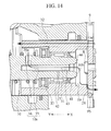
- a compressor according to the forth embodiment of the present invention is shown in Fig. 14.
- the compressor of the present embodiment differs from the compressor of the third embodiment in the provision of a ditch 43 of the axial passage 35.
- the inner peripheral surface of the axial passage 35 is provided with the ditch 43 extending straight from the rear end portion of the drive shaft 10 toward the front end portion thereof.
- the compressor of the present embodiment since the inner peripheral surface of the axial passage 35 is provided with the ditch 43, is largely captured within the ditch 43 oil flowing onto the inner peripheral surface. Oil captured within the ditch 43 is hard to be carried toward the downstream side X of the gas extraction passage 31 (the suction chamber 7 side) because that oil is hard to be affected by a dynamic pressure of the refrigerant gas flowing within the axial passage 35. Consequently, the amount of oil flowing out from the gas extraction passage 31 is further decreased.
- the compressor of this embodiment is formed to the ditch 43 an inlet portion of the oil supply passage 42, thereby the compressor of this embodiment has the advantage of an increase in the amount of oil flowing out from the oil supply passage 42 in comparison with that of the third embodiment.
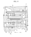
- a compressor according to the fifth embodiment of the present invention is shown in Fig. 15.
- the compressor of the present embodiment differs from the compressor of the forth embodiment in the configuration of the ditch 44.
- the ditch 44 is spirally formed on the inner peripheral surface of the axial passage 35.
- the present embodiment is formed to the ditch 44 the inlet portion of the oil supply passage 42 like the ditch 43 in the forth embodiment.
- the ditch 44 since the ditch 44 intersects the axial direction (the flow direction of the refrigerant gas), oil captured within the ditch 44 is further hard to be affected by the dynamic pressure of the refrigerant gas to be little carried toward the downstream side X. It amounts to this, that the ditch 44 acts like a resistant portion preventing oil from flowing toward the axial direction (the flow direction of the refrigerant gas).
- the ditch 44 is formed as screw ditch by a method in tapping on the surface thereof from a rear end opening 46 of the drive shaft 10.
- a compressor according to the sixth embodiment of the present invention is shown in Fig. 16.
- the compressor of the present embodiment differs from the compressor of the fifth embodiment in the provision of a bump surface 48 as the resistant portion.
- a bushing 47 is inserted into the axial passage 35 from the rear end opening 46 of the drive shaft 10 and fitted into the axial passage 35.
- a front end (the bump surface 48) of the bushing 47 is perpendicular to the axial direction (the flow direction of the refrigerant gas). Consequently, the bump surface 48 acts like a resistant portion preventing oil, being cable of flowing on the inner peripheral surface of the axial passage 35, from flowing toward the axial direction (the flow direction of the refrigerant gas). Therefore, the compressor of the present embodiment has an action effect like that of the compressor of the fifth embodiment.
- the drive shaft 10 is formed with the gas extraction passage 31, comprised of the axial passage 35 extending along the axis of the drive shaft 10, and the radial passage 36 perpendicularly connected to the axial passage 35 while forming the inlet portion of the gas extraction passage 31, directly exposed to the crank chamber 5, in the drive shaft 10 so as to radially extend, the amount of oil flowing out from the crank chamber 5 through the gas extraction passage 31 can be decreased in a simplified structure. Also, due to mist-like oil scattering from the inlet terminal end 36a of the radial passage 36 toward the crank chamber 5, oil can be automatically supplied to the sliding component parts within the crank chamber 5.
- the present invention includes a modification of the radial passage 36 shown in Fig. 7 to Fig. 11.
- a plurality of radial passages 36 may be provided to form associated inlet portions of the gas extraction passage 31.
- a plurality of radial passages 36 may be formed in the drive shaft10 at plural locations in parallel with respect to one another along the axial passage 35 of the drive shaft 10 and perpendicularly connected to the axial passage 35.
- a plurality of radial passages 36 extending toward an outer periphery of the drive shaft 10 from the axial passage 35 of the drive shaft 10.
- FIG. 8A a plurality of radial passages 36 extending toward an outer periphery of the drive shaft 10 from the axial passage 35 of the drive shaft 10.
- radial passages 36 may be perpendicularly connected to the axial passage 35 and extend through the drive shaft 10, and as shown in FIG. 8C, a plurality (i.e., three pieces in FIG. 8C) of radial passages 36 may be perpendicularly connected to the axial passage 35 and radially extend from the center of the drive shaft 10 toward the outer periphery thereof.
- the amount of refrigerant gas flowing into one radial passage 36 tends to decrease and, to that extent, oil is hard to be adversely affected by the gas stream passing through each radial passage 36, resulting in an advantage of centrifugal separating action being further effectively exhibited.
- radial passage 36 has been shown as being formed in the area displaced from the moveable range of the sleeve 22, in a particular case where the radial passage 36 has no choice but to be formed in the moveable range of the sleeve 22, as shown in FIG. 10, a plurality of radial passages 36 may be formed in the drive shaft 10 at axially spaced positions displaced from one another by a distance greater than an axial length d of the sleeve 22, with at least one of the radial passages 36 being configured to directly open to the crank chamber 5.
- the axial passage 35 may be formed in eccentric relation to the central axis of the drive shaft 10 provided that the radial passage 36 radially extends from the inlet terminal end 36a thereof toward the axial passage 35 so as to exhibit the centrifugal separating action.
- the radial passage 36 may be inclined with respect to the axial passage 35 and intersects the same. While the position at which the radial passage 36 is opened is limited to some extents, if it is structured such that, as shown in FIG.
- variable volume compressors of other types such as a wobble type
- the present invention may also be applied not only to the variable volume type but also to a fixed volume type compressor.
Landscapes
- Engineering & Computer Science (AREA)
- Mechanical Engineering (AREA)
- General Engineering & Computer Science (AREA)
- Compressor (AREA)
- Compressors, Vaccum Pumps And Other Relevant Systems (AREA)
Abstract

Description
- The present invention relates to a compressor adapted to be disposed in a refrigeration cycle, such as a vehicle air conditioning apparatus, for use in compression of refrigerant gas.
- In general, a compressor has a crank chamber in which lubricating oil is normally stored for the purpose of supplying lubricating oil to various sliding component parts disposed in the crank chamber. However, as disclosed in Japanese Patent Provisional Publication No. 62-203980, since the compressor of this type has an gas extraction passage that communicates with the crank chamber and a suction chamber, an issue arises in that lubricating oil flows from the crank chamber to the suction chamber through the gas extraction passage.
- If lubricating oil is carried from the crank chamber, the following two principal issues arise. First, if lubricating oil is carried from the crank chamber to result in shortage in oil to be supplied to the sliding component parts in the crank chamber, an adverse affect is caused in the sliding component parts. Second, if lubricating oil flows from the crank chamber into a heat exchanger (especially a condenser or an evaporator in the heat exchanger) in a refrigeration cycle through a path including the crank chamber→the suction chamber→the cylinder bore→the discharge chamber→ the compressor exterior→the heat exchanger, lubricating oil adheres to capillary tubes of the heat exchanger, resulting in deterioration in a heat exchange efficiency.
- In view of the above in mind, as disclosed in Japanese Patent Provisional Publication No. 58-158382, there is also a related art compressor with a structure wherein an outlet of an gas extraction passage is connected to a control valve that is expected to have the same function as an orifice. However, with the control valve of this related art technology, an opening and closing valve of the gas extraction passage is closed during an inoperative state of the compressor and, during operative state of the compressor, the opening and closing valve of the gas extraction passage is opened. As a result, even though oil is separated from gas, oil accompanied by gas flow is gradually flown out from a crank chamber too. Also, the presence of the control valve causes the gas extraction passage to be complicated in structure.
- It is therefore an object of the present invention to provide a compressor that is able to decrease an amount of oil flow escaping from a crank chamber through a gas extraction passage in a simplified structure.
- To achieve the above object, according to an aspect of the present invention, there is provided A compressor comprising: a cylinder block having a cylinder bore for accommodating a piston, bearings for supporting an end portion of a drive shaft, and a shaft support bore disposed between the bearings and a rear end of the cylinder block; a front housing attached to a front end of the cylinder block and formed with a crank chamber in which the piston is reciprocally moveable due to rotation of the drive shaft; and a rear housing attached to the rear end of the cylinder block via a valve plate and formed with a suction chamber and a discharge chamber therein, wherein a distal end portion of the drive shaft having a first gas extraction aperture is rotatably fitted in the shaft support bore attached to the valve plate having a second gas extraction aperture at rear end of the cylinder block, in the first gas extraction aperture, one opening end thereof being directly open to the crank chamber and the other opening end thereof being open to the shaft support bore, in the second gas extraction aperture, one opening end thereof being open to the shaft support bore and the other opening end thereof being open to the suction chamber.
- According to the present invention, the compressor features the provision of the gas extraction passage, establishing continuous communication between the crank chamber and the suction chamber, that has the inlet portion being directly open to the crank chamber in the drive shaft. With this structure, mist-like oil, accompanied by blow-by gas, tending to flow into the gas extraction passage initially impinges upon and is captured by an inner peripheral surface of the inlet portion of the gas extraction passage due to rotational movement of the drive shaft. That is, oil separation (gas-liquid separation) occurs at the inlet portion of the gas extraction passage. Then, oil separated from refrigeration gas at the inlet portion of the gas extraction passage is forced back to the crank chamber due to a centrifugal force caused by rotational movement of the drive shaft. Consequently, the compressor of the present invention has a structure in which oil is hard to escape into the suction chamber through the gas extraction passage. Since this results in a structure in that, even though the crank chamber continuously communicates with the suction chamber through the gas extraction passage without intervening the control valve, oil separation (gas-oil separation) positively occurs, it is possible to reduce an amount of oil, to be flown out from the crank chamber through the gas extraction passage, in a simplified structure.
-
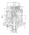
- FIG. 1 is an overall view of a compressor in the first embodiment according to the present invention.
- FIGS. 2A and 2Bare enlarged views illustrating an inlet side of a gas extraction passage of the compressor shown in FIG. 1.
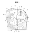
- FIG. 3 is an enlarged cross sectional view illustrating an outlet side of the gas extraction passage of the compressor shown in FIG. 1.
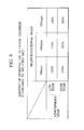
- FIG. 4 is a comparison view showing a flow restriction effect, for lubricating oil of the compressor shown in FIG. 1, in comparison with that of the related art structure.
- FIG. 5 is a view illustrating a cooling performance of the compressor shown in FIG. 1 in comparison with the related art structure in terms of a COP value.
- FIG. 6 is a view illustrating the cooling performance of the compressor shown in FIG. 1 in comparison with the related art structure in terms of a ventilation blow-off temperature.
- FIG. 7 is a view illustrating a modified form of a radial passage of the gas extraction passage of the compressor shown in FIG. 1.
- FIG. 8A is a view illustrating another modified form of the radial passage of the gas extraction passage of the compressor shown in FIG. 1.
- FIG. 8B is a cross sectional view illustrating one example of an inlet portion of the gas extraction passage of the compressor shown in FIG. 8A.
- FIG. 8C is a cross sectional view illustrating another example of an inlet portion of the gas extraction passage of the compressor shown in FIG. 8A.
- FIG. 9 is an overall view of a compressor having another modified radial passage of the gas extraction passage of the compressor shown in FIG.1.
- FIG. 10 is a cross sectional view of the modified radial passage shown in FIG. 9.
- FIG. 11 is a cross sectional view of a modification of the radial passage of the gas extraction passage of the compressor shown in FIG. 1.
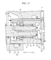
- FIG. 12 is a cross sectional view of substantial parts of a compressor in the second embodiment according to the present invention.
- FIG. 13 is a cross sectional view of substantial parts of a compressor in the third embodiment according to the present invention.
- FIG. 14 is a cross sectional view of substantial parts of a compressor in the forth embodiment according to the present invention.
- FIG. 15 is a cross sectional view of substantial parts of a compressor in the fifth embodiment according to the present invention.
- Fig. 16 is a cross sectional view of substantial parts of a compressor in the sixth embodiment according to the present invention.
-
- Hereinafter, embodiments of the present invention are described with reference to the drawings.
- As shown in FIG. 1, a
compressor 1 is of a swash plate type variable displacement compressor. The swash plate typevariable displacement compressor 1 is comprised of acylinder block 2 having a plurality ofcylinder bores 3, afront housing 4 attached to a front end of thecylinder block 2 and cooperating with thecylinder block 2 to define an air tight sealedcrank chamber 5, and arear housing 6 attached to a rear end of thecylinder block 2 via avalve plate 9 and including asuction chamber 7 and adischarge chamber 8. Further, thecylinder block 2, thefront housing 4 and therear housing 6 are fixedly connected to one another by means of a plurality of penetrating bolts B extending through a plurality of bolt-through-bores (not shown) formed in thecylinder block 2. - The
valve plate 9 is formed with a suction port (not shown) that communicates with thecylinder bore 3 and thesuction chamber 7, and adischarge port 12 that communicates with thecylinder bore 3 and thedischarge chamber 8. - As shown in FIG. 3, a
suction valve plate 13, made from a metallic sheet, is attached to thevalve plate 9 at one surface thereof closer to thecylinder block 2 and has a lead valve (not shown) adapted to open or close the suction port. On the other hand, disposed on thevalve plate 9 at the other surface thereof closer to therear housing 6 are adischarge valve plate 14, made from a metallic sheet, that has a lead valve (not shown) adapted to open or close thedischarge port 12, and aretainer 15 that retains thedischarge valve plate 14 in a fixed place and restricts an opening degree of the lead valve of thedischarge valve plate 14. Thevalve plate 9, thedischarge valve plate 14 and theretainer 15 are fixedly secured in a unitary structure. Also, agasket 16 is interposed between thevalve plate 9, at an other area than those where the above-described components are disposed, and therear housing 6 for providing an airtight sealing property between thesuction chamber 7 and thedischarge chamber 8. Moreover, an O-ring is disposed at an outer circumferential periphery of thevalve plate 9 to preclude refrigerant from leaking to the outside of thecompressor 1. - As shown in FIG. 1, centrally formed in the
cylinder block 2 and thefront housing 4 areshaft support bores bearings drive shaft 10 is rotatably supported. Especially, the bearing 17, 37 rotatably supports a rear end portion of thedrive shaft 10. - Disposed within the
crank chamber 5 are adrive plate 21 fixedly mounted on thedrive shaft 10 adjacent one of thecrank chamber 5, ajournal 24 connected through apin 23 to asleeve 22, for rocking movements, that is slidably disposed on thedrive shaft 10, and aswash plate 26 that is fixed to aboss segment 25 of thejournal 24. - The
drive plate 21 and thejournal 24 have hingearms elongated slot 27 and apin 28, thereby restricting rocking movements of theswash plate 26. Slidably disposed in each of thecylinder bores 3 is apiston 29 that is connected to theswash plate 26 through a pair ofshoes 30 by which theswash plate 26 is sandwiched, resulting in reciprocating movements of thepiston 29 based on motive power caused by rotational movement of thedrive shaft 10. Thus, thecompressor 1 has a basic function in that reciprocating movements of thepiston 29 sucks refrigerant in a path through thesuction chamber 7→the suction port of thevalve plate 9→the cylinder bore 3 and compresses sucked refrigerant whereupon compressed refrigerant is discharged in a path through the cylinder bore 3→the discharge port of thevalve plate 9→thedischarge chamber 8. - Further, in order to permit the
piston 29 to have a variable discharge volume, thecompressor 1 includes a pressure control mechanism which is comprised of a gas extraction passage 31 (as shown by an arrow in FIG. 1) that allows thecrank chamber 5 to continuously communicate with thesuction chamber 7, anair supply passage 32 through which thecrank chamber 5 communicates with the discharge chamber 8 (as shown by another arrow in FIG. 1), and a pressure control means 33 that opens or closes theair supply passage 32. Thegas extraction passage 31 serves to compel refrigerant gas in thecrank chamber 5 to be fed back to thesuction chamber 7 in dependence on refrigerant gas pressure within thecrank chamber 5. Theair supply passage 32 is opened or closed by the pressure control means 33 for thereby controlling a volume of refrigerant gas flowing from thedischarge chamber 8 to the crankchamber 5 to regulate pressure within thecrank chamber 5 such that an inclination angle of theswash plate 26 changes to vary a length of piston stroke to vary the discharge volume of thecompressor 1. More particularly, in order for an evaporator to be avoided from freezing during a low load, the pressure control means 33 is operative to vary the discharge volume of thecompressor 1 in dependence on a suction pressure of refrigerant fed back from thecompressor 1 such that theair supply passage 32 is controllably opened or closed in a way to maintain a suction pressure of refrigerant to be fed back to thecompressor 1 at a given level. - Now, the
gas extraction passage 31 is comprised of agas extraction aperture 10s formed in thedrive shaft 10, the shaft support bore 19 formed in thecylinder block 2, a gas extraction recess 2s formed in a rear distal end of thecylinder block 2, and agas extraction aperture 9s formed in thevalve plate 9. In thegas extraction aperture 10s, one opening end thereof is directly open to the crankchamber 5 and the other opening end thereof is open to the shaft support bore 19. In the gas extraction recess 2s, one opening end thereof is open to the shaft support bore 19 and the other opening end thereof is open to thegas extraction aperture 9s. In thegas extraction aperture 9s, one opening end thereof is open to the gas extraction recess 2s and the other opening end thereof is open to thesuction chamber 7. Therefore, thecrank chamber 5 continuously communicates with thesuction chamber 7 through the gas extraction passage 31 (see Fig. 1 and Fig. 3). Also, the gas extraction recess 2s forms a fixed restricting portion (orifice) that restricts an effective cross sectional area of thegas extraction passage 31 at a midway of thegas extraction passage 31. - Further, as shown in Fig. 2A, the
gas extraction aperture 10s formed in thedrive shaft 10 is formed by anaxial passage 35 formed in thedrive shaft 10 along a central axis thereof so as to extend straight from a reardistal end 10b to a frontdistal end 10a, and aradial passage 36 connected to theaxial passage 35 in a perpendicular direction thereto and directly opening to the crankchamber 5 to form an inlet portion of thegas extraction passage 31. Also, since theradial passage 36, that forms the inlet portion of thegas extraction passage 31, is formed in thedrive shaft 10 at an area displaced from a moveable range of thesleeve 22, theradial passage 36 is continuously open to the crankchamber 5. - With the
compressor 1 of the presently filed embodiment thus constructed, thegas extraction passage 31 is formed in thedrive shaft 10 to allow the crankchamber 5 and thesuction chamber 7 to continuously communicate with one another, and theradial passage 36 forming the inlet portion of thegas extraction passage 31 is directly exposed to the crankchamber 5. As a result, as shown in FIG. 2A, mist-like oil accompanied by refrigerant gas flowing out from thecrank chamber 5 into thegas extraction passage 31 is caused to impinge upon an inner periphery of theradial passage 36 and captured thereto due to rotational movement of thedrive shaft 10. That is, within theradial passage 36 forming the inlet portion of thegas extraction passage 31, separation of oil (gas-liquid separation) occurs. Subsequently, as shown in FIG. 2B, oil adhered to theradial passage 36 is forced back to an inletterminal end 36a of theradial passage 36 by a centrifugal force caused by rotational movement of thedrive shaft 10 and discharged into thecrank chamber 5 remaining separate from refrigerant gas. - As a result of oil being separated and forced back to the crank
chamber 5, a structure is provided in which oil is hard to escape to thesuction chamber 7 through thegas extraction passage 31, resulting in reduction in a flow rate of oil escaping outward through the oilgas extraction passage 31. Also, the presence of oil scattering toward thecrank chamber 5 from the inletterminal end 36a of theradial passage 36 enables oil to be automatically supplied to sliding component parts disposed in thecrank chamber 5. - In this connection, Japanese Patent Provisional Publication No. 58-158382 discloses a compressor provided with a gas extraction bore formed in a drive shaft to include an axial passage and a radial passage. Even in this compressor, a centrifugal separating action is expected to occur due to the axial passage.
- However, this compressor has a structure in that the radial passage is closed by a sleeve in the first place while a gap between the sleeve and the drive shaft is formed with an inlet portion as a part of the gas extraction bore whereupon oil is supplied to a space between the sleeve and the drive shaft in a path along a stream of gas flow. As a result, oil, that has entered the space between the sleeve and the drive shaft once, is hard to be discharged from that space and adversely affected with gas flow to be finally delivered to a suction chamber.
- On the contrary, with the presently filed embodiment, since the
radial passage 36 forming the inlet portion of thegas extraction passage 31 is directly open to the crankchamber 5, oil is forced back to the inletterminal end 36a of theradial passage 36 due to the centrifugal force of thedrive shaft 10 in a manner set forth above and directly discharged into thecrank chamber 5. Accordingly, the centrifugal separating action can be utilized with no waste, thereby enabling reduction in the amount of oil escaping from thecrank chamber 5 through thegas extraction passage 31 in a simplified structure. Also, the presence of oil scattering toward thecrank chamber 5 from the inletterminal end 36a of theradial passage 36 enables oil to be automatically supplied to the sliding component parts disposed within thecrank chamber 5. - With the presently filed embodiment, further, since the
radial passage 36, forming the inlet portion of thegas extraction passage 31, is formed in thedrive shaft 10 at the area displaced from the moveable range of thesleeve 22 effectuated depending on the discharge volume to be altered, it is not possible that theradial passage 36 is closed by thesleeve 22. - In actual practice, a lubricating oil flow-out restriction effect was conducted after the compressor of the presently filed embodiment had been operated for 0.5 hours, with test results being shown in FIG. 4 that shows the
compressor 1 of the presently filed embodiment has larger increased amounts of residual oil remaining in thecrank chamber 5 than those of the related art compressor. Here, observing differences among the amounts of remaining oil in terms of the rotational speed, it becomes clear that the larger the rotational speed, the higher will be the oil flow-out restricting effect. This is due to the fact that as the rotational speed of thedrive shaft 10 increases, the centrifugal separating action acting on theradial passage 36 increases. Moreover, observing a difference in the amounts of remaining oil in terms of the atmospheric temperature, it appears that the higher the atmospheric temperature, the higher will be the oil flow-out restricting effect. This is due to the fact that as the atmospheric temperature increases, a thermal load increases to cause the compressor to operate under an increased discharge volume with a resultant increase in blow-by gas for thereby increasing the amount of refrigerant gas to be fed back from thecrank chamber 5 to thesuction chamber 7 through thegas extraction passage 31. - Further, upon conducting an actual on-vehicle refrigeration power test for a refrigeration cycle using the
compressor 1 with the oil flow-out restricting effect set forth above, as shown in FIG. 5, a COP value (= a cooling performance [W] / power [W]) of the present embodiment had a 9 % increase in improvement higher than that of the prior art in terms of a cooled down condition for three minutes and a 12 % increase in improvement higher than that of the prior art in terms of an idling condition for twenty minutes. Likewise, as shown in FIG. 6, the present embodiment achieved a lower ventilation blow-off temperature, appearing under the conditions set forth above, lower than the prior art by 1.8 degree C in terms of the cooled down condition for three minutes and the lower ventilation blow-off temperature lower than the prior art by 1.5 degree C in terms of the idling condition for twenty minutes. Also, the actual refrigeration power test means the cooling capacity test of the refrigerating cycle, based on a rule defined by the present company to which the applicant belongs, with the cooling power test being conducted under a condition in which an actual vehicle is driven at a speed of 40 [km/h] for thirty minutes and subsequently driven at a speed of 100 [km/h] under the cooled down condition for twenty minutes whereupon the vehicle is driven under the idling condition for twenty minutes. - Thus, in the refrigeration cycle using the
compressor 1 of the presently filed embodiment, due to reduction in the amount of oil to be flown out from thecompressor 1 in a manner described above, it is possible to reduce the amount of oil to enter a heat exchanger (involving a condenser or an evaporator therein) in the refrigeration cycle. That is, the presence of reduction in the amount of oil that adheres to capillary tubes of he heat exchanger provides an improvement over the cooling performance of the refrigeration cycle. Also, the test results of the related art shown in Figs. 4 to 6 corresponds to those of the compressor that utilizes the through-bore of thecylinder block 2 as a gas extraction passage. - A compressor according to the second embodiment of the present invention is shown in Fig. 12. It is noted that the compressor shown in Fig.12 has the same parts as the compressor according to the first embodiment, and like parts are designed by like numbers and details thereof are omitted.
- The compressor of the present embodiment differs from the compressor of the first embodiment in the provision of a seal member. A
lip seal 41 as the seal member is attached to thedrive shaft 10 to seal a gap between an inner peripheral surface of the shaft support bore 19 and an outer peripheral surface of thedrive shaft 10. - According to the compressor of the present embodiment, the amount of oil flowing out from the
crank chamber 5 can be further decreased by a seal action of thelip seal 41. Specifically, although it is possible that the refrigerant gas within thecrank chamber 5, as shown by an imaginary line in Fig. 11, by-passes thegas extraction aperture 10s (35, 36) and passes through thebearings drive shaft 10 toward the downstream side X of thegas extraction passage 31, thelip seal 41 prevents the refrigerant gas accompanying oil from by-passing thegas extraction aperture 10s. Consequently, is decreased the amount of oil flowing out from thecrank chamber 5. - Here, since the
lip seal 41 is attached to thedrive shaft 10 at a surface thereof closer to therear housing 6 than to thebearings 17, 37 (that is, at the downstream side X of the gas extraction passage 31), oil stored in thecrank chamber 5 is supplied to thesebearings - Hereinafter, preferred embodiments are further described, and if a compressor of each preferred embodiment has the same parts as the compressor according to the first embodiment and the second embodiment, like parts are designed by like numbers and details thereof are omitted.
- A compressor according to the third embodiment of the present invention is shown in Fig. 13. The compressor of the present embodiment differs from the compressor of the second embodiment in the provision of an
oil supply passage 42. One end of theoil supply passage 42 is connected to theaxial passage 35 as theoil supply passage 42 communicates with theaxial passage 35, and the other end thereof is directly open to thebearing 17. - Therefore, in the compressor of the present embodiment, the bearing 17 being one of the sliding component parts can be supplied with oil having flowed into the
axial passage 35 to be adhered to an inner peripheral surface of theaxial passage 35 due to a centrifugal force. As a result, an endurance of thebearing 17 improves in this provision. - Moreover, according to the present invention, since this
oil supply passage 42 is directly open to the space around the bearing 17 closer to the crankchamber 5 than to thelip seal 41, oil discharged from theoil supply passage 42 exits in that space. It amounts to this, that is further decreased the amount of oil flowing out from thecrank chamber 5 because oil having once flowed into theaxial passage 35 is discharged into the space around the bearing 17 closer to the crankchamber 5. - A compressor according to the forth embodiment of the present invention is shown in Fig. 14. The compressor of the present embodiment differs from the compressor of the third embodiment in the provision of a
ditch 43 of theaxial passage 35. The inner peripheral surface of theaxial passage 35 is provided with theditch 43 extending straight from the rear end portion of thedrive shaft 10 toward the front end portion thereof. - According to the compressor of the present embodiment, since the inner peripheral surface of the
axial passage 35 is provided with theditch 43, is largely captured within theditch 43 oil flowing onto the inner peripheral surface. Oil captured within theditch 43 is hard to be carried toward the downstream side X of the gas extraction passage 31 (thesuction chamber 7 side) because that oil is hard to be affected by a dynamic pressure of the refrigerant gas flowing within theaxial passage 35. Consequently, the amount of oil flowing out from thegas extraction passage 31 is further decreased. Here, in the present embodiment, is formed to theditch 43 an inlet portion of theoil supply passage 42, thereby the compressor of this embodiment has the advantage of an increase in the amount of oil flowing out from theoil supply passage 42 in comparison with that of the third embodiment. - A compressor according to the fifth embodiment of the present invention is shown in Fig. 15. The compressor of the present embodiment differs from the compressor of the forth embodiment in the configuration of the
ditch 44. Theditch 44 is spirally formed on the inner peripheral surface of theaxial passage 35. Here, in the present embodiment, is formed to theditch 44 the inlet portion of theoil supply passage 42 like theditch 43 in the forth embodiment. - According to the compressor of the present embodiment, in addition to the advantage of the forth embodiment, since the
ditch 44 intersects the axial direction (the flow direction of the refrigerant gas), oil captured within theditch 44 is further hard to be affected by the dynamic pressure of the refrigerant gas to be little carried toward the downstream side X. It amounts to this, that theditch 44 acts like a resistant portion preventing oil from flowing toward the axial direction (the flow direction of the refrigerant gas). - Even in this
ditch 44, it is expected to occur an action for pushing back oil to theradial passage 36 positioned at an upstream side Y of thegas extraction passage 31. Here, for example, theditch 44 is formed as screw ditch by a method in tapping on the surface thereof from a rear end opening 46 of thedrive shaft 10. - A compressor according to the sixth embodiment of the present invention is shown in Fig. 16. The compressor of the present embodiment differs from the compressor of the fifth embodiment in the provision of a
bump surface 48 as the resistant portion. Abushing 47 is inserted into theaxial passage 35 from the rear end opening 46 of thedrive shaft 10 and fitted into theaxial passage 35. Thereby, a front end (the bump surface 48) of thebushing 47 is perpendicular to the axial direction (the flow direction of the refrigerant gas). Consequently, thebump surface 48 acts like a resistant portion preventing oil, being cable of flowing on the inner peripheral surface of theaxial passage 35, from flowing toward the axial direction (the flow direction of the refrigerant gas). Therefore, the compressor of the present embodiment has an action effect like that of the compressor of the fifth embodiment. - According to the first to the sixth embodiments of present invention, since the
drive shaft 10 is formed with thegas extraction passage 31, comprised of theaxial passage 35 extending along the axis of thedrive shaft 10, and theradial passage 36 perpendicularly connected to theaxial passage 35 while forming the inlet portion of thegas extraction passage 31, directly exposed to the crankchamber 5, in thedrive shaft 10 so as to radially extend, the amount of oil flowing out from thecrank chamber 5 through thegas extraction passage 31 can be decreased in a simplified structure. Also, due to mist-like oil scattering from the inletterminal end 36a of theradial passage 36 toward thecrank chamber 5, oil can be automatically supplied to the sliding component parts within thecrank chamber 5. - Moreover, the present invention includes a modification of the
radial passage 36 shown in Fig. 7 to Fig. 11. Specifically, according to the present invention, a plurality ofradial passages 36 may be provided to form associated inlet portions of thegas extraction passage 31. In particular, as shown in FIG. 7, a plurality ofradial passages 36 may be formed in the drive shaft10 at plural locations in parallel with respect to one another along theaxial passage 35 of thedrive shaft 10 and perpendicularly connected to theaxial passage 35. Also, as shown in FIG. 8A, a plurality ofradial passages 36 extending toward an outer periphery of thedrive shaft 10 from theaxial passage 35 of thedrive shaft 10. In particular, as shown in FIG. 8B,radial passages 36 may be perpendicularly connected to theaxial passage 35 and extend through thedrive shaft 10, and as shown in FIG. 8C, a plurality (i.e., three pieces in FIG. 8C) ofradial passages 36 may be perpendicularly connected to theaxial passage 35 and radially extend from the center of thedrive shaft 10 toward the outer periphery thereof. Thus, when formed with the plurality ofradial passages 36, as shown in Fig. 9, the amount of refrigerant gas flowing into oneradial passage 36 tends to decrease and, to that extent, oil is hard to be adversely affected by the gas stream passing through eachradial passage 36, resulting in an advantage of centrifugal separating action being further effectively exhibited. - Further, with the embodiments described above, although the
radial passage 36 has been shown as being formed in the area displaced from the moveable range of thesleeve 22, in a particular case where theradial passage 36 has no choice but to be formed in the moveable range of thesleeve 22, as shown in FIG. 10, a plurality ofradial passages 36 may be formed in thedrive shaft 10 at axially spaced positions displaced from one another by a distance greater than an axial length d of thesleeve 22, with at least one of theradial passages 36 being configured to directly open to the crankchamber 5. - Furthermore, according to the present invention, the
axial passage 35 may be formed in eccentric relation to the central axis of thedrive shaft 10 provided that theradial passage 36 radially extends from the inletterminal end 36a thereof toward theaxial passage 35 so as to exhibit the centrifugal separating action. Moreover, as shown in FIG. 11, theradial passage 36 may be inclined with respect to theaxial passage 35 and intersects the same. While the position at which theradial passage 36 is opened is limited to some extents, if it is structured such that, as shown in FIG. 11, if the inletterminal end 36a is inclined so as to be oriented toward the sliding component parts (i.e., a sliding area between a shoe pocket and a shoe, and a sliding area between the shoe and the swash plate), oil scattering utilizing the centrifugal force occurs with a resultant capability of permitting oil to be more positively supplied to the sliding component parts. - Further, while the above described embodiments has been shown as including the swash type
variable displacement compressor 1, the present invention may also be applied to variable volume compressors of other types such as a wobble type and, of course, may also be applied not only to the variable volume type but also to a fixed volume type compressor.
Claims (13)
- A compressor (1) comprising:wherein a distal end portion (10b) of the drive shaft (10) having a first gas extraction aperture (10s) is rotatably fitted in the shaft support bore (19) attached to the valve plate (9) having a second gas extraction aperture (9s) at rear end of the cylinder block (2),a cylinder block (2) having a cylinder bore (3) for accommodating a piston (29), bearings (17, 37) for supporting an end portion of a drive shaft (10), and a shaft support bore (19) disposed between the bearings (17, 37) and a rear end of the cylinder block (2);a front housing (4) attached to a front end of the cylinder block (2) and formed with a crank chamber (5) in which the piston (29) is reciprocally moveable due to rotation of the drive shaft (10); anda rear housing (6) attached to the rear end of the cylinder block (2) via a valve plate (9) and formed with a suction chamber (7) and a discharge chamber (8) therein,
in the first gas extraction aperture (10s), one opening end thereof being directly open to the crank chamber (5) and the other opening end thereof being open to the shaft support bore (19),
in the second gas extraction aperture (9s), one opening end thereof being open to the shaft support bore (19) and the other opening end thereof being open to the suction chamber (7). - The compressor (1) according to claim 1, wherein there is a gas extraction recess (2s) at a rear distal end of the cylinder block (2) and, in the gas extraction recess (2s), one opening end thereof is open to the shaft support bore (19) and the other opening end thereof is open to the second gas extraction aperture (9s).
- The compressor (1) according to claim 1, wherein a seal member (41) is attached to the drive shaft (10) to seal a gap between the shaft support bore (19) and the drive shaft (10).
- The compressor (1) according to claim 3, wherein the seal member (41) is attached to the drive shaft (10) at a surface thereof closer to the rear housing (6) than to the bearings (17, 37).
- The compressor (1) according to claim 4, wherein an oil supply passage (42) is formed in the drive shaft (10), one opening end of the oil supply passage (42) being open to the first gas extraction aperture (10s) and the other opening end thereof being open to the bearing (17).
- The compressor (1) according to claim 1, wherein the first gas extraction aperture (10s) includes an axial passage (35) formed in the drive shaft (10) along a central axis thereof and a radial passage (36) connected to the axial passage (35) and formed in the drive shaft (10) along a radial direction, one opening end of the radial passage (36) being directly open to the crank chamber (5).
- The compressor (1) according to claim 6, wherein a resistant portion (44, 48) is formed in the axis passage (35) and prevents oil being cable of flowing on an inner peripheral surface of the axis passage (35) from flowing toward the axial direction (X).
- The compressor (1) according to claim 6, wherein a ditch (43, 44) is formed on an inner peripheral surface of the axis passage (35).
- The compressor (1) according to claim 8, wherein the ditch (44) is spirally formed on the inner peripheral surface of the axial passage (35).
- The compressor (1) according to claim 6, wherein the radial passage (36) extends through the drive shaft (10).
- The compressor (1) according to claim 6, wherein the radial passage (36) includes a plurality of passage components that are formed in the drive shaft (10) along the axial passage (35) to extend in parallel with respect one another.
- The compressor (1) according to claim 6, wherein the radial passage (36) includes a plurality of passage components that radially extend from the axial passage (35) toward an outer periphery of the drive shaft (10).
- The compressor (1) according to claim 6, wherein the radial passage (36) is connected to the axial passage (35) at an inclined angle with respect thereto.
Applications Claiming Priority (4)
| Application Number | Priority Date | Filing Date | Title |
|---|---|---|---|
| JP2002078730 | 2002-03-20 | ||
| JP2002078730 | 2002-03-20 | ||
| JP2003056101 | 2003-03-03 | ||
| JP2003056101A JP4078229B2 (en) | 2002-03-20 | 2003-03-03 | Compressor |
Publications (3)
| Publication Number | Publication Date |
|---|---|
| EP1347173A2 true EP1347173A2 (en) | 2003-09-24 |
| EP1347173A3 EP1347173A3 (en) | 2003-12-10 |
| EP1347173B1 EP1347173B1 (en) | 2007-05-16 |
Family
ID=27791040
Family Applications (1)
| Application Number | Title | Priority Date | Filing Date |
|---|---|---|---|
| EP03006250A Expired - Lifetime EP1347173B1 (en) | 2002-03-20 | 2003-03-20 | Lubrication system for swash plate compressor |
Country Status (5)
| Country | Link |
|---|---|
| US (1) | US6942465B2 (en) |
| EP (1) | EP1347173B1 (en) |
| JP (1) | JP4078229B2 (en) |
| KR (1) | KR20030076352A (en) |
| DE (1) | DE60313819T2 (en) |
Cited By (4)
| Publication number | Priority date | Publication date | Assignee | Title |
|---|---|---|---|---|
| EP1744059A1 (en) * | 2005-07-15 | 2007-01-17 | Kabushiki Kaisha Toyota Jidoshokki | Variable displacement compressor |
| EP1840374A3 (en) * | 2006-03-29 | 2009-08-12 | Valeo Compressor Europe GmbH | Compressor |
| EP1933031A3 (en) * | 2006-12-07 | 2011-01-19 | Kabushiki Kaisha Toyota Jidoshokki | Variable displacement compressor |
| EP2067994A3 (en) * | 2007-12-06 | 2011-05-11 | Calsonic Kansei Corporation | Tilting plate type compressor |
Families Citing this family (27)
| Publication number | Priority date | Publication date | Assignee | Title |
|---|---|---|---|---|
| JP2005194932A (en) * | 2004-01-07 | 2005-07-21 | Zexel Valeo Climate Control Corp | Variable displacement compressor |
| JP2006022785A (en) * | 2004-07-09 | 2006-01-26 | Toyota Industries Corp | Variable capacity compressor |
| JP2006046115A (en) * | 2004-08-02 | 2006-02-16 | Calsonic Kansei Corp | Oil separator structure of compressor |
| JP2006132423A (en) * | 2004-11-05 | 2006-05-25 | Calsonic Kansei Corp | Compressor |
| JP4766928B2 (en) * | 2005-06-09 | 2011-09-07 | サンデン株式会社 | Refrigerant gas compressor |
| JP4642574B2 (en) * | 2005-07-07 | 2011-03-02 | サンデン株式会社 | Reciprocating compressor |
| JP4826948B2 (en) * | 2005-10-06 | 2011-11-30 | 株式会社ヴァレオジャパン | Piston type compressor |
| KR101065930B1 (en) | 2006-07-27 | 2011-09-19 | 한라공조주식회사 | compressor |
| JP4684186B2 (en) * | 2006-08-29 | 2011-05-18 | カルソニックカンセイ株式会社 | Variable capacity compressor |
| US7520210B2 (en) * | 2006-09-27 | 2009-04-21 | Visteon Global Technologies, Inc. | Oil separator for a fluid displacement apparatus |
| JP4345807B2 (en) * | 2006-12-13 | 2009-10-14 | 株式会社豊田自動織機 | Capacity control structure in variable capacity compressor |
| US8038415B2 (en) * | 2007-06-01 | 2011-10-18 | Halla Climate Control Corp. | Variable capacity swash plate type compressor |
| JP4505482B2 (en) | 2007-06-27 | 2010-07-21 | カルソニックカンセイ株式会社 | Compressor |
| EP2017476A2 (en) * | 2007-07-18 | 2009-01-21 | Calsonic Kansei Corporation | Compressor |
| JP2009108750A (en) * | 2007-10-30 | 2009-05-21 | Valeo Thermal Systems Japan Corp | Piston-type compressor |
| KR100887231B1 (en) * | 2007-11-22 | 2009-03-06 | 학교법인 두원학원 | Capacity variable compressor with drive shaft refrigerant flow |
| JP4924464B2 (en) * | 2008-02-05 | 2012-04-25 | 株式会社豊田自動織機 | Swash plate compressor |
| JP5076998B2 (en) * | 2008-03-21 | 2012-11-21 | アイシン精機株式会社 | Water pump |
| JP5218905B2 (en) * | 2008-09-24 | 2013-06-26 | 株式会社ヴァレオジャパン | Variable capacity swash plate compressor |
| US8348632B2 (en) * | 2009-11-23 | 2013-01-08 | Denso International America, Inc. | Variable displacement compressor shaft oil separator |
| US9163620B2 (en) * | 2011-02-04 | 2015-10-20 | Halla Visteon Climate Control Corporation | Oil management system for a compressor |
| WO2015199207A1 (en) * | 2014-06-27 | 2015-12-30 | 株式会社ヴァレオジャパン | Variable displacement swash plate compressor |
| KR102717000B1 (en) | 2019-01-08 | 2024-10-15 | 한온시스템 주식회사 | Compressor |
| US12345246B2 (en) | 2020-09-02 | 2025-07-01 | Valeo Japan Co., Ltd. | Variable-displacement swash plate type compressor |
| KR102793086B1 (en) * | 2021-11-17 | 2025-04-09 | 에스트라오토모티브시스템 주식회사 | Variable swash plate compressor with variable refrigerant drain structure in response to amount of stroke of swashplate |
| KR102722415B1 (en) | 2022-10-06 | 2024-10-25 | 에스트라오토모티브시스템 주식회사 | Variable swash plate compressor |
| KR102793088B1 (en) | 2022-10-06 | 2025-04-09 | 에스트라오토모티브시스템 주식회사 | Variable swash plate compressor |
Citations (2)
| Publication number | Priority date | Publication date | Assignee | Title |
|---|---|---|---|---|
| JPS58158382A (en) | 1982-02-25 | 1983-09-20 | ゼネラル・モ−タ−ズ・コ−ポレ−シヨン | Displacement variable compressor |
| JPS62203980A (en) | 1986-03-03 | 1987-09-08 | Toyoda Autom Loom Works Ltd | Mechanism for controlling wobbling angle of wobble plate in wobble plate type compressor |
Family Cites Families (18)
| Publication number | Priority date | Publication date | Assignee | Title |
|---|---|---|---|---|
| JPS58158177U (en) * | 1982-04-19 | 1983-10-21 | 三輪精機株式会社 | Compressor lubricating oil collection device |
| JPH037584Y2 (en) * | 1986-08-01 | 1991-02-25 | ||
| US5181834A (en) * | 1991-07-26 | 1993-01-26 | Kabushiki Kaisha Toyoda Jidoshokii Seisakusho | Swash plate type compressor |
| JPH0599136A (en) * | 1991-10-23 | 1993-04-20 | Sanden Corp | Variable capacity type swash plate type compressor |
| JP3088536B2 (en) * | 1991-12-26 | 2000-09-18 | サンデン株式会社 | Variable displacement oscillating compressor |
| JPH05231309A (en) * | 1992-02-20 | 1993-09-07 | Toyota Autom Loom Works Ltd | Lubrication structure in piston type compressor |
| JPH06123280A (en) * | 1992-10-08 | 1994-05-06 | Toyota Autom Loom Works Ltd | Reciprocating compressor |
| JPH06299956A (en) * | 1993-04-13 | 1994-10-25 | Toyota Autom Loom Works Ltd | Refrigerant gas intake structure in piston type compressor |
| JPH0960584A (en) * | 1995-08-21 | 1997-03-04 | Toyota Autom Loom Works Ltd | Variable capacity compressor |
| JPH10148177A (en) * | 1996-11-20 | 1998-06-02 | Toyota Autom Loom Works Ltd | Variable displacement compressor |
| JP3564929B2 (en) * | 1997-03-31 | 2004-09-15 | 株式会社豊田自動織機 | Compressor |
| JPH11287181A (en) * | 1998-04-02 | 1999-10-19 | Toyota Autom Loom Works Ltd | Variable capacity compressor |
| JP2000283028A (en) * | 1999-03-26 | 2000-10-10 | Toyota Autom Loom Works Ltd | Variable displacement compressor |
| JP2002070729A (en) * | 2000-06-13 | 2002-03-08 | Toyota Industries Corp | Swash plate compressor |
| JP2002013474A (en) * | 2000-06-28 | 2002-01-18 | Toyota Industries Corp | Variable capacity compressor |
| JP2002031043A (en) * | 2000-07-14 | 2002-01-31 | Toyota Industries Corp | Compressor |
| JP4399994B2 (en) * | 2000-11-17 | 2010-01-20 | 株式会社豊田自動織機 | Variable capacity compressor |
| US6786703B2 (en) * | 2001-11-02 | 2004-09-07 | Delphi Technologies, Inc. | Variable capacity air conditioning compressor with improved crankcase oil retention |
-
2003
- 2003-03-03 JP JP2003056101A patent/JP4078229B2/en not_active Expired - Fee Related
- 2003-03-19 US US10/391,207 patent/US6942465B2/en not_active Expired - Fee Related
- 2003-03-19 KR KR10-2003-0016971A patent/KR20030076352A/en not_active Ceased
- 2003-03-20 EP EP03006250A patent/EP1347173B1/en not_active Expired - Lifetime
- 2003-03-20 DE DE60313819T patent/DE60313819T2/en not_active Expired - Fee Related
Patent Citations (2)
| Publication number | Priority date | Publication date | Assignee | Title |
|---|---|---|---|---|
| JPS58158382A (en) | 1982-02-25 | 1983-09-20 | ゼネラル・モ−タ−ズ・コ−ポレ−シヨン | Displacement variable compressor |
| JPS62203980A (en) | 1986-03-03 | 1987-09-08 | Toyoda Autom Loom Works Ltd | Mechanism for controlling wobbling angle of wobble plate in wobble plate type compressor |
Cited By (4)
| Publication number | Priority date | Publication date | Assignee | Title |
|---|---|---|---|---|
| EP1744059A1 (en) * | 2005-07-15 | 2007-01-17 | Kabushiki Kaisha Toyota Jidoshokki | Variable displacement compressor |
| EP1840374A3 (en) * | 2006-03-29 | 2009-08-12 | Valeo Compressor Europe GmbH | Compressor |
| EP1933031A3 (en) * | 2006-12-07 | 2011-01-19 | Kabushiki Kaisha Toyota Jidoshokki | Variable displacement compressor |
| EP2067994A3 (en) * | 2007-12-06 | 2011-05-11 | Calsonic Kansei Corporation | Tilting plate type compressor |
Also Published As
| Publication number | Publication date |
|---|---|
| EP1347173B1 (en) | 2007-05-16 |
| JP4078229B2 (en) | 2008-04-23 |
| US6942465B2 (en) | 2005-09-13 |
| KR20030076352A (en) | 2003-09-26 |
| DE60313819D1 (en) | 2007-06-28 |
| DE60313819T2 (en) | 2007-10-11 |
| EP1347173A3 (en) | 2003-12-10 |
| JP2003343440A (en) | 2003-12-03 |
| US20040005223A1 (en) | 2004-01-08 |
Similar Documents
| Publication | Publication Date | Title |
|---|---|---|
| US6942465B2 (en) | Compressor | |
| US6558133B2 (en) | Variable displacement compressor | |
| KR19980063912A (en) | Variable capacity compressor | |
| EP0738832B1 (en) | Lubricating mechanism for piston type compressor | |
| US5842834A (en) | Swash plate type compressor employing single-headed pistons | |
| JP2000080983A (en) | Compressor | |
| EP0926346A2 (en) | Compressor | |
| US4236876A (en) | Multiple compressor system | |
| JP4258132B2 (en) | Rotary multistage compressor | |
| JPH10311277A (en) | Refrigerant compressor | |
| US6793464B2 (en) | Motor-driven compressor cooled by refrigerant gas | |
| US6192699B1 (en) | Variable capacity compressor | |
| KR20000047339A (en) | Oil separator including compressor | |
| JP3216343B2 (en) | Reciprocating compressor | |
| JP2008050963A (en) | Gas compressor | |
| US6481979B2 (en) | Lubrication passage and nozzle for swash plate type compressor | |
| JP3632448B2 (en) | Compressor | |
| US5167492A (en) | Fluid pumping assembly having a lubrication circuit functioning independent of the orientation of the fluid pumping assembly | |
| US9797638B2 (en) | Compressor | |
| KR102130406B1 (en) | Compressor | |
| FR2845432A1 (en) | AXIAL CO2 PISTON COMPRESSOR FOR AIR CONDITIONING SYSTEMS OF MOTOR VEHICLES | |
| CN112610497B (en) | Stirring structure, compressor and air conditioning system | |
| JP2004084633A (en) | Oil return control device for gas compressor | |
| JPH01219364A (en) | Variable displacement type swash plate compressor | |
| JP2004218565A (en) | Variable displacement swash plate compressor |
Legal Events
| Date | Code | Title | Description |
|---|---|---|---|
| PUAI | Public reference made under article 153(3) epc to a published international application that has entered the european phase |
Free format text: ORIGINAL CODE: 0009012 |
|
| AK | Designated contracting states |
Kind code of ref document: A2 Designated state(s): AT BE BG CH CY CZ DE DK EE ES FI FR GB GR HU IE IT LI LU MC NL PT RO SE SI SK TR |
|
| AX | Request for extension of the european patent |
Extension state: AL LT LV MK |
|
| PUAL | Search report despatched |
Free format text: ORIGINAL CODE: 0009013 |
|
| AK | Designated contracting states |
Kind code of ref document: A3 Designated state(s): AT BE BG CH CY CZ DE DK EE ES FI FR GB GR HU IE IT LI LU MC NL PT RO SE SI SK TR |
|
| AX | Request for extension of the european patent |
Extension state: AL LT LV MK |
|
| 17P | Request for examination filed |
Effective date: 20040122 |
|
| 17Q | First examination report despatched |
Effective date: 20040426 |
|
| AKX | Designation fees paid |
Designated state(s): DE FR GB |
|
| GRAP | Despatch of communication of intention to grant a patent |
Free format text: ORIGINAL CODE: EPIDOSNIGR1 |
|
| GRAS | Grant fee paid |
Free format text: ORIGINAL CODE: EPIDOSNIGR3 |
|
| GRAA | (expected) grant |
Free format text: ORIGINAL CODE: 0009210 |
|
| AK | Designated contracting states |
Kind code of ref document: B1 Designated state(s): DE FR GB |
|
| REG | Reference to a national code |
Ref country code: GB Ref legal event code: FG4D |
|
| REF | Corresponds to: |
Ref document number: 60313819 Country of ref document: DE Date of ref document: 20070628 Kind code of ref document: P |
|
| ET | Fr: translation filed | ||
| PLBE | No opposition filed within time limit |
Free format text: ORIGINAL CODE: 0009261 |
|
| STAA | Information on the status of an ep patent application or granted ep patent |
Free format text: STATUS: NO OPPOSITION FILED WITHIN TIME LIMIT |
|
| 26N | No opposition filed |
Effective date: 20080219 |
|
| PGFP | Annual fee paid to national office [announced via postgrant information from national office to epo] |
Ref country code: GB Payment date: 20090318 Year of fee payment: 7 |
|
| PGFP | Annual fee paid to national office [announced via postgrant information from national office to epo] |
Ref country code: DE Payment date: 20090313 Year of fee payment: 7 |
|
| REG | Reference to a national code |
Ref country code: GB Ref legal event code: 746 Effective date: 20090924 |
|
| PGFP | Annual fee paid to national office [announced via postgrant information from national office to epo] |
Ref country code: FR Payment date: 20090316 Year of fee payment: 7 |
|
| GBPC | Gb: european patent ceased through non-payment of renewal fee |
Effective date: 20100320 |
|
| REG | Reference to a national code |
Ref country code: FR Ref legal event code: ST Effective date: 20101130 |
|
| PG25 | Lapsed in a contracting state [announced via postgrant information from national office to epo] |
Ref country code: FR Free format text: LAPSE BECAUSE OF NON-PAYMENT OF DUE FEES Effective date: 20100331 |
|
| PG25 | Lapsed in a contracting state [announced via postgrant information from national office to epo] |
Ref country code: DE Free format text: LAPSE BECAUSE OF NON-PAYMENT OF DUE FEES Effective date: 20101001 |
|
| PG25 | Lapsed in a contracting state [announced via postgrant information from national office to epo] |
Ref country code: GB Free format text: LAPSE BECAUSE OF NON-PAYMENT OF DUE FEES Effective date: 20100320 |