EP1347142B1 - Process and device for mechanically applying a spacer ribbon onto a glass pane - Google Patents
Process and device for mechanically applying a spacer ribbon onto a glass pane Download PDFInfo
- Publication number
- EP1347142B1 EP1347142B1 EP03003854A EP03003854A EP1347142B1 EP 1347142 B1 EP1347142 B1 EP 1347142B1 EP 03003854 A EP03003854 A EP 03003854A EP 03003854 A EP03003854 A EP 03003854A EP 1347142 B1 EP1347142 B1 EP 1347142B1
- Authority
- EP
- European Patent Office
- Prior art keywords
- band
- rollers
- pair
- application
- compensating section
- Prior art date
- Legal status (The legal status is an assumption and is not a legal conclusion. Google has not performed a legal analysis and makes no representation as to the accuracy of the status listed.)
- Expired - Lifetime
Links
Images


Classifications
-
- E—FIXED CONSTRUCTIONS
- E06—DOORS, WINDOWS, SHUTTERS, OR ROLLER BLINDS IN GENERAL; LADDERS
- E06B—FIXED OR MOVABLE CLOSURES FOR OPENINGS IN BUILDINGS, VEHICLES, FENCES OR LIKE ENCLOSURES IN GENERAL, e.g. DOORS, WINDOWS, BLINDS, GATES
- E06B3/00—Window sashes, door leaves, or like elements for closing wall or like openings; Layout of fixed or moving closures, e.g. windows in wall or like openings; Features of rigidly-mounted outer frames relating to the mounting of wing frames
- E06B3/66—Units comprising two or more parallel glass or like panes permanently secured together
- E06B3/673—Assembling the units
- E06B3/67326—Assembling spacer elements with the panes
- E06B3/6733—Assembling spacer elements with the panes by applying, e.g. extruding, a ribbon of hardenable material on or between the panes
-
- Y—GENERAL TAGGING OF NEW TECHNOLOGICAL DEVELOPMENTS; GENERAL TAGGING OF CROSS-SECTIONAL TECHNOLOGIES SPANNING OVER SEVERAL SECTIONS OF THE IPC; TECHNICAL SUBJECTS COVERED BY FORMER USPC CROSS-REFERENCE ART COLLECTIONS [XRACs] AND DIGESTS
- Y10—TECHNICAL SUBJECTS COVERED BY FORMER USPC
- Y10T—TECHNICAL SUBJECTS COVERED BY FORMER US CLASSIFICATION
- Y10T156/00—Adhesive bonding and miscellaneous chemical manufacture
- Y10T156/17—Surface bonding means and/or assemblymeans with work feeding or handling means
- Y10T156/1788—Work traversing type and/or means applying work to wall or static structure
Definitions
- the invention relates to a method and a device for the mechanical application of an elastoplastic strip as a spacer on a glass pane, which is intended for assembly with at least one further glass pane to form an insulating glass unit.
- the spacers between a two or more glass panes comprising insulating glass unit made of aluminum or steel hollow sections.
- DE-A-30 02 904 already discloses a spacer which is often referred to as a "swiggle strip" in the form of a band having a rectangular cross-section which, provided with protective films, comes from a storage drum or reel and by means of a reversible one Head equipped device is applied to the glass.
- This band-shaped spacer based on butyl rubber is tough-plastic, highly adhesive (which is desirable to achieve a gas-tight connection first with the first and then the second glass pane of the insulating glass unit), and has a highly temperature-dependent viscosity.
- the invention has for its object to provide a method and an apparatus that allow a clean, accurate application of elastoplastic spacer bands.
- the invention is based on the finding that the quality defects observed when using correspondingly modified, known devices for applying plastic spacer strips are not caused by the electrical control of the device, ie the machine control, but by the material itself in conjunction with the previously known ones Devices usual type of tape transport, which exerts on the tape, albeit small train and / or thrust. While the resulting low elongations and compressions were harmless due to the plasticity of the tape, it was found that the polyurethane-based elastoplastic spacer tape has some form of memory which tends to cause the tape elongated and / or compressed to tend to be bandy, to resume its original length and its original cross-section, this return operation being able to extend with decreasing speed over a period of several hours.
- the core idea of the invention is to guide the band from the supply drum to the application site free from tensile stresses or shear stresses, regardless of the multiple application rates.
- the band undergoes no elongations or compressions due to active rolling from the storage drum and subsequent low-friction guidance up to the first pair of driven rollers.
- the second pair of rollers is best located near the point of application.
- the equalizing section which is usually arched, acts as a buffer for small over or under delivery of the strip by the first pair of rolls in proportion to the rate at which the second pair of rolls feed the strip to the point of application.
- the band in the balancing line deviates laterally, transverse to its direction, and thus describes a larger arc.
- the tape speed during application is not constant but usually (at a rectangular glass) at least four times between zero and a maximum value changes.
- the slight differences in synchronization which may also occur, inter alia, due to different slippage of the band relative to the first and the second pair of rollers, are compensated for by the changes in position of the band guided in a manner slack by the compensation path.
- the tape length in the compensation section is monitored.
- the speed and thus the peripheral speed of the first pair of rollers is readjusted so that the desired length is reached again.
- the speed and thus the peripheral speed of the second roller pair is controlled exclusively according to the instantaneous application speed, which depends on the speed of the relative movement between the application tool and the glass pane.
- the tape length in the compensation path can be determined in a very simple manner by means of at least one responsive to the position of the tape sensor (claim 3), because the band moves in the compensation path depending on over- or under-delivery transversely to its transport direction.
- Suitable sensors are known to the person skilled in the art.
- two sensors can be used in the form of two light barriers, one of which detects the maximum permissible deviation of the strip from the stretched layer and the other the maximum allowable approach to this stretched position.
- the peripheral speed of the first pair of rollers is expediently increased or reduced as a function of the position of the band in the compensating section as determined by the at least one sensor, so that the band in the compensating section remains tension-free at least in the vicinity of a predetermined desired position (claim 4).
- the band will be supported in the equalizing section at least substantially without sagging (claim 5) to prevent the band from undergoing elongation under the influence of its own weight.
- the band can be in the compensation path in an arc with mainly the difference in peripheral speeds guided and supported depending on the radius of the first and second roller pair dependent (claim 6). This can be achieved in particular by a plurality of guide rollers and guide roller pairs.
- the band is best supplied by means of an applicator head which can be turned about an axis orthogonal to the plane of the glass pane and on which the first pair of rollers and all subsequent belt transport and guiding devices are arranged (claim 7).
- an applicator head which can be turned about an axis orthogonal to the plane of the glass pane and on which the first pair of rollers and all subsequent belt transport and guiding devices are arranged (claim 7).
- the elastoplastic band can be readily rotated according to the rotational movements of the Applizierkopfes about its longitudinal axis, so that the proposed tape transport and tape guiding devices could be arranged outside the Applizierkopfes with the exception of the second pair of rollers, it is despite the greater design effort for the Applizierkopf better to arrange the tape transport and tape guide devices on this, in order to ensure a tension-free feeding of the tape to the Applizierstelle.
- the storage drum should usually have a controllable via the machine control drive (claim 9).
- a preferred embodiment of this device is characterized in that the equalizing path between the first and second roller pair comprises at least one slot-shaped guide for the belt, the long axis of the guide slot being substantially orthogonal to the tape transporting direction and the slot width only slightly larger than the width of the tape is (claim 10).
- a pivotable lever is expediently arranged at the point of application, which supports the band near the application point, in particular during the turning of the application head (claim 11).
- the device for the mechanical application of an elastoplastic spacer strip on a glass comprises a slightly inclined against the perpendicular support wall for the gas disk, a plurality of separately controllable horizontal conveyor in the lower edge of the support wall, at a distance from the support wall a parallel to this column and a slide movable up and down the column supporting an applicator head. All the above parts are known per se, 'as their movements. With devices of this type, inter alia, the edge joints between an insulating glass unit forming glass sheets are filled with sealant or applied plastic spacers. In the drawing, therefore, only the special Applizierkopf for applying an elastoplastic spacer tape is shown.
Abstract
Description
Die Erfindung betrifft ein Verfahren und eine Vorrichtung zum maschinellen Applizieren eines elastoplastischen Bandes als Abstandhalter auf einer Glasscheibe, die zum Zusammenbau mit mindestens einer weiteren Glasscheibe zu einer Isolierglaseinheit bestimmt ist.The invention relates to a method and a device for the mechanical application of an elastoplastic strip as a spacer on a glass pane, which is intended for assembly with at least one further glass pane to form an insulating glass unit.
Üblicherweise bestehen die Abstandhalter zwischen einer zwei oder auch mehr Glasscheiben umfassenden Isolierglaseinheit aus Aluminium- oder Stahlhohlprofilen.Usually, the spacers between a two or more glass panes comprising insulating glass unit made of aluminum or steel hollow sections.
Aus der DE-A- 30 02 904 ist jedoch auch schon ein häufig als "Swiggle-Strip" bezeichneter Abstandhalter in Form eines Bandes mit Rechteckquerschnitt bekannt, das, mit Schutzfolien versehen, von einer Vorratstrommel oder -haspel kommt und mittels einer mit einem wendbaren Kopf ausgestatteten Vorrichtung auf die Glasscheibe aufgebracht wird. Dieser bandförmige Abstandhalter auf der Basis von Butylkautschuk ist zäh-plastisch, stark klebend (was zur Erzielung einer gasdichten Verbindung zunächst mit der ersten und später der zweiten Glasscheibe der Isolierglaseinheit erwünscht ist), und hat eine stark temperaturabhängige Viskosität.However, DE-A-30 02 904 already discloses a spacer which is often referred to as a "swiggle strip" in the form of a band having a rectangular cross-section which, provided with protective films, comes from a storage drum or reel and by means of a reversible one Head equipped device is applied to the glass. This band-shaped spacer based on butyl rubber is tough-plastic, highly adhesive (which is desirable to achieve a gas-tight connection first with the first and then the second glass pane of the insulating glass unit), and has a highly temperature-dependent viscosity.
In jüngerer Zeit sind wesentlich weniger temperaturempfindliche elastoplastische Abstandhalterbänder, vermutlich auf Polyurethanbasis, entwickelt worden, die ebenfalls Rechteckquerschnitt haben, wesentlich form- und abmessungsbeständiger als der sogenannte "Swiggle-Strip" sind, auf der späteren Außenseite eine Kaschierung aus Aluminiumfolie haben und nur auf den beiden zur Verklebung mit den Glasscheiben bestimmten Schmalseiten mit einer dünnen, bis zum Applizieren mit Schutzfolien abgedeckten Kleber- und Dichtschicht versehen sind.More recently, much less temperature-sensitive elastoplastic spacer tapes, presumably polyurethane-based, have been developed, which also have rectangular cross-section, much dimensional and dimensionally stable than the so-called "Swiggle Strip" on the later outside have a lamination of aluminum foil and only on the both for gluing with the glass panes certain narrow sides are provided with a thin, covered until applied with protective films adhesive and sealing layer.
Bisher wurden diese elastoplastischen Abstandhalterbänder von Hand auf die erste Glasscheibe aufgesetzt und dabei nötigenfalls Eckgehrungen ausgestanzt. Bei einem maschinellen Applizieren mit einer Vorrichtung der beispielsweise aus der DE A 37 26 274 bekannten Art hat sich gezeigt, daß die Ecken des Abstandhalters einfallen oder nach außen, zum Rand der Glasscheibe, gedrückt werden. Auch öffnet sich mitunter die Stoßstelle zwischen Anfang und Ende des Bandes oder lange gerade Abschnitte wellen sich. Die Ursache dieser Probleme wurde darin gesehen, daß das Abstandhalterband nicht mit konstanter Geschwindigkeit aufgetragen wird. Vielmehr beginnt das Applizieren mit der Geschwindigkeit Null, erreicht einen maximalen Wert, ist in der ersten Ecke wieder gleich Null, steigt wieder an bis zur nächsten Ecke, usw. Deshalb wurde zunächst vermutet, daß die geschilderten, unbefriedigenden Arbeitsergebnisse auf Schwierigkeiten bei der Synchronisierung der Bewegungen der zahlreichen intermittierend arbeitenden Antriebe einer derartigen Vorrichtung zurückzuführen sind.So far, these elastoplastic spacer bands were placed by hand on the first glass and thereby punched out if necessary Eckgehrungen. In a machine application with a device of the type known for example from DE A 37 26 274 has been found that the corners of the spacer come in or out to the edge of the glass, pressed. Also sometimes opens the junction between the beginning and end of the tape or long straight sections waves. The cause of these problems was seen in the fact that the spacer band is not applied at a constant speed. Rather, the application starts at zero speed, reaches a maximum value, is in the first corner again equal to zero, rises again to the next corner, etc. Therefore, it was initially assumed that the described, unsatisfactory work results to difficulties in synchronizing the Movements of the numerous intermittently operating drives of such a device are due.
Der Erfindung liegt die Aufgabe zugrunde, ein Verfahren und eine Vorrichtung zu schaffen, die ein sauberes, paßgenaues Applizieren elastoplastischer Abstandhalterbänder ermöglichen.The invention has for its object to provide a method and an apparatus that allow a clean, accurate application of elastoplastic spacer bands.
Verfahrensmäßig ist diese Aufgabe erfindungsgemäß durch folgenden Schritte gelöst:
- zugspannungsfreies Abrollen des Bandes von einer Vorratstrommel mit einer mindestens im Durchschnitt der Applikationsgeschwindigkeit entsprechenden Lineargeschwindigkeit,
- zug- und schubspannungsfreies Zuführen des Bandes zur Applikationsstelle.
- tension-free unwinding of the belt from a storage drum with a linear speed corresponding at least on average to the application speed,
- tension and thrust stress-free feeding of the tape to the application site.
Der Erfindung liegt die Erkenntnis zugrunde, daß die bei Einsatz entsprechend modifizierter, bekannter Vorrichtungen zum Auftragen plastischer Abstandhalterbänder beobachteten Qualitätsmängel nicht durch die elektrische Steuerung der Vorrichtung, also die Maschinensteuerung, verursacht sind, sondern durch das Material selbst in Verbindung mit der bei den bisher bekannten Vorrichtungen üblichen Art des Bandtransports, der auf das Band einen wenn auch geringen Zug und/oder Schub ausübt. Während die dadurch hervorgerufenen, geringen Dehnungen und Stauchungen wegen der Plastizität des Bandes unschädlich waren, wurde diesseits festgestellt, daß das elastoplastische Abstandhalterband auf Polyurethanbasis eine Art Formgedächtnis hat, das dazu führt, daß das durch den Bandtransport gelängte und/oder gestauchte Band bestrebt ist, seine ursprüngliche Länge und seinen ursprünglichen Querschnitt wieder anzunehmen, wobei dieser Rückstellvorgang sich mit abnehmender Geschwindigkeit über einen Zeitraum von mehreren Stunden erstrecken kann.The invention is based on the finding that the quality defects observed when using correspondingly modified, known devices for applying plastic spacer strips are not caused by the electrical control of the device, ie the machine control, but by the material itself in conjunction with the previously known ones Devices usual type of tape transport, which exerts on the tape, albeit small train and / or thrust. While the resulting low elongations and compressions were harmless due to the plasticity of the tape, it was found that the polyurethane-based elastoplastic spacer tape has some form of memory which tends to cause the tape elongated and / or compressed to tend to be bandy, to resume its original length and its original cross-section, this return operation being able to extend with decreasing speed over a period of several hours.
Der Kerngedanke der Erfindung besteht deshalb ausgehend von dieser Erkenntnis darin, das Band von der Vorratstrommel bis zur Applikationsstelle ungeachtet der mehrfach wechselnden Applikationsgeschwindigkeiten frei von Zugspannungen oder Schubspannungen zu führen.Therefore, the core idea of the invention, starting from this knowledge, is to guide the band from the supply drum to the application site free from tensile stresses or shear stresses, regardless of the multiple application rates.
Eine bevorzugte Ausgestaltung des Verfahrens zeichnet sich dadurch aus,
- daß das Band zum zug- und schubspannungsfreien Zuführen zur Applikationsstelle mittels eines ersten, angetriebenen Rollenpaares einer Ausgleichsstrecke zugeführt und an deren Ende mittels eines zweiten angetriebenen Rollenpaares der Applikationsstelle zugeführt wird,
- daß die Umfangsgeschwindigkeit des zweiten Rollenpaares synchron zu der Applikationsgeschwindigkeit geregelt wird und
- daß die Bandlänge in der Ausgleichsstrecke zwischen dem ersten und dem zweiten Rollenpaar bestimmt und in Abhängigkeit davon die Umfangsgeschwindigkeit des ersten Rollenpaares geregelt wird (Anspruch 2).
- in that the band is supplied to a compensation path for tensile and shear stress-free feeding to the application site by means of a first, driven roller pair and is supplied to the application site at the end thereof by means of a second driven roller pair,
- that the peripheral speed of the second roller pair is controlled synchronously to the application speed, and
- in that the strip length in the compensating section is determined between the first and the second pair of rollers and the peripheral speed of the first pair of rollers is regulated in dependence thereon (claim 2).
Dabei wird vorausgesetzt, daß das Band durch aktives Abrollen von der Vorratstrommel und anschließende reibungsarme Führung bis zu dem ersten angetriebenen Rollenpaar keine Längungen oder Stauchungen erleidet. Das zweite Rollenpaar sitzt am besten nahe an der Applikationsstelle. In der Ausgleichsstrecke zwischen dem ersten und dem zweiten Rollenpaar wirken auf das Band, abgesehen von der Schwerkraft, keine äußeren Kräfte. Die Ausgleichsstrecke, die in der Regel im Bogen geführt ist, wirkt als, Puffer für kleine Über- oder Unterlieferungen des Bandes durch das erste Rollenpaar im Verhältnis zu der Geschwindigkeit, mit der das zweite Rollenpaar das Band der Applikationsstelle zuführt. Bei einer Überlieferung weicht das Band in der Ausgleichsstrecke seitlich, quer zu seiner Laufrichtung, aus und beschreibt damit einen größeren Bogen. Bei einer Unterlieferung verringert sich hingegen die Länge und verkleinert sich dementsprechend der Bogen, den das Band in der Ausgleichsstrecke beschreibt. Dabei ist zu berücksichtigen, daß die Bandgeschwindigkeit während des Applizierens nicht konstant ist sondern sich im Regelfall (bei einer rechteckigen Glasscheibe) mindestens vier Mal zwischen Null und einem Maximalwert ändert. Die geringfügigen Gleichlaufunterschiede, die u.a. auch durch unterschiedlichen Schlupf des Bandes relativ zu dem ersten und dem zweiten Rollenpaar auftreten können, werden durch die Lageänderungen des gewissermaßen schlaff durch die Ausgleichsstrecke geführten Bandes ausgeglichen. Gleichzeitig wird die Bandlänge in der Ausgleichsstrecke überwacht. Bei Über- oder Unterschreitung der vorgegebenen (mittleren) Soll-Länge wird die Drehzahl und damit die Umfangsgeschwindigkeit des ersten Rollenpaares so nachgeregelt, daß die Soll-Länge wieder erreicht wird. Die Drehzahl und damit die Umfangsgeschwindigkeit des zweiten Rollenpaares wird hingegen ausschließlich entsprechend der augenblicklichen Applikationsgeschwindigkeit geregelt, die von der Geschwindigkeit der Relativbewegung zwischen dem Applikationswerkzeug und der Glasscheibe abhängt.It is assumed that the band undergoes no elongations or compressions due to active rolling from the storage drum and subsequent low-friction guidance up to the first pair of driven rollers. The second pair of rollers is best located near the point of application. In the balancing section between the first and the second pair of rollers act on the band, apart from gravity, no external forces. The equalizing section, which is usually arched, acts as a buffer for small over or under delivery of the strip by the first pair of rolls in proportion to the rate at which the second pair of rolls feed the strip to the point of application. In a tradition, the band in the balancing line deviates laterally, transverse to its direction, and thus describes a larger arc. On the other hand, underdelivery reduces the length and accordingly reduces the arc that the band describes in the equalization path. It should be noted that the tape speed during application is not constant but usually (at a rectangular glass) at least four times between zero and a maximum value changes. The slight differences in synchronization, which may also occur, inter alia, due to different slippage of the band relative to the first and the second pair of rollers, are compensated for by the changes in position of the band guided in a manner slack by the compensation path. At the same time, the tape length in the compensation section is monitored. In case of overshoot or undershoot the predetermined (average) nominal length, the speed and thus the peripheral speed of the first pair of rollers is readjusted so that the desired length is reached again. The speed and thus the peripheral speed of the second roller pair, however, is controlled exclusively according to the instantaneous application speed, which depends on the speed of the relative movement between the application tool and the glass pane.
Die Bandlänge in der Ausgleichsstrecke kann auf sehr einfache Weise mittels mindestens eines auf die Lage des Bandes ansprechenden Sensors bestimmt werden (Anspruch 3), weil sich das Band in der Ausgleichsstrecke je nach Über- oder Unterlieferung quer zu seiner Transportrichtung bewegt. Geeignete Sensoren sind dem Fachmann bekannt. Zum Beispiel können zwei Sensoren in Form von zwei Lichtschranken eingesetzt werden, von denen die eine das zulässige Maximum der Abweichung des Bandes von der gestreckten Lage und die andere die maximal zulässige Annäherung an diese gestreckte Lage feststellt.The tape length in the compensation path can be determined in a very simple manner by means of at least one responsive to the position of the tape sensor (claim 3), because the band moves in the compensation path depending on over- or under-delivery transversely to its transport direction. Suitable sensors are known to the person skilled in the art. For example, two sensors can be used in the form of two light barriers, one of which detects the maximum permissible deviation of the strip from the stretched layer and the other the maximum allowable approach to this stretched position.
Zweckmäßig wird die Umfangsgeschwindigkeit des ersten Rollenpaares in Abhängigkeit von der mittels des mindestens einen Sensors festgestellten Lage des Bandes in der Ausgleichsstrecke erhöht oder verringert, so daß das Band in der Ausgleichsstrecke spannungsfrei zumindest in der Nähe einer vorgegebenen Soll-Lage bleibt (Anspruch 4).The peripheral speed of the first pair of rollers is expediently increased or reduced as a function of the position of the band in the compensating section as determined by the at least one sensor, so that the band in the compensating section remains tension-free at least in the vicinity of a predetermined desired position (claim 4).
Bevorzugt wird das Band in der Ausgleichsstrecke zumindest im wesentlichen durchhangfrei abgestützt wird (Anspruch 5), um zu verhindern, daß das Band unter dem Einfluß seines eigenen Gewichtes eine Längung erfährt.Preferably, the band will be supported in the equalizing section at least substantially without sagging (claim 5) to prevent the band from undergoing elongation under the influence of its own weight.
Das Band kann in der Ausgleichsstrecke in einem Bogen mit vor allem von der Differenz der Umfangsgeschwindigkeiten des ersten und des zweiten Rollenpaares abhängigem Radius geführt und abgestützt werden (Anspruch 6). Dies kann insbesondere durch mehrere Führungsrollen und Führungswalzenpaare erreicht werden.The band can be in the compensation path in an arc with mainly the difference in peripheral speeds guided and supported depending on the radius of the first and second roller pair dependent (claim 6). This can be achieved in particular by a plurality of guide rollers and guide roller pairs.
Am besten wird das Band mittels eines um eine zur Ebene der Glasscheibe orthogonale Achse wendbaren Applizierkopfes zugeführt und auf diesem werden das erste Rollenpaar und alle nachfolgenden Bandtransport- und Bandführungseinrichtungen angeordnet (Anspruch 7). Zwar sind solche wendbaren Applizierköpfe im Zusammenhang mit dem Auftragen von plastischen Abstandhalterrahmen an sich bekannt. Obwohl das elastoplastische Band ohne weiteres entsprechend den Drehbewegungen des Applizierkopfes um seine Längsachse verdreht werden kann, so daß die hier vorgeschlagenen Bandtransport- und Bandführungseinrichtungen mit Ausnahme des zweiten Rollenpaares auch außerhalb des Applizierkopfes angeordnet werden könnten, ist es trotz des größeren konstruktiven Aufwandes für den Applizierkopf besser, die Bandtransport- und Bandführungseinrichtungen auf diesem anzuordnen, um eine spannungsfreie Zuführung des Band zu der Applizierstelle zu gewährleisten.The band is best supplied by means of an applicator head which can be turned about an axis orthogonal to the plane of the glass pane and on which the first pair of rollers and all subsequent belt transport and guiding devices are arranged (claim 7). Although such reversible Applizierköpfe in connection with the application of plastic spacer frame are known per se. Although the elastoplastic band can be readily rotated according to the rotational movements of the Applizierkopfes about its longitudinal axis, so that the proposed tape transport and tape guiding devices could be arranged outside the Applizierkopfes with the exception of the second pair of rollers, it is despite the greater design effort for the Applizierkopf better to arrange the tape transport and tape guide devices on this, in order to ensure a tension-free feeding of the tape to the Applizierstelle.
Ausgehend von eine bekannten Vorrichtung zum maschinellen Applizieren eines elastoplastischen Abstandhal.terbandes auf einer Glasscheibe, mit folgenden Merkmalen
- einer etwas gegen die Lotrechte geneigten Stützwand für die Glasscheibe,
- mindestens einem Horizontalförderer im Bereich des Unterrandes der Stützwand,
- einer Säule in einer zur Ebene der Stützwand parallelen Ebene,
- einem an der Säule zwischen dem Unterrand und dem Oberrand der Stützwand verfahrbaren Applizierkopf, der um eine zur Ebene der Stützwand orthogonale Achse schrittweise wendbar ist,
- Einrichtungen zum Zuführen des Bandes von einer Vorratstrommel sowie zum Andrücken und maßgenauen Abschneiden des Bandes,
- einer die Bewegungen der Teile der Vorrichtung und den Transport des Bandes messenden, steuernden und überwachenden Maschinensteuerung,
- die Einrichtungen zum Zuführen des Bandes mindestens ein erstes Rollenpaar mit über die Maschinensteuerung regelbarem Antrieb, eine Ausgleichsstrecke mit Stützrollen für das Band, ein zweites Rollenpaar mit. über die Maschinensteuerung regelbarem Antrieb und mindestens einen Sensor zur Erkennung der Lage des Bandes in der Ausgleichsstrecke umfassen, sodaß das Zuführen des Bandes zur Applikationsstelle zug- und schubspannungsfrei ist (Anspruch 8).
- a slightly inclined against the perpendicular support wall for the glass,
- at least one horizontal conveyor in the region of the lower edge of the retaining wall,
- a column in a plane parallel to the plane of the supporting wall,
- a movable on the column between the lower edge and the upper edge of the support wall Applizierkopf, which is an orthogonal to the plane of the support wall axis is gradually reversible,
- Means for feeding the tape from a supply drum and for pressing and accurately cutting the tape,
- a machine control which measures the movements of the parts of the device and the transport of the belt, controlling and monitoring
- the means for feeding the tape at least a first pair of rollers with controllable via the machine control drive, a balancing section with support rollers for the band, a second pair of rollers with. via the machine control controllable drive and at least one sensor for detecting the position of the tape in the compensation path, so that the feeding of the tape to the application site zug- and thrust stress-free (claim 8).
Die Vorratstrommel sollte in der Regel einen über die Maschinensteuerung regelbaren Antrieb haben (Anspruch 9).The storage drum should usually have a controllable via the machine control drive (claim 9).
Eine bevorzugte Ausführungsform dieser Vorrichtung zeichnet sich dadurch aus, daß die Ausgleichsstrecke zwischen dem ersten und dem zweiten Rollenpaar mindestens eine schlitzförmige Führung für das Band umfaßt, wobei die lange Achse des Führungsschlitzes im wesentlichen orthogonal zu der Bandtransportrichtung verläuft, und die Schlitzbreite nur wenig größer als die Breite des Bandes ist (Anspruch 10).A preferred embodiment of this device is characterized in that the equalizing path between the first and second roller pair comprises at least one slot-shaped guide for the belt, the long axis of the guide slot being substantially orthogonal to the tape transporting direction and the slot width only slightly larger than the width of the tape is (claim 10).
Zweckmäßig ist an der Applizierstelle ein schwenkbarer Hebel angeordnet, der insbesondere während des Wendens des Applizierkopfes das Band nahe der Applizierstelle unterstützt (Anspruch 11).A pivotable lever is expediently arranged at the point of application, which supports the band near the application point, in particular during the turning of the application head (claim 11).
Die Erfindung wird nachfolgend anhand der Zeichnung erläutert. Es zeigt:
- Fig. 1
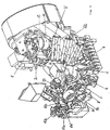
- eine perspektivische Darstellung eines Applizierkopfes einer Vorrichtung zum Applizieren eines elastoplastischen Abstandhalterbandes
- Fig. 2
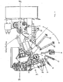
- den gleichen Applizierkopf, gesehen etwa aus der Richtung "A" in Fig. 1
- Fig. 3
- eine der Fig. 2 entsprechende, etwas vereinfachte Aufsicht und
- Fig. 4
- eine Schrägaufsicht mit Band.
- Fig. 1
- a perspective view of an Applizierkopfes a device for applying an elastoplastic spacer strip
- Fig. 2
- the same Applizierkopf, as seen from the direction "A" in Fig. 1
- Fig. 3
- one of FIG. 2 corresponding, somewhat simplified supervision and
- Fig. 4
- an oblique supervision with tape.
Die Vorrichtung zum maschinellen Applizieren eines elastoplastischen Abstandhalterbandes auf eine Glasscheibe entsprechend dem hier vorgeschlagenen Verfahren umfasst eine etwas gegen die Lotrechte geneigte Stützwand für die Gasscheibe, mehrere getrennt steuerbare Horizontalförderer im Bereich des Unterrandes der Stützwand, im Abstand von der Stützwand eine zu dieser parallele Säule und einen an der Säule aufwärts und abwärts verfahrbaren Schlitten, der einen Applizierkopf trägt. Alle vorgenannten Teile sind an sich bekannt,' ebenso deren Bewegungsabläufe. Mit Vorrichtungen dieser Gattung werden unter anderem die Randfugen zwischen eine Isolierglaseinheit bildenden Glasscheiben mit Versiegelungsmasse verfüllt oder plastische Abstandhalter aufgebracht. In der Zeichnung ist deshalb lediglich der besondere Applizierkopf zum Applizieren eines elastoplastischen Abstandhalterbandes dargestellt.The device for the mechanical application of an elastoplastic spacer strip on a glass according to the method proposed here comprises a slightly inclined against the perpendicular support wall for the gas disk, a plurality of separately controllable horizontal conveyor in the lower edge of the support wall, at a distance from the support wall a parallel to this column and a slide movable up and down the column supporting an applicator head. All the above parts are known per se, 'as their movements. With devices of this type, inter alia, the edge joints between an insulating glass unit forming glass sheets are filled with sealant or applied plastic spacers. In the drawing, therefore, only the special Applizierkopf for applying an elastoplastic spacer tape is shown.
Der Applizierkopf, der zum Abfahren der in der Regel vier Seitenränder einer Glasscheibe in an sich bekannter Weise um die Achse B-B in Fig. 3 schrittweise wendbar ist, umfasst, in Richtung des Bandtransportes von einer nicht dargestellten Vorratstrommel zur Applizierstelle, folgende, im vorliegenden Zusammenhang funktionswesentlichen Teile:
- Eine erster Bandtransport 1 wird über eine Maschinensteuerung 50 und zwei Zahnriemen 2, 2' (vergl. Fig. 2) regelbar angetrieben und umfasst vier
Rollen sowie 12 und 14 zusammenwirken und optimal für Bänder unterschiedlicher Breite bestimmt sind. Dem Bandtransport 1 wird das Band stehend oder hochkant von der nicht dargestellten Vorratstrommel spannungsfrei zugeführt. Hierzu ist die Vorratstrommel mit einem über die Maschinensteuerung geregelten Abwickelantrieb versehen. - An den Bandtransport 1 schließt sich eine im Bogen geführte Ausgleichstrecke 3 (vgl. Fig. 3) an, in der das Band zwischen schlitzförmigen Führungen, bestehend aus drei Führungs-
und Stützrollenpaaren - Die Ausgleichstrecke (3) endet an einer sechs
Rollen umfassenden Bandführung 4, auf welche drei Rollenpaare 5, 6 und 7 folgen, die das Band um 90° in eine "liegende" Orientierung wenden.Weitere Rollen 8 übernehmen die Seitenführung. - Dann läuft das Band in einen zweiten Bandtransport 9 ein, der zwei zusammenwirkende
Rollen 91und 92 umfasst, die über einen Zahnriemen 93 von der Maschinensteuerung regelbar angetrieben werden. - Der zweite Bandtransport 9 führt das Band der eigentlichen Applizierstelle zu. Diese umfasst neben den üblichen Andruckrollen 10a (für die horizontalen Schenkel des späteren Rahmens) und 10b (für die vertikalen Schenkel des späteren Rahmens) die ebenfalls üblichen und deshalb nicht näher erläuterten Einrichtungen zum Ausstanzen der Gehrungskeile an den Stellen, an denen der Applizierkopf zur Ausbildung einer Ecke gewendet wird sowie einen
Hebel 10c mit einer Bandauflage 10d (vgl. Fig. 2).Der Hebel 10c ist schwenkbar und unterstützt im Wiederausfall das Band, insbesondere bei Annäherung an eine zu bildende Ecke und/oder vor, während und nach dem Abschneiden des Bandes am Ende des Abfahrens der Kontur der Glasscheibe zur Erzeugung eines geschlossenen Abstandhalterrahmens. - In der Ausgleichstrecke 3, nämlich an den Schmalseiten des durch
das Rollenpaar 32 begrenzten,Führungsschlitzes, sind an der Bogeninnenseite ein ersterSensor 21 und an der Bogenaußenseiteein zweiter Sensor 22 angeordnet.Die Sensoren dem Sensor 21, dann erhöht auf dessen Signal die Maschinensteuerung geringfügig die Antriebsdrehzahl und damit die Umfangsgeschwindigkeit des entsprechenden Rollenpaares 11, 13 (oder 12, 14) des Bandtransportes 1 und verhindert damit, dass auf das Band eine Zugspannung ausgeübt wird. Nähert sich umgekehrt das Band infolge einer Überlieferung durch den Bandtransport 1dem bogenaußenseitigen Sensor 22, so gibt dieser das entsprechende Signal an die Maschinensteuerung, die daraufhin die Umfangsgeschwindigkeit des entsprechenden Rollenpaares des Bandtransportes 1 geringfügig verringert und dadurch verhindert, dass das Band vor dem Bandtransport 9 gestaucht und in diesem Zustand appliziert wird.
- A first belt transport 1 is controllably driven via a
machine control 50 and twotoothed belts 2, 2 '(see FIG. 2) and comprises fourrollers - The belt transport 1 is followed by an arcuate compensating section 3 (see Fig. 3), in which the strip is guided between slot-shaped guides, consisting of three guide and support roller pairs 31, 32, 33, so that it is transverse to its transport direction in the side plane, but not in the height level, can dodge.
- The equalizing section (3) terminates at a six-
roll tape guide 4, followed by three pairs ofrollers Other rollers 8 take over the side guide. - Then, the belt enters a second belt transport 9, which comprises two cooperating
rollers toothed belt 93. - The second belt transport 9 leads the belt to the actual application point. This includes besides the conventional pinch rollers 10a (for the horizontal leg of the later frame) and 10b (for the vertical leg of the later frame) also common and therefore not further explained means for punching the miter wedges at the points where the Applizierkopf is turned to form a corner and a
lever 10c with a band support 10d (see Fig. 2). Thelever 10c is pivotable and, in the event of re-occurrence, assists the belt, in particular when approaching a corner to be formed and / or before, during and after cutting off the belt at the end of the travel of the contour of the glass pane to produce a closed spacer frame. - In the compensating section 3, namely on the narrow sides of the guide slot bounded by the pair of
rollers 32, afirst sensor 21 is arranged on the inside of the arch and asecond sensor 22 is arranged on the outside of the arch. Thesensors sensor 21 as a result of being underdelivered by the tape transport 1 in relation to the peripheral speed of the tape transport 9 determined by the instantaneous application speed, then the machine controller slightly increases the drive speed and thus the peripheral speed of the corresponding pair ofrollers 11, 13 (or 12, 14) of the tape transport 1 and thus prevents the tape from being subjected to tensile stress. Conversely, when the tape approaches the outside of the sheet-fedsensor 22 as a result of transmission by the tape transport 1, it gives the corresponding signal to the machine control, which then sets the peripheral speed of the corresponding roller pair of the tape transport 1 slightly reduced and thereby prevents the belt is compressed before the tape transport 9 and applied in this state.
Claims (11)
- A method for mechanically applying an elastoplastic spacer band onto a glass pane which is determined for assembly with at least one further glass pane for an insulating glass unit, comprising the following steps:- unrolling the band in a manner free from tensile stress from a delivery drum with a linear speed corresponding to at least on average the application speed;- supplying of the band to the application point in a manner free from tensile stress and shearing stress.
- A method according to claim 1, characterized in that- the band is supplied by means of a first driven pair of rollers (1) of a compensating section (3) for the delivery to the application point in a manner free from tensile stress and shearing stress and is supplied at its end by means of a second driven pair of rollers (9) to the application point;- the circumferential speed of the second pair of rollers (9) is regulated in a synchronous manner relative to the application speed, and- the band length in the compensating section (3) between the first and the second pair of rollers (1, 9) is determined and the circumferential speed of the first pair of rollers (1) is regulated depending on the same.
- A method according to claim 2, characterized in that the band length in the compensating section (3) is determined by means of at least one sensor (21, 22) responding to the position of the band.
- A method according to claim 3, characterized in that the circumferential speed of the first pair of rollers (1) is increased or decreased depending on the position of the band in the compensating section (3) as determined by means of the at least one sensor, so that the band remains free of tension in the compensating section (3) at least close to a predetermined specified position.
- A method according to one of the claims 2 to 4, characterized in that the band in the compensating section (3) is supported in a manner at least free from sagging.
- A method according to one of the claims 2 to 5, characterized in that the band in the compensating section (3) is guided and supported in a bend with a radius depending on the difference of the circumferential speeds of the first and second pair of rollers (1, 9).
- A method according to one of the claims 1 to 6, characterized in that the band is supplied by means of an application head which can be turned about an axis orthogonal relative to the plane of the glass pane and the first pair of rollers (1) and all subsequent band conveyance and guiding devices are arranged on the same.
- An apparatus for the mechanical application of an elastoplastic spacer band onto a glass pane and especially for performing the method according to one of the claims 1 to 7, comprising- a supporting wall for the glass pane which is inclined slightly against the perpendicular;- at least one horizontal conveyor in the region of the lower edge of the supporting wall;- a pillar in a plane parallel to the plane of the supporting wall;- an application head which is movable on the pillar between the lower edge and the upper edge of the supporting wall and which can be turned in steps about an axis orthogonal relative to the plane of the supporting wall;- devices for feeding the band from a delivery drum and for pressing and cutting the band accurate to size;- a machine control unit for measuring, controlling and monitoring the movements of the parts of the apparatus and the transport of the band;characterized in that- the devices for supplying the band comprise at least one first pair of rollers (1) with a drive controllable via the machine control unit, a compensating section (3) with supporting rollers (31, 32, 33) for the band, a second pair of rollers (9) with a drive controllable via the machine control unit, and at least one sensor (21, 22) for recognizing the position of the band in the compensating section (3), so that the supply of the band to the application point occurs in a manner free from tensile stress and shearing stress.
- An apparatus according to claim 8, characterized in that the delivery drum has an unwinding drive which can be controlled synchronously to the application speed via the machine control unit.
- An apparatus according to claim 8 or 9, characterized in that the compensating section (3) between the first and the second pair of rollers comprises at least one slot-like guide means (31, 32, 33) for the band, with the long axis of the guide slot extending substantially orthogonally to the band conveying direction, and the slot width is only slightly larger than the width of the band.
- An apparatus according to one of the claims 8 to 10, characterized in that a swivelable lever (10c) is arranged at the application point, which lever supports the band close to the application point especially during the turning of the application head.
Applications Claiming Priority (2)
| Application Number | Priority Date | Filing Date | Title |
|---|---|---|---|
| DE10212359A DE10212359B4 (en) | 2002-03-20 | 2002-03-20 | Method and device for machine application of a spacer strip on a glass pane |
| DE10212359 | 2002-03-20 |
Publications (4)
| Publication Number | Publication Date |
|---|---|
| EP1347142A2 EP1347142A2 (en) | 2003-09-24 |
| EP1347142A3 EP1347142A3 (en) | 2004-07-28 |
| EP1347142B1 true EP1347142B1 (en) | 2006-05-03 |
| EP1347142B2 EP1347142B2 (en) | 2011-10-19 |
Family
ID=27771449
Family Applications (1)
| Application Number | Title | Priority Date | Filing Date |
|---|---|---|---|
| EP03003854A Expired - Lifetime EP1347142B2 (en) | 2002-03-20 | 2003-02-20 | Process and device for mechanically applying a spacer ribbon onto a glass pane |
Country Status (6)
| Country | Link |
|---|---|
| US (2) | US7008492B2 (en) |
| EP (1) | EP1347142B2 (en) |
| CN (1) | CN1239805C (en) |
| AT (1) | ATE325252T1 (en) |
| DE (2) | DE10212359B4 (en) |
| ES (1) | ES2262912T5 (en) |
Cited By (1)
| Publication number | Priority date | Publication date | Assignee | Title |
|---|---|---|---|---|
| EP2549048A1 (en) | 2011-07-19 | 2013-01-23 | For.El. S.P.A. | Automatic machine and method for alternable application of a plurality of flexible spacer profiles on a glass sheet |
Families Citing this family (29)
| Publication number | Priority date | Publication date | Assignee | Title |
|---|---|---|---|---|
| US20030038528A1 (en) * | 2000-08-22 | 2003-02-27 | Youngi Kim | Pocket wheel cover for portable golf cart |
| DE10350312B4 (en) * | 2003-10-28 | 2005-12-01 | Peter Lisec | Method and device for applying an elastoplastic tape in the manufacture of an insulating glass pane |
| KR101092316B1 (en) * | 2004-02-04 | 2011-12-09 | 에지테크 아이지 인코포레이티드 | A method for forming an insulating glazing unit |
| DE102004009858B4 (en) * | 2004-02-25 | 2006-05-04 | Karl Lenhardt | Method for positioning glass sheets in a vertical assembly and pressing device for insulating glass panes |
| DE102004032023B4 (en) * | 2004-07-01 | 2007-06-06 | Peter Lisec | Method and device for producing an insulating glass pane |
| CN101043973B (en) * | 2004-08-20 | 2010-05-05 | 亨特道格拉斯有限公司 | Apparatus and method for making a window covering having operable vanes |
| ITTV20040117A1 (en) | 2004-10-20 | 2005-01-20 | For El Base Di Vianello Fortun | AUTOMATIC MACHINE FOR THE APPLICATION OF SPACER PROFILE ON GLASS SHEET AND AUTOMATIC PROCEDURE FOR THE APPLICATION OF SPACER PROFILE ON GLASS SHEET. |
| DE102005058028B3 (en) * | 2005-12-05 | 2007-08-02 | Peter Lisec | Method and device for closing the corner joint of the spacer of an insulating glass pane |
| US9309714B2 (en) | 2007-11-13 | 2016-04-12 | Guardian Ig, Llc | Rotating spacer applicator for window assembly |
| US8967219B2 (en) | 2010-06-10 | 2015-03-03 | Guardian Ig, Llc | Window spacer applicator |
| EP2220321A1 (en) | 2007-11-13 | 2010-08-25 | Infinite Edge Technologies, LLC | Reinforced window spacer |
| IT1391489B1 (en) * | 2008-10-17 | 2011-12-23 | For El S P A | AUTOMATIC MACHINE FOR THE CONTINUOUS EXTRUSION OF THERMOPLASTIC SEALANT ON THE SPACER PROFILE DURING THE DISCONTINUOUS APPLICATION OF THE SAME ON GLASS SHEET AND AUTOMATIC PROCEDURE FOR THE CONTINUOUS EXTRUSION OF THERMOPLASTIC SEALANT ON THE SPACER PROFILE DURING THE DISCONTINUOUS APPLICATION OF THE SAME ON GLASS SHEET. |
| US8586193B2 (en) * | 2009-07-14 | 2013-11-19 | Infinite Edge Technologies, Llc | Stretched strips for spacer and sealed unit |
| AT508998B1 (en) | 2009-10-22 | 2011-07-15 | Inova Lisec Technologiezentrum | APPARATUS FOR APPLYING FLEXIBLE SPACER BELTS |
| AT11889U1 (en) | 2009-10-22 | 2011-06-15 | Inova Lisec Technologiezentrum | DEVICE FOR APPLYING DISTANCE HOLDERS ON GLASS PANES |
| AT509993B1 (en) | 2010-09-23 | 2012-01-15 | Inova Lisec Technologiezentrum | PLASTER BETWEEN THE END OF PRE-PREPARED SPACERS FOR INSULATING GLASS AND METHOD FOR MANUFACTURING THE SAME |
| US9228389B2 (en) | 2010-12-17 | 2016-01-05 | Guardian Ig, Llc | Triple pane window spacer, window assembly and methods for manufacturing same |
| US9260907B2 (en) | 2012-10-22 | 2016-02-16 | Guardian Ig, Llc | Triple pane window spacer having a sunken intermediate pane |
| US9689196B2 (en) | 2012-10-22 | 2017-06-27 | Guardian Ig, Llc | Assembly equipment line and method for windows |
| AT513390B1 (en) * | 2012-10-22 | 2014-04-15 | Lisec Austria Gmbh | Method and device for automated replacement of spacers |
| US9656356B2 (en) | 2013-01-22 | 2017-05-23 | Guardian Ig, Llc | Window unit assembly station and method |
| US9951553B2 (en) | 2014-06-05 | 2018-04-24 | Erdman Automation Corporation | High speed parallel process insulated glass manufacturing line |
| DE102015113865A1 (en) * | 2014-09-24 | 2016-03-24 | Bystronic Lenhardt Gmbh | Method and apparatus for feeding a film in the manufacture of laminated safety glass |
| DE102014115218B3 (en) * | 2014-10-20 | 2016-04-14 | Bystronic Lenhardt Gmbh | Method for forming a closed frame-shaped spacer for an insulating glass pane |
| US10253552B2 (en) | 2016-04-21 | 2019-04-09 | Erdman Automation Corporation | High speed parallel process insulated glass manufacturing line |
| CN106864155B (en) * | 2017-04-24 | 2019-07-05 | 无锡兢腾建筑装饰工程有限公司 | A kind of device pasted for wallpaper |
| US11352831B2 (en) | 2019-05-24 | 2022-06-07 | PDS IG Holding LLC | Glass seal tracking spacer applicator |
| DE102022118884A1 (en) | 2022-07-27 | 2024-02-01 | Glaston Germany GmbH | Insulating glass pane with rung insert and manufacturing process, rung insert, rung holder and spacer tape for such |
| CN117087924B (en) * | 2023-10-17 | 2023-12-29 | 福建傲顿科技有限公司 | Transfer equipment for electric heating film glass plate |
Family Cites Families (7)
| Publication number | Priority date | Publication date | Assignee | Title |
|---|---|---|---|---|
| CA1126581A (en) * | 1979-01-29 | 1982-06-29 | Thomas W. Greenlee | Dimensionally stable sealant and spacer strip and composite structures comprising the same |
| DE3404006A1 (en) † | 1984-02-06 | 1985-08-08 | Karl 7531 Neuhausen Lenhardt | DEVICE FOR APPLYING AN ADHESIVE STRING OF PLASTIC TO A GLASS PANEL |
| US4888341A (en) * | 1984-09-04 | 1989-12-19 | University Patents, Inc. | 6-substituted mitomycin analogs |
| AT390433B (en) * | 1986-09-01 | 1990-05-10 | Lisec Peter | DEVICE FOR APPLYING FLEXIBLE SPACERS |
| US5888341A (en) † | 1994-05-26 | 1999-03-30 | Lafond; Luc | Apparatus for the automated application of spacer material |
| WO1998022687A1 (en) * | 1995-05-25 | 1998-05-28 | Luc Lafond | Apparatus for the automated application of spacer material and method of using same |
| US5779830A (en) * | 1995-10-24 | 1998-07-14 | Truseal Technologies, Inc. | Flexible tape applicator and method of operation |
-
2002
- 2002-03-20 DE DE10212359A patent/DE10212359B4/en not_active Withdrawn - After Issue
-
2003
- 2003-02-20 EP EP03003854A patent/EP1347142B2/en not_active Expired - Lifetime
- 2003-02-20 AT AT03003854T patent/ATE325252T1/en active
- 2003-02-20 DE DE50303153T patent/DE50303153D1/en not_active Expired - Lifetime
- 2003-02-20 ES ES03003854T patent/ES2262912T5/en not_active Expired - Lifetime
- 2003-03-18 CN CN03119398.6A patent/CN1239805C/en not_active Expired - Lifetime
- 2003-03-19 US US10/390,754 patent/US7008492B2/en not_active Expired - Lifetime
-
2005
- 2005-11-23 US US11/285,174 patent/US7523776B2/en not_active Expired - Lifetime
Cited By (1)
| Publication number | Priority date | Publication date | Assignee | Title |
|---|---|---|---|---|
| EP2549048A1 (en) | 2011-07-19 | 2013-01-23 | For.El. S.P.A. | Automatic machine and method for alternable application of a plurality of flexible spacer profiles on a glass sheet |
Also Published As
| Publication number | Publication date |
|---|---|
| DE50303153D1 (en) | 2006-06-08 |
| US7008492B2 (en) | 2006-03-07 |
| CN1445429A (en) | 2003-10-01 |
| CN1239805C (en) | 2006-02-01 |
| US20060076110A1 (en) | 2006-04-13 |
| DE10212359A1 (en) | 2003-10-09 |
| DE10212359B4 (en) | 2005-10-06 |
| ATE325252T1 (en) | 2006-06-15 |
| EP1347142A2 (en) | 2003-09-24 |
| ES2262912T3 (en) | 2006-12-01 |
| US20030178127A1 (en) | 2003-09-25 |
| EP1347142B2 (en) | 2011-10-19 |
| ES2262912T5 (en) | 2012-03-07 |
| US7523776B2 (en) | 2009-04-28 |
| EP1347142A3 (en) | 2004-07-28 |
Similar Documents
| Publication | Publication Date | Title |
|---|---|---|
| EP1347142B1 (en) | Process and device for mechanically applying a spacer ribbon onto a glass pane | |
| EP1646762B1 (en) | Method and device for producing an insulating glass plane | |
| DE2156406A1 (en) | Method and device for marking or cutting strip materials | |
| DE2905841A1 (en) | METHOD AND DEVICE FOR THE PRODUCTION OF COMPOSITE PANELS, IN PARTICULAR COMPOSED GLASS PANELS | |
| DE1906939C3 (en) | Device for butt joining two thin webs of material following one another in the direction of travel | |
| DE10350312B4 (en) | Method and device for applying an elastoplastic tape in the manufacture of an insulating glass pane | |
| DE3039293A1 (en) | DEVICE FOR FEEDING A WRAPPING SHEET TO A LARGE PAPER ROLL OR THE LIKE. | |
| EP0324333B1 (en) | Device for filling insulating glass with special gas | |
| EP2408991B1 (en) | Device for applying spacer tape | |
| DE112006001777T5 (en) | sheet sticking | |
| EP2404018B1 (en) | Device and method for applying spacer tapes to glass panes | |
| EP0173045A1 (en) | Flatness control in strip rolling stands | |
| DE2157567A1 (en) | Block formed by a stack of sheets of glass, and the method and apparatus for making it | |
| DE102018206468B4 (en) | Tape offset dispenser | |
| DE102019006046A1 (en) | Device and method for intermittent conveying of a web of material along a conveying direction and for cutting the web of material | |
| EP3000597A1 (en) | Method and device for feeding a foil in the production of laminated safety glass | |
| DE2748551C3 (en) | Device for removing films from a cassette | |
| DE60007752T2 (en) | APPARATUS AND METHOD FOR REWINDING RAILS | |
| DE102009022248B4 (en) | Entwölbungsvorrichtung for Entwölbung a web, especially in a plant of the paper processing industry | |
| DE3001520C2 (en) | Device for cutting split tiles from a strand of clay | |
| DE2625457C3 (en) | Recorder | |
| DE2248569A1 (en) | GLUING MACHINE WITH SINGLE ROD | |
| DE3220587C2 (en) | Method and device for cutting and winding up small tapes, in particular made of adhesive-coated foils | |
| DE1752777C (en) | Unwinding and straightening station of a device for the production of welded screw seam tubes from metal strip | |
| EP0102448A1 (en) | Apparatus for the insertion of an elastic sealing strip into a joint of a structure |
Legal Events
| Date | Code | Title | Description |
|---|---|---|---|
| PUAI | Public reference made under article 153(3) epc to a published international application that has entered the european phase |
Free format text: ORIGINAL CODE: 0009012 |
|
| AK | Designated contracting states |
Kind code of ref document: A2 Designated state(s): AT BE BG CH CY CZ DE DK EE ES FI FR GB GR HU IE IT LI LU MC NL PT SE SI SK TR |
|
| AX | Request for extension of the european patent |
Extension state: AL LT LV MK RO |
|
| PUAL | Search report despatched |
Free format text: ORIGINAL CODE: 0009013 |
|
| AK | Designated contracting states |
Kind code of ref document: A3 Designated state(s): AT BE BG CH CY CZ DE DK EE ES FI FR GB GR HU IE IT LI LU MC NL PT SE SI SK TR |
|
| AX | Request for extension of the european patent |
Extension state: AL LT LV MK RO |
|
| RIC1 | Information provided on ipc code assigned before grant |
Ipc: 7E 06B 3/673 A |
|
| 17P | Request for examination filed |
Effective date: 20040715 |
|
| AKX | Designation fees paid |
Designated state(s): AT BE BG CH CY CZ DE DK EE ES FI FR GB GR HU IE IT LI LU MC NL PT SE SI SK TR |
|
| GRAP | Despatch of communication of intention to grant a patent |
Free format text: ORIGINAL CODE: EPIDOSNIGR1 |
|
| GRAS | Grant fee paid |
Free format text: ORIGINAL CODE: EPIDOSNIGR3 |
|
| GRAA | (expected) grant |
Free format text: ORIGINAL CODE: 0009210 |
|
| AK | Designated contracting states |
Kind code of ref document: B1 Designated state(s): AT BE BG CH CY CZ DE DK EE ES FI FR GB GR HU IE IT LI LU MC NL PT SE SI SK TR |
|
| PG25 | Lapsed in a contracting state [announced via postgrant information from national office to epo] |
Ref country code: IT Free format text: LAPSE BECAUSE OF FAILURE TO SUBMIT A TRANSLATION OF THE DESCRIPTION OR TO PAY THE FEE WITHIN THE PRESCRIBED TIME-LIMIT;WARNING: LAPSES OF ITALIAN PATENTS WITH EFFECTIVE DATE BEFORE 2007 MAY HAVE OCCURRED AT ANY TIME BEFORE 2007. THE CORRECT EFFECTIVE DATE MAY BE DIFFERENT FROM THE ONE RECORDED. Effective date: 20060503 Ref country code: FI Free format text: LAPSE BECAUSE OF FAILURE TO SUBMIT A TRANSLATION OF THE DESCRIPTION OR TO PAY THE FEE WITHIN THE PRESCRIBED TIME-LIMIT Effective date: 20060503 Ref country code: IE Free format text: LAPSE BECAUSE OF FAILURE TO SUBMIT A TRANSLATION OF THE DESCRIPTION OR TO PAY THE FEE WITHIN THE PRESCRIBED TIME-LIMIT Effective date: 20060503 Ref country code: SI Free format text: LAPSE BECAUSE OF FAILURE TO SUBMIT A TRANSLATION OF THE DESCRIPTION OR TO PAY THE FEE WITHIN THE PRESCRIBED TIME-LIMIT Effective date: 20060503 Ref country code: NL Free format text: LAPSE BECAUSE OF FAILURE TO SUBMIT A TRANSLATION OF THE DESCRIPTION OR TO PAY THE FEE WITHIN THE PRESCRIBED TIME-LIMIT Effective date: 20060503 Ref country code: CZ Free format text: LAPSE BECAUSE OF FAILURE TO SUBMIT A TRANSLATION OF THE DESCRIPTION OR TO PAY THE FEE WITHIN THE PRESCRIBED TIME-LIMIT Effective date: 20060503 Ref country code: SK Free format text: LAPSE BECAUSE OF FAILURE TO SUBMIT A TRANSLATION OF THE DESCRIPTION OR TO PAY THE FEE WITHIN THE PRESCRIBED TIME-LIMIT Effective date: 20060503 |
|
| REG | Reference to a national code |
Ref country code: GB Ref legal event code: FG4D Free format text: NOT ENGLISH |
|
| REG | Reference to a national code |
Ref country code: CH Ref legal event code: EP Ref country code: CH Ref legal event code: NV Representative=s name: LUCHS & PARTNER PATENTANWAELTE |
|
| GBT | Gb: translation of ep patent filed (gb section 77(6)(a)/1977) |
Effective date: 20060504 |
|
| REF | Corresponds to: |
Ref document number: 50303153 Country of ref document: DE Date of ref document: 20060608 Kind code of ref document: P |
|
| REG | Reference to a national code |
Ref country code: IE Ref legal event code: FG4D Free format text: LANGUAGE OF EP DOCUMENT: GERMAN |
|
| PG25 | Lapsed in a contracting state [announced via postgrant information from national office to epo] |
Ref country code: SE Free format text: LAPSE BECAUSE OF FAILURE TO SUBMIT A TRANSLATION OF THE DESCRIPTION OR TO PAY THE FEE WITHIN THE PRESCRIBED TIME-LIMIT Effective date: 20060803 Ref country code: DK Free format text: LAPSE BECAUSE OF FAILURE TO SUBMIT A TRANSLATION OF THE DESCRIPTION OR TO PAY THE FEE WITHIN THE PRESCRIBED TIME-LIMIT Effective date: 20060803 |
|
| PG25 | Lapsed in a contracting state [announced via postgrant information from national office to epo] |
Ref country code: PT Free format text: LAPSE BECAUSE OF FAILURE TO SUBMIT A TRANSLATION OF THE DESCRIPTION OR TO PAY THE FEE WITHIN THE PRESCRIBED TIME-LIMIT Effective date: 20061003 |
|
| NLV1 | Nl: lapsed or annulled due to failure to fulfill the requirements of art. 29p and 29m of the patents act | ||
| REG | Reference to a national code |
Ref country code: ES Ref legal event code: FG2A Ref document number: 2262912 Country of ref document: ES Kind code of ref document: T3 |
|
| ET | Fr: translation filed | ||
| REG | Reference to a national code |
Ref country code: IE Ref legal event code: FD4D |
|
| PLBI | Opposition filed |
Free format text: ORIGINAL CODE: 0009260 |
|
| PG25 | Lapsed in a contracting state [announced via postgrant information from national office to epo] |
Ref country code: MC Free format text: LAPSE BECAUSE OF NON-PAYMENT OF DUE FEES Effective date: 20070228 |
|
| PLAX | Notice of opposition and request to file observation + time limit sent |
Free format text: ORIGINAL CODE: EPIDOSNOBS2 |
|
| 26 | Opposition filed |
Opponent name: LENHARDT MASCHINENBAU GMBH Effective date: 20070118 |
|
| PLBB | Reply of patent proprietor to notice(s) of opposition received |
Free format text: ORIGINAL CODE: EPIDOSNOBS3 |
|
| BERE | Be: lapsed |
Owner name: LISEC, PETER Effective date: 20070228 |
|
| PG25 | Lapsed in a contracting state [announced via postgrant information from national office to epo] |
Ref country code: BE Free format text: LAPSE BECAUSE OF NON-PAYMENT OF DUE FEES Effective date: 20070228 |
|
| PG25 | Lapsed in a contracting state [announced via postgrant information from national office to epo] |
Ref country code: GR Free format text: LAPSE BECAUSE OF FAILURE TO SUBMIT A TRANSLATION OF THE DESCRIPTION OR TO PAY THE FEE WITHIN THE PRESCRIBED TIME-LIMIT Effective date: 20060804 |
|
| PG25 | Lapsed in a contracting state [announced via postgrant information from national office to epo] |
Ref country code: BG Free format text: LAPSE BECAUSE OF FAILURE TO SUBMIT A TRANSLATION OF THE DESCRIPTION OR TO PAY THE FEE WITHIN THE PRESCRIBED TIME-LIMIT Effective date: 20060803 |
|
| PG25 | Lapsed in a contracting state [announced via postgrant information from national office to epo] |
Ref country code: EE Free format text: LAPSE BECAUSE OF FAILURE TO SUBMIT A TRANSLATION OF THE DESCRIPTION OR TO PAY THE FEE WITHIN THE PRESCRIBED TIME-LIMIT Effective date: 20060503 |
|
| PGRI | Patent reinstated in contracting state [announced from national office to epo] |
Ref country code: IT Effective date: 20081001 |
|
| REG | Reference to a national code |
Ref country code: CH Ref legal event code: PUE Owner name: TECNOPAT AG Free format text: LISEC, PETER#BAHNHOFSTRASSE 34#A-3363 AMSTETTEN-HAUSMENING (AT) -TRANSFER TO- TECNOPAT AG#ST. LEONHARD-STRASSE 65#9000 ST. GALLEN (CH) |
|
| APAH | Appeal reference modified |
Free format text: ORIGINAL CODE: EPIDOSCREFNO |
|
| APBM | Appeal reference recorded |
Free format text: ORIGINAL CODE: EPIDOSNREFNO |
|
| APBP | Date of receipt of notice of appeal recorded |
Free format text: ORIGINAL CODE: EPIDOSNNOA2O |
|
| REG | Reference to a national code |
Ref country code: GB Ref legal event code: 732E |
|
| RAP2 | Party data changed (patent owner data changed or rights of a patent transferred) |
Owner name: TECNOPAT AG |
|
| RIN2 | Information on inventor provided after grant (corrected) |
Inventor name: TECNOPAT AG |
|
| REG | Reference to a national code |
Ref country code: CH Ref legal event code: NV Representative=s name: LUCHS & PARTNER PATENTANWAELTE |
|
| APBQ | Date of receipt of statement of grounds of appeal recorded |
Free format text: ORIGINAL CODE: EPIDOSNNOA3O |
|
| PG25 | Lapsed in a contracting state [announced via postgrant information from national office to epo] |
Ref country code: CY Free format text: LAPSE BECAUSE OF FAILURE TO SUBMIT A TRANSLATION OF THE DESCRIPTION OR TO PAY THE FEE WITHIN THE PRESCRIBED TIME-LIMIT Effective date: 20060503 Ref country code: LU Free format text: LAPSE BECAUSE OF NON-PAYMENT OF DUE FEES Effective date: 20070220 |
|
| PGRI | Patent reinstated in contracting state [announced from national office to epo] |
Ref country code: IT Effective date: 20081001 |
|
| REG | Reference to a national code |
Ref country code: FR Ref legal event code: TP |
|
| PG25 | Lapsed in a contracting state [announced via postgrant information from national office to epo] |
Ref country code: HU Free format text: LAPSE BECAUSE OF FAILURE TO SUBMIT A TRANSLATION OF THE DESCRIPTION OR TO PAY THE FEE WITHIN THE PRESCRIBED TIME-LIMIT Effective date: 20061104 Ref country code: TR Free format text: LAPSE BECAUSE OF FAILURE TO SUBMIT A TRANSLATION OF THE DESCRIPTION OR TO PAY THE FEE WITHIN THE PRESCRIBED TIME-LIMIT Effective date: 20060503 |
|
| APBU | Appeal procedure closed |
Free format text: ORIGINAL CODE: EPIDOSNNOA9O |
|
| PUAH | Patent maintained in amended form |
Free format text: ORIGINAL CODE: 0009272 |
|
| STAA | Information on the status of an ep patent application or granted ep patent |
Free format text: STATUS: PATENT MAINTAINED AS AMENDED |
|
| 27A | Patent maintained in amended form |
Effective date: 20111019 |
|
| AK | Designated contracting states |
Kind code of ref document: B2 Designated state(s): AT BE BG CH CY CZ DE DK EE ES FI FR GB GR HU IE IT LI LU MC NL PT SE SI SK TR |
|
| REG | Reference to a national code |
Ref country code: DE Ref legal event code: R102 Ref document number: 50303153 Country of ref document: DE |
|
| REG | Reference to a national code |
Ref country code: CH Ref legal event code: AEN Free format text: AUFRECHTERHALTUNG DES PATENTES IN GEAENDERTER FORM |
|
| REG | Reference to a national code |
Ref country code: DE Ref legal event code: R102 Ref document number: 50303153 Country of ref document: DE Effective date: 20111019 |
|
| REG | Reference to a national code |
Ref country code: ES Ref legal event code: DC2A Ref document number: 2262912 Country of ref document: ES Kind code of ref document: T5 Effective date: 20120307 |
|
| REG | Reference to a national code |
Ref country code: DE Ref legal event code: R082 Ref document number: 50303153 Country of ref document: DE Representative=s name: PATENTANWAELTE HENKEL, BREUER & PARTNER, DE Ref country code: DE Ref legal event code: R082 Ref document number: 50303153 Country of ref document: DE Representative=s name: PATENTANWAELTE HENKEL, BREUER & PARTNER MBB, DE |
|
| REG | Reference to a national code |
Ref country code: FR Ref legal event code: PLFP Year of fee payment: 14 |
|
| REG | Reference to a national code |
Ref country code: FR Ref legal event code: PLFP Year of fee payment: 15 |
|
| REG | Reference to a national code |
Ref country code: FR Ref legal event code: PLFP Year of fee payment: 16 |
|
| REG | Reference to a national code |
Ref country code: AT Ref legal event code: HC Ref document number: 325252 Country of ref document: AT Kind code of ref document: T Owner name: LISEC TECNOPAT GMBH, AT Effective date: 20200212 |
|
| REG | Reference to a national code |
Ref country code: DE Ref legal event code: R082 Ref document number: 50303153 Country of ref document: DE Representative=s name: HENKEL & PARTNER MBB PATENTANWALTSKANZLEI, REC, DE Ref country code: DE Ref legal event code: R081 Ref document number: 50303153 Country of ref document: DE Owner name: LISEC TECNOPAT GMBH, AT Free format text: FORMER OWNER: TECNOPAT AG, ST. GALLEN, CH |
|
| REG | Reference to a national code |
Ref country code: CH Ref legal event code: PFA Owner name: LISEC TECNOPAT GMBH, AT Free format text: FORMER OWNER: TECNOPAT AG, CH |
|
| REG | Reference to a national code |
Ref country code: ES Ref legal event code: PC2A Owner name: LISEC TECNOPAT GMBH Effective date: 20201123 |
|
| PGFP | Annual fee paid to national office [announced via postgrant information from national office to epo] |
Ref country code: GB Payment date: 20220221 Year of fee payment: 20 Ref country code: DE Payment date: 20220208 Year of fee payment: 20 Ref country code: CH Payment date: 20220221 Year of fee payment: 20 Ref country code: AT Payment date: 20220215 Year of fee payment: 20 |
|
| PGFP | Annual fee paid to national office [announced via postgrant information from national office to epo] |
Ref country code: IT Payment date: 20220228 Year of fee payment: 20 Ref country code: FR Payment date: 20220221 Year of fee payment: 20 Ref country code: ES Payment date: 20220318 Year of fee payment: 20 |
|
| REG | Reference to a national code |
Ref country code: DE Ref legal event code: R071 Ref document number: 50303153 Country of ref document: DE |
|
| REG | Reference to a national code |
Ref country code: CH Ref legal event code: PL |
|
| REG | Reference to a national code |
Ref country code: GB Ref legal event code: PE20 Expiry date: 20230219 |
|
| REG | Reference to a national code |
Ref country code: AT Ref legal event code: MK07 Ref document number: 325252 Country of ref document: AT Kind code of ref document: T Effective date: 20230220 |
|
| REG | Reference to a national code |
Ref country code: ES Ref legal event code: FD2A Effective date: 20230426 |
|
| PG25 | Lapsed in a contracting state [announced via postgrant information from national office to epo] |
Ref country code: GB Free format text: LAPSE BECAUSE OF EXPIRATION OF PROTECTION Effective date: 20230219 |
|
| PG25 | Lapsed in a contracting state [announced via postgrant information from national office to epo] |
Ref country code: ES Free format text: LAPSE BECAUSE OF EXPIRATION OF PROTECTION Effective date: 20230221 |