EP1347104A2 - Water discharge valve - Google Patents
Water discharge valve Download PDFInfo
- Publication number
- EP1347104A2 EP1347104A2 EP03003988A EP03003988A EP1347104A2 EP 1347104 A2 EP1347104 A2 EP 1347104A2 EP 03003988 A EP03003988 A EP 03003988A EP 03003988 A EP03003988 A EP 03003988A EP 1347104 A2 EP1347104 A2 EP 1347104A2
- Authority
- EP
- European Patent Office
- Prior art keywords
- valve
- water discharge
- tubular shaft
- discharge valve
- valve housing
- Prior art date
- Legal status (The legal status is an assumption and is not a legal conclusion. Google has not performed a legal analysis and makes no representation as to the accuracy of the status listed.)
- Granted
Links
Images


Classifications
-
- E—FIXED CONSTRUCTIONS
- E03—WATER SUPPLY; SEWERAGE
- E03B—INSTALLATIONS OR METHODS FOR OBTAINING, COLLECTING, OR DISTRIBUTING WATER
- E03B9/00—Methods or installations for drawing-off water
- E03B9/02—Hydrants; Arrangements of valves therein; Keys for hydrants
- E03B9/025—Taps specially designed for outdoor use, e.g. wall hydrants, sill cocks
-
- E—FIXED CONSTRUCTIONS
- E03—WATER SUPPLY; SEWERAGE
- E03B—INSTALLATIONS OR METHODS FOR OBTAINING, COLLECTING, OR DISTRIBUTING WATER
- E03B9/00—Methods or installations for drawing-off water
- E03B9/02—Hydrants; Arrangements of valves therein; Keys for hydrants
- E03B9/14—Draining devices for hydrants
-
- E—FIXED CONSTRUCTIONS
- E03—WATER SUPPLY; SEWERAGE
- E03C—DOMESTIC PLUMBING INSTALLATIONS FOR FRESH WATER OR WASTE WATER; SINKS
- E03C1/00—Domestic plumbing installations for fresh water or waste water; Sinks
- E03C1/02—Plumbing installations for fresh water
- E03C1/10—Devices for preventing contamination of drinking-water pipes, e.g. means for aerating self-closing flushing valves
- E03C1/106—Devices for preventing contamination of drinking-water pipes, e.g. means for aerating self-closing flushing valves using two or more check valves
-
- E—FIXED CONSTRUCTIONS
- E03—WATER SUPPLY; SEWERAGE
- E03C—DOMESTIC PLUMBING INSTALLATIONS FOR FRESH WATER OR WASTE WATER; SINKS
- E03C1/00—Domestic plumbing installations for fresh water or waste water; Sinks
- E03C1/02—Plumbing installations for fresh water
- E03C1/10—Devices for preventing contamination of drinking-water pipes, e.g. means for aerating self-closing flushing valves
- E03C1/108—Devices for preventing contamination of drinking-water pipes, e.g. means for aerating self-closing flushing valves having an aerating valve
-
- F—MECHANICAL ENGINEERING; LIGHTING; HEATING; WEAPONS; BLASTING
- F16—ENGINEERING ELEMENTS AND UNITS; GENERAL MEASURES FOR PRODUCING AND MAINTAINING EFFECTIVE FUNCTIONING OF MACHINES OR INSTALLATIONS; THERMAL INSULATION IN GENERAL
- F16K—VALVES; TAPS; COCKS; ACTUATING-FLOATS; DEVICES FOR VENTING OR AERATING
- F16K24/00—Devices, e.g. valves, for venting or aerating enclosures
- F16K24/02—Devices, e.g. valves, for venting or aerating enclosures the enclosure being itself a valve, tap, or cock
-
- F—MECHANICAL ENGINEERING; LIGHTING; HEATING; WEAPONS; BLASTING
- F16—ENGINEERING ELEMENTS AND UNITS; GENERAL MEASURES FOR PRODUCING AND MAINTAINING EFFECTIVE FUNCTIONING OF MACHINES OR INSTALLATIONS; THERMAL INSULATION IN GENERAL
- F16K—VALVES; TAPS; COCKS; ACTUATING-FLOATS; DEVICES FOR VENTING OR AERATING
- F16K24/00—Devices, e.g. valves, for venting or aerating enclosures
- F16K24/06—Devices, e.g. valves, for venting or aerating enclosures for aerating only
-
- F—MECHANICAL ENGINEERING; LIGHTING; HEATING; WEAPONS; BLASTING
- F16—ENGINEERING ELEMENTS AND UNITS; GENERAL MEASURES FOR PRODUCING AND MAINTAINING EFFECTIVE FUNCTIONING OF MACHINES OR INSTALLATIONS; THERMAL INSULATION IN GENERAL
- F16K—VALVES; TAPS; COCKS; ACTUATING-FLOATS; DEVICES FOR VENTING OR AERATING
- F16K31/00—Actuating devices; Operating means; Releasing devices
- F16K31/44—Mechanical actuating means
- F16K31/46—Mechanical actuating means for remote operation
Definitions
- the present invention relates to a water discharge valve intended to be mounted extending through an external wall element and with control means and outlet located by the outside of the wall.
- the invention relates in particular to a water discharge valve of the above stated type, which facilitates that the water discharge valve is completely drained when closed, even if a hose is connected to the outlet member, and which also prevents a return flow back into the supply pipe of the water discharge valve in case that a pressure drop should occur.
- Water discharge valves of the above type are previously known, e.g. from SE, B, 393 845; SE, B, 403 182 and SE, B, 455 434. All these known types are intended to be connected to a supply pipe adjacent to the inside surface of an external wall, and include a control means and outlet by the outside surface of the wall. It is also desirable that such a water discharge valve in closed position is substantially completely drained of water existing outside the valve cone of the water discharge valve, and that same in open position due to a pressure drop in the supply pipe does not allow a return flow, e.g. from a hose connected to the outlet of the water discharge valve.
- SE, B, 457 377 Another proposed solution relating to the problem of evacuating water from a water discharge valve and for accomplishing automatic drainage (at least partially) of a hose connected to a water discharge valve is disclosed in SE, B, 457 377.
- This solution is based on locating a valve means with an air channel as an intermediate member between the outlet of a water discharge valve and a hose, i.e. with the hose connected to the valve means.
- the air channel is closed by the water pressure acting on an elastic valve member in the valve means, and when the water discharge valve is in a closed condition, the air channel is opened due to the lack of water pressure.
- the object of the present invention is to disclose a water discharge valve, which, without additional external valve means, meets all desired features relating to complete drainage of a water disharge valve in connection with a closing operation, even if a hose should be connected to the outlet member of the water discharge valve.
- Another object is to disclose a water discharge valve which prevents a return flow of water into a supply pipe in case of a pressure drop, as well as to disclose a water discharge valve in which all included valve elements are located immediately adjacent to the inside of an external wall, i.e. having a non-freezing location.
- a further not irrelevant object is to accomplish the above functions in a simple and cost effective way, without any additional external valve means.
- Figs. 1 - 3 show schematically an example of a water discharge valve according to the present invention, which is only intended to serve as an example of an embodiment within the scope of the inventive thought, and also to simplify understanding of the following description. Furthermore, Figs. 4 - 6 show in enlarged scale the components included in the region of the water discharge valve where valve cone/valve seat are arranged, showing the internally relative positions of these components for the various cases of application illustrated in Figs. 1 - 3.
- 1 designates an external wall, wherethrough a longitudinally extending valve housing 2 extends.
- the valve housing 2 is arranged with an outlet member 3 adjacent to an outer end portion, and at the opposed end portion arranged with a threaded connecting member 4, to which a supply pipe (not shown) is intended to be connected.
- a valve cone 5 with associated gasket 6 are located adjacent to the end portion of the valve housing 2 where the connecting member 4 is arranged, and a longitudinally extending tubular shaft 7 is centrally located within the valve housing 2, arranged to perform an axially extending movement when a control means 8 is manually influenced, said means shown as a member having square cross-section and extending from the outer portion of the water discharge valve.
- a rotary movement of the control means 8 in a first direction is arranged to move the valve cone 5 with associated gasket 6 away from a bottom portion of the valve housing 2, which serves as a valve seat, whereby water is supplied to the outlet member 3.
- a rotary movement in a second and opposed direction moves the valve cone 5 in opposite direction and reduces initially the discharged flow, and when contact is established with the valve seat, the water flow is interrupted.
- valve cone/valve seat adjacent to the portion of the water discharge valve which is close to the inside of a wall element is desirable, e.g. to minimize the risk for damage by freezing.
- the first piston shaped member 11 is transformed into a disc shaped valve cone 13 having an associated gasket 14, which are located in an intermediate position to a second piston shaped member 15 having longitudinally extending grooves, extending into the tubular shaft 7.
- Said first piston shaped member 11 and second piston shaped member 15, and intermediately located disc shaped valve cone 13 with the gasket 14, constitutes in association with coacting members a valve means, as a complete unit denominated V in Fig. 1 - 3.
- channels 16,16' formed arranged to create communication between the internal part of the tubular shaft 7 and surrounding external atmosphere, which means that air via said channels 16, 16' will flow through the discharge valve as indicated by arrows in Fig. 2, whereby same is drained of water.
- Such a draining operation will also take place in at least a first part of a possibly to the outlet member 3 connected hose.
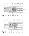
- the positions of included components when a closing operation has been completed are shown more in detail in Fig. 5.
- Fig. 3 thus shows the water discharge valve in an open position, and with the incoming pressure P at the connecting member 4 being less than atmosperic pressure (P ⁇ P atm ).
- a hose 17 is indicated in Fig. 3 with broken lines, connected to the outlet member 3. In such a situation, existing water in the hose 17 may flow back through the water discharge valve and via the connecting member 4 back into the pipe system of the building, unless the water discharge valve has been arranged with a suitable protective device, which can prevent such a return flow.
- valve cone/gasket 5 and 6 which are mounted on a movable shaft 18, by influence from a pressure acting helical spring 19 be moved forward into contact with the valve seat created in the valve housing 2, and thereby close the communication between the water discharge valve and the water supplying pipe system connected to the connecting member 4.
- valve means V formed by the piston shaped members 11, 15 and intermediately located disc shaped valve cone 13 with associated gasket 14, moved from the position illustrated in Fig. 4 to the position shown in Fig. 6, i.e.
- valve cone 13 takes up contact against the dividing member 9 (thereby creating a second non-return valve in excess of previously mentioned spring influenced non-return valve function), and simultaneously opens the second piston shaped member 15 flow communication with the internal part of the tubular shaft 7.
- the second piston shaped member 15 of the valve means V accomplishes simultaneously that substantially the entire valve housing 2 receives communication with surrounding atmosphere at the outside of the external wall 1, and facilitates thus drainage of the valve housing 2 as well as a possibly to the outlet member 3 connected hose 17.
- Important features of the present invention are thus use of the tubular shaft 7 for obtaining communication between surrounding atmosphere and the valve housing 2, as well as use of a valve means V, which during use of the water discharge valve prevents supplied water from flowing through said tubular shaft 7, but which at a pressure loss opens up for a supply of air from surrounding atmosphere via the tubular shaft 7 into the valve housing 2.
- valve means V may e.g. be implemented as a spherical ball shaped member with associated valve seat, but also other solutions can be envisaged by those skilled in the art.
- Gaskets may be arranged in other locations than shown, e.g. by both sides of the disc shaped valve cone 13, and spring means may also be arranged to obtain improved security for a movement of the valve means V to the position shown in Figs. 3 and 6.
- Many modifications are obviously also possible with regard to the arrangement of the channels 16, 16' while still maintaining desired function, i.e. communication between the internal part of the tubular shaft 7 and outside surrounding atmosphere.
- only one such channel may be used, which may comprise of a centrally located hole extending from and through the shown control member 8 to a point where communication is established with the internal part of the tubular shaft 7.
- a hole may e.g. be created by a simple drilling operation.
- the water discharge valve according to the present invention offers substantial functional advantages since same is drained of water in closed position, as well as when a pressure loss occurs in supplying pipe network, without requiring use of an external vacuum valve or similar. Furthermore, when such a pressure loss occurs, return flow into the pipe network of the building is prevented at two from each other separated points within the water discharge valve.
- Use of the tubular shaft 7 as an inlet channel for air from outside surrounding atmosphere results in that included valve functions can be concentrated at a common region of the water discharge valve, adjacent to the inside of a wall 1 through which the water discharge valve extends, a region which normally is free of frost, in difference to known solutions having vacuum valves or similar located by the outside surface of an external wall.
- a further not unimportant advantage is also that the water discharge valve according to the present invention can be manufactured in a simple and cost effective way, which in combination with previously discussed technical advantages is of further advantageous importance.
Landscapes
- Engineering & Computer Science (AREA)
- General Engineering & Computer Science (AREA)
- Health & Medical Sciences (AREA)
- Life Sciences & Earth Sciences (AREA)
- Hydrology & Water Resources (AREA)
- Public Health (AREA)
- Water Supply & Treatment (AREA)
- Mechanical Engineering (AREA)
- Self-Closing Valves And Venting Or Aerating Valves (AREA)
- Lift Valve (AREA)
- Domestic Plumbing Installations (AREA)
- Jet Pumps And Other Pumps (AREA)
- Check Valves (AREA)
- Insulated Conductors (AREA)
- Centrifugal Separators (AREA)
- Containers And Packaging Bodies Having A Special Means To Remove Contents (AREA)
Abstract
Description
- The present invention relates to a water discharge valve intended to be mounted extending through an external wall element and with control means and outlet located by the outside of the wall.
- The invention relates in particular to a water discharge valve of the above stated type, which facilitates that the water discharge valve is completely drained when closed, even if a hose is connected to the outlet member, and which also prevents a return flow back into the supply pipe of the water discharge valve in case that a pressure drop should occur.
- Water discharge valves of the above type are previously known, e.g. from SE, B, 393 845; SE, B, 403 182 and SE, B, 455 434. All these known types are intended to be connected to a supply pipe adjacent to the inside surface of an external wall, and include a control means and outlet by the outside surface of the wall. It is also desirable that such a water discharge valve in closed position is substantially completely drained of water existing outside the valve cone of the water discharge valve, and that same in open position due to a pressure drop in the supply pipe does not allow a return flow, e.g. from a hose connected to the outlet of the water discharge valve.
- The solutions shown in SE, B, 393 845 and SE, B, 403 182 are in order to accomplish the above features equipped with a vacuum valve adjacent to the outlet, which facilitates a supply of air to the outer internal part of the water discharge valve when the water discharge valve is closed, thereby draining the water discharge valve even if a hose is connected. In order to prevent a return flow, if water pressure in the supply pipe ceases or is heavily reduced while the water discharge valve is in use, it is suggested to arrange the valve cone spring loaded against the valve seat, which, in combination with the aforementioned vacuum valve, is suggested to prevent a return flow of water into the pipe system of the building.
- An alternative solution for accomplishing drainage of existing water in the water discharge valve is disclosed in SE, B, 455 434, according to which an additional turning operation of the control means, after establishment of contact between the valve cone and the valve seat, results in an opening operation of a valve means located adjacent to the outer end portion of the water discharge valve, whereby existing water in the water discharge valve can exit through a drainage opening located at the side of the ordinary outlet member.
- Another proposed solution relating to the problem of evacuating water from a water discharge valve and for accomplishing automatic drainage (at least partially) of a hose connected to a water discharge valve is disclosed in SE, B, 457 377. This solution is based on locating a valve means with an air channel as an intermediate member between the outlet of a water discharge valve and a hose, i.e. with the hose connected to the valve means. When the water discharge valve is in an open condition, the air channel is closed by the water pressure acting on an elastic valve member in the valve means, and when the water discharge valve is in a closed condition, the air channel is opened due to the lack of water pressure.
- The object of the present invention is to disclose a water discharge valve, which, without additional external valve means, meets all desired features relating to complete drainage of a water disharge valve in connection with a closing operation, even if a hose should be connected to the outlet member of the water discharge valve.
- Another object is to disclose a water discharge valve which prevents a return flow of water into a supply pipe in case of a pressure drop, as well as to disclose a water discharge valve in which all included valve elements are located immediately adjacent to the inside of an external wall, i.e. having a non-freezing location.
- A further not irrelevant object is to accomplish the above functions in a simple and cost effective way, without any additional external valve means.
- The above objects are accomplished by a water discharge valve according to
claim 1 and related subclaims. - A non-restricting example of an embodiment of a water discharge valve according to the present invention will be more fully described below with reference to the accompanying drawings, in which:-
- Fig. 1 shows a schematical view in longitudinal section of an example of a water discharge valve according to the present invention, showing the water discharge valve in open position;
- Fig. 2 shows a schematical view corresponding to Fig. 1, but with the water discharge valve in closed position, and also illustrating how the water discharge valve is drained of water when closed;
- Fig. 3 shows a schematical view corresponding to Fig. 2, intended to illustrate how the protection against a return flow operates when a pressure drop occurs in a supply pipe;
- Fig. 4 shows an enlarged view in longitudinal section of the part of the water discharge valve where valve cone/valve seat and associated means are arranged, showing said means in the open position as illustrated in Fig. 1;
- Fig. 5 is a view corresponding to Fig. 4, showing said means in the closed position as illustrated in Fig. 2; and
- Fig. 6 is a view corresponding to Fig. 4, showing said means in the position taken up when pressure is not maintained from the water supplying pipe system.
-
- Figs. 1 - 3 show schematically an example of a water discharge valve according to the present invention, which is only intended to serve as an example of an embodiment within the scope of the inventive thought, and also to simplify understanding of the following description. Furthermore, Figs. 4 - 6 show in enlarged scale the components included in the region of the water discharge valve where valve cone/valve seat are arranged, showing the internally relative positions of these components for the various cases of application illustrated in Figs. 1 - 3.
- In the embodiment shown, 1 designates an external wall, wherethrough a longitudinally extending
valve housing 2 extends. Thevalve housing 2 is arranged with anoutlet member 3 adjacent to an outer end portion, and at the opposed end portion arranged with a threaded connectingmember 4, to which a supply pipe (not shown) is intended to be connected. Avalve cone 5 with associatedgasket 6 are located adjacent to the end portion of thevalve housing 2 where the connectingmember 4 is arranged, and a longitudinally extendingtubular shaft 7 is centrally located within thevalve housing 2, arranged to perform an axially extending movement when a control means 8 is manually influenced, said means shown as a member having square cross-section and extending from the outer portion of the water discharge valve. - A rotary movement of the control means 8 in a first direction is arranged to move the
valve cone 5 with associatedgasket 6 away from a bottom portion of thevalve housing 2, which serves as a valve seat, whereby water is supplied to theoutlet member 3. A rotary movement in a second and opposed direction moves thevalve cone 5 in opposite direction and reduces initially the discharged flow, and when contact is established with the valve seat, the water flow is interrupted. - The above described function is generally known for water discharge valves, and locating the valve cone/valve seat adjacent to the portion of the water discharge valve which is close to the inside of a wall element is desirable, e.g. to minimize the risk for damage by freezing.
- When the water discharge valve according to the present invention takes up an open position, as shown in Fig. 1, supplied water flows as indicated by arrows past the gasket/
valve cone member 9, where the water throughchannels 10, 10' passes via grooves taken up in a first piston shapedmember 11 extending through the dividingmember 9. From a space surrounding the first piston shapedmember 11, the water flows viachannels 12, 12' to a space in thevalve housing 2 surrounding thetubular shaft 7, and it is discharged from the water discharge valve through theoutlet member 4. - As shown in Fig. 4, the first piston shaped
member 11 is transformed into a discshaped valve cone 13 having an associatedgasket 14, which are located in an intermediate position to a second piston shapedmember 15 having longitudinally extending grooves, extending into thetubular shaft 7. Said first piston shapedmember 11 and second piston shapedmember 15, and intermediately located disc shapedvalve cone 13 with thegasket 14, constitutes in association with coacting members a valve means, as a complete unit denominated V in Fig. 1 - 3. - When water flows through the water discharge valve, the disc shaped
valve cone 13 with associatedgasket 14 are pressed by the water pressure to a position in which the end portion of thetubular shaft 7 directed towards the connectingmember 4 is closed. Throughflowing water can thus not penetrate into thetubular shaft 7. This is shown more in detail in Fig. 4. - During a closing operation (Fig. 2), the following occurs. When the water supply is interrupted due to the
valve cone 5 with associatedgasket 6 by manual influence applied to thecontrol member 8 being moved to a contact position against the valve seat formed by an end portion of thevalve housing 2, the disc shapedvalve cone 13 being moved to a contact position against the dividingmember 9, and thereby are also the first piston shapedmember 11 and the second piston shapedmember 15 moved, which constitute units integrated with the discshaped valve cone 13. As a result of this movement, the external grooves of the second disc shapedmember 15 will open up communication between the internal part of thetubular shaft 7 viachannels 12,12' to the space within thevalve housing 2 surrounding thetubular shaft 7, and thus also to theoutlet member 3. As shown by the outer portion of the water discharge valve, there arechannels 16,16' formed arranged to create communication between the internal part of thetubular shaft 7 and surrounding external atmosphere, which means that air viasaid channels 16, 16' will flow through the discharge valve as indicated by arrows in Fig. 2, whereby same is drained of water. Such a draining operation will also take place in at least a first part of a possibly to theoutlet member 3 connected hose. The positions of included components when a closing operation has been completed are shown more in detail in Fig. 5. - In case that a pressure loss should occur in the pipe system whereto the water discharge valve is connected, it is important that a return flow can not occur to the pipe system in the building from e.g. a hose connected to the
outlet member 3. Such a situation is illustrated in Figs. 3 and 6 resoectively. - Fig. 3 thus shows the water discharge valve in an open position, and with the incoming pressure P at the connecting
member 4 being less than atmosperic pressure (P < Patm). A hose 17 is indicated in Fig. 3 with broken lines, connected to theoutlet member 3. In such a situation, existing water in the hose 17 may flow back through the water discharge valve and via the connectingmember 4 back into the pipe system of the building, unless the water discharge valve has been arranged with a suitable protective device, which can prevent such a return flow. - As best seen from Fig. 6, in such a situation will the valve cone/
gasket movable shaft 18, by influence from a pressure actinghelical spring 19 be moved forward into contact with the valve seat created in thevalve housing 2, and thereby close the communication between the water discharge valve and the water supplying pipe system connected to the connectingmember 4. Simultaneously is also the valve means V, formed by the piston shapedmembers valve cone 13 with associatedgasket 14, moved from the position illustrated in Fig. 4 to the position shown in Fig. 6, i.e. thevalve cone 13 takes up contact against the dividing member 9 (thereby creating a second non-return valve in excess of previously mentioned spring influenced non-return valve function), and simultaneously opens the second piston shapedmember 15 flow communication with the internal part of thetubular shaft 7. As illustrated by arrows in Fig. 3, this means that air can flow in through thechannels 16,16' to the internal part of thetubular shaft 7, and past thepiston member 15 and via thechannels 12, 12' out into thevalve housing 2. Said air continues through theoutlet member 3 into the hose 17, which thereby also is drained of water, at least with regard to the first part connected to the outlet member. - As disclosed in the above description, communication with connected supplying pipe network will be interrupted at two different points in the water discharge valve, by the
valve cone 5 with associatedgasket 6 close to the connectingmember 4, but also by the valve means V due to the contact of the disc shapedvalve cone 13 against the dividing member 9 (in combination with the position of the first piston shapedmember 11 in relation to the dividing member 9). Accordingly, "double safety" is achieved against return flow into the pipe network of the building. - The second piston shaped
member 15 of the valve means V accomplishes simultaneously that substantially theentire valve housing 2 receives communication with surrounding atmosphere at the outside of theexternal wall 1, and facilitates thus drainage of thevalve housing 2 as well as a possibly to theoutlet member 3 connected hose 17. - Important features of the present invention are thus use of the
tubular shaft 7 for obtaining communication between surrounding atmosphere and thevalve housing 2, as well as use of a valve means V, which during use of the water discharge valve prevents supplied water from flowing through saidtubular shaft 7, but which at a pressure loss opens up for a supply of air from surrounding atmosphere via thetubular shaft 7 into thevalve housing 2. - It should be emphasized, that the above features obviously can be achieved with use of other types of valve means V than shown and described. Accordingly, shown valve means may e.g. be implemented as a spherical ball shaped member with associated valve seat, but also other solutions can be envisaged by those skilled in the art. Gaskets may be arranged in other locations than shown, e.g. by both sides of the disc shaped
valve cone 13, and spring means may also be arranged to obtain improved security for a movement of the valve means V to the position shown in Figs. 3 and 6. Many modifications are obviously also possible with regard to the arrangement of thechannels 16, 16' while still maintaining desired function, i.e. communication between the internal part of thetubular shaft 7 and outside surrounding atmosphere. For example, only one such channel may be used, which may comprise of a centrally located hole extending from and through the showncontrol member 8 to a point where communication is established with the internal part of thetubular shaft 7. Such a hole may e.g. be created by a simple drilling operation. - The water discharge valve according to the present invention offers substantial functional advantages since same is drained of water in closed position, as well as when a pressure loss occurs in supplying pipe network, without requiring use of an external vacuum valve or similar. Furthermore, when such a pressure loss occurs, return flow into the pipe network of the building is prevented at two from each other separated points within the water discharge valve. Use of the
tubular shaft 7 as an inlet channel for air from outside surrounding atmosphere results in that included valve functions can be concentrated at a common region of the water discharge valve, adjacent to the inside of awall 1 through which the water discharge valve extends, a region which normally is free of frost, in difference to known solutions having vacuum valves or similar located by the outside surface of an external wall. - A further not unimportant advantage is also that the water discharge valve according to the present invention can be manufactured in a simple and cost effective way, which in combination with previously discussed technical advantages is of further advantageous importance.
Claims (10)
- Water discharge valve intended to be mounted extending through a wall (1), comprising a longitudinal surrounding valve housing (2) arranged with a connecting member (4) at a first end portion and an outlet member (3) adjacent to a second end portion, and having a control member (8) by said second end portion, arranged when manually influenced via a longitudinally extending tubular shaft (7), surrounded by the valve housing (2), accomplish movement of a valve cone (5) towards/from a valve seat located adjacent to the first end portion of the valve housing (2), characterized in, that the tubular shaft (7) is arranged communicating with an external surrounding atmosphere via at least one channel (16, 16') in connection with an outer region adjacent to the second end portion of the valve housing (2), and that a valve means (V) is arranged to close the opposite end portion of the tubular shaft (7) by pressure influence from water flowing through the valve housing (2) to the outlet member (3), said valve means (V) being arranged to open communication from the internal part of the tubular shaft (7) to the valve housing (2) when said pressure influence is lost.
- Water discharge valve according to claim 1,characterized in, that an opening movement of the valve means (V) intended to facilitate supply of air into the valve housing (2) also simultaneously results in that a portion of the valve housing (2), surrounding the valve cone (5), substantially completely is closed for communication with the part of the valve housing (2) surrounding the tubular shaft (7).
- Water discharge valve according to claim 1 or 2, characterized in that the valve means (V) is arranged as two valve bodies (11, 15) with an intermediate and preferably substantially disc shaped valve cone (13), said valve bodies (11, 15) in a first position being arranged to facilitate a through flow of water from the connecting member (4) via the valve housing (2) to the outlet member (3), and to prevent communication with the internal part of the tubular shaft (7), said valve bodies (11, 15), when moved to a second position, being arranged to open up communication between the internal part of the tubular shaft (7) and surrounding valve housing (2), and to close a portion of the valve housing (2) surrounding the valve cone (5) from communication with the part of the valve housing (2) surrounding the tubular shaft (7).
- Water discharge valve according to claim 1,characterized in, that the valve bodies (11, 15) comprise of two substantially piston shaped members, preferably arranged having one or more longitudinally extending channels or grooves, which facilitate by-flow only when an outer end portion is arranged surrounded by a with respectively piston shaped member (11, 15) co-acting hole.
- Water discharge valve according to any one of claims 1 - 4, characterized in, that the valve cone (5) is arranged spring loaded in order to accomplish a movement from an open position to a contact position against an associated valve seat when pressure loss occurs in the water supplying pipe system connected to the connecting member (4), thereby acting as a second protective means against return flow from the water discharge valve into connected water supplying pipe network.
- Water discharge valve according to any one of claims 1 - 5, characterized in, that the valve cone (5), as well as the valve means (V), are arranged axially sliding movable in relation to a common supporting member, joined to or partly integrated with the end portion of the tubular shaft (7) which is directed towards the connecting member (4) of the water discharge valve.
- Water discharge valve according to claim 6, characterized in, that the common supporting member is arranged with channels (10, 10'; 12, 12') facilitating a water flow from the connecting member (4) to the outlet member (3) when the valve cone (5) and the valve body (V) are located in a position facilitating such a flow, and further facilitating an air flow from the internal part of the tubular shaft (7) when at least the valve body (V) takes up a second position.
- Water discharge valve according to claim 6 or 7, characterized in, that the common supporting member comprises of at least two members joined to each other.
- Water discharge valve according to any one of claims 1 - 8, characterized in, that a dividing member (9) is arranged in an intermediate position to the valve cone (5) and the valve body (V), preferably serving as a co-acting valve seat for the valve body (V), and that said dividing member (9) is arranged in a substantially sealing contact against the internal surface of the valve housing (2), and arranged to be moved in relation to said internal surface in the same extent as the tubular shaft (7) is moved in relation to said valve housing (2) when manually influenced.
- Water discharge valve according to any one of claims 1 - 9, characterized in, that the channel/channels (16, 16') for communication between the internal part of the tubular shaft (7) and surrounding atmosphere comprises of a preferably centrally located hole extending through the control member (8) of the water discharge valve to a point communicating with the internal part of the tubular shaft (7).
Applications Claiming Priority (2)
| Application Number | Priority Date | Filing Date | Title |
|---|---|---|---|
| SE0200913A SE0200913L (en) | 2002-03-22 | 2002-03-22 | water Bouncer |
| SE0200913 | 2002-03-22 |
Publications (3)
| Publication Number | Publication Date |
|---|---|
| EP1347104A2 true EP1347104A2 (en) | 2003-09-24 |
| EP1347104A3 EP1347104A3 (en) | 2004-01-02 |
| EP1347104B1 EP1347104B1 (en) | 2005-10-26 |
Family
ID=20287386
Family Applications (1)
| Application Number | Title | Priority Date | Filing Date |
|---|---|---|---|
| EP03003988A Expired - Lifetime EP1347104B1 (en) | 2002-03-22 | 2003-02-24 | Water discharge valve |
Country Status (6)
| Country | Link |
|---|---|
| EP (1) | EP1347104B1 (en) |
| AT (1) | ATE307931T1 (en) |
| DE (1) | DE60301988T2 (en) |
| DK (1) | DK1347104T3 (en) |
| NO (1) | NO325892B1 (en) |
| SE (1) | SE0200913L (en) |
Cited By (7)
| Publication number | Priority date | Publication date | Assignee | Title |
|---|---|---|---|---|
| DE202005008464U1 (en) * | 2005-05-27 | 2006-11-16 | Interforge Klee Gmbh | Frost proof valve device for public water supply network, has driving unit with bypass line that connects vertical and horizontal sections of connecting channel which join inflow and discharge openings |
| EP1898006A2 (en) | 2006-09-08 | 2008-03-12 | R. Nussbaum AG | Frost-proof drain fitting |
| DE202008003510U1 (en) | 2008-03-12 | 2008-06-05 | Hidde, Axel R., Dr. Ing. | Energy column for outdoor use |
| US7565912B2 (en) | 2005-05-27 | 2009-07-28 | Interforge KleeGmbH | Frost-proof exterior-wall valve |
| WO2013000823A1 (en) * | 2011-06-28 | 2013-01-03 | Pipe Systems Gmbh | Frost-resistant external wall valve for low temperatures |
| CH706690A1 (en) * | 2012-06-28 | 2013-12-31 | Hinni Ag | Main valve for a fire hydrant. |
| WO2016001007A1 (en) | 2014-07-01 | 2016-01-07 | Societe Nouvelle Stn 3R | Device for dispensing antifreeze water |
Families Citing this family (1)
| Publication number | Priority date | Publication date | Assignee | Title |
|---|---|---|---|---|
| DE102007019594B3 (en) * | 2007-04-24 | 2008-11-13 | Schell Gmbh & Co. Kg | Frost-proof armature for e.g. irrigation system, has seal released from mounting hole in valve seat drilling in sealed condition of another seal, where latter seal is released from drilling in hole in sealed condition of former seal |
Citations (4)
| Publication number | Priority date | Publication date | Assignee | Title |
|---|---|---|---|---|
| SE393845B (en) | 1973-08-31 | 1977-05-23 | Ba Installationsutveckling Ab | WATER Ejector INTENDED FOR MOUNTING IN A WALL BETWEEN A HOT SPACE ON ONE SIDE OF THE WALL AND A COLD SPACE ON THE OTHER SIDE OF THE WALL |
| SE403182B (en) | 1974-08-16 | 1978-07-31 | Ba Installationsutveckling Ab | WATER Ejector INTENDED FOR MOUNTING IN A WALL BETWEEN A HOT SPACE AND A COLD SPACE |
| SE455434B (en) | 1986-12-22 | 1988-07-11 | Mattsson Ab F M | FOR FITTING IN AN OUTWALL DETAILED WATER EXHAUST |
| SE457377B (en) | 1987-10-13 | 1988-12-19 | Durgo Ab | VALVE WITH AIR PIPE, SPECIFICALLY FOR WATER EXHAUST |
Family Cites Families (3)
| Publication number | Priority date | Publication date | Assignee | Title |
|---|---|---|---|---|
| BE526349A (en) * | ||||
| US4209033A (en) * | 1975-12-15 | 1980-06-24 | Hirsch Elder F | Vacuum breaker valve |
| US5752542A (en) * | 1996-01-22 | 1998-05-19 | Hoeptner, Iii; Herbert W. | Back flow preventing adjustable valve apparatus |
-
2002
- 2002-03-22 SE SE0200913A patent/SE0200913L/en not_active IP Right Cessation
-
2003
- 2003-02-24 AT AT03003988T patent/ATE307931T1/en not_active IP Right Cessation
- 2003-02-24 EP EP03003988A patent/EP1347104B1/en not_active Expired - Lifetime
- 2003-02-24 DE DE60301988T patent/DE60301988T2/en not_active Expired - Lifetime
- 2003-02-24 DK DK03003988T patent/DK1347104T3/en active
- 2003-03-21 NO NO20031311A patent/NO325892B1/en not_active IP Right Cessation
Patent Citations (4)
| Publication number | Priority date | Publication date | Assignee | Title |
|---|---|---|---|---|
| SE393845B (en) | 1973-08-31 | 1977-05-23 | Ba Installationsutveckling Ab | WATER Ejector INTENDED FOR MOUNTING IN A WALL BETWEEN A HOT SPACE ON ONE SIDE OF THE WALL AND A COLD SPACE ON THE OTHER SIDE OF THE WALL |
| SE403182B (en) | 1974-08-16 | 1978-07-31 | Ba Installationsutveckling Ab | WATER Ejector INTENDED FOR MOUNTING IN A WALL BETWEEN A HOT SPACE AND A COLD SPACE |
| SE455434B (en) | 1986-12-22 | 1988-07-11 | Mattsson Ab F M | FOR FITTING IN AN OUTWALL DETAILED WATER EXHAUST |
| SE457377B (en) | 1987-10-13 | 1988-12-19 | Durgo Ab | VALVE WITH AIR PIPE, SPECIFICALLY FOR WATER EXHAUST |
Cited By (9)
| Publication number | Priority date | Publication date | Assignee | Title |
|---|---|---|---|---|
| DE202005008464U1 (en) * | 2005-05-27 | 2006-11-16 | Interforge Klee Gmbh | Frost proof valve device for public water supply network, has driving unit with bypass line that connects vertical and horizontal sections of connecting channel which join inflow and discharge openings |
| US7565912B2 (en) | 2005-05-27 | 2009-07-28 | Interforge KleeGmbH | Frost-proof exterior-wall valve |
| EP1898006A2 (en) | 2006-09-08 | 2008-03-12 | R. Nussbaum AG | Frost-proof drain fitting |
| DE202008003510U1 (en) | 2008-03-12 | 2008-06-05 | Hidde, Axel R., Dr. Ing. | Energy column for outdoor use |
| DE102008015771A1 (en) | 2008-03-12 | 2010-04-22 | Hidde, Axel R., Dr. Ing. | Energy column for outdoor use |
| WO2013000823A1 (en) * | 2011-06-28 | 2013-01-03 | Pipe Systems Gmbh | Frost-resistant external wall valve for low temperatures |
| CH706690A1 (en) * | 2012-06-28 | 2013-12-31 | Hinni Ag | Main valve for a fire hydrant. |
| EP2679869A1 (en) * | 2012-06-28 | 2014-01-01 | Hinni AG | Main valve for a hydrant |
| WO2016001007A1 (en) | 2014-07-01 | 2016-01-07 | Societe Nouvelle Stn 3R | Device for dispensing antifreeze water |
Also Published As
| Publication number | Publication date |
|---|---|
| EP1347104B1 (en) | 2005-10-26 |
| DK1347104T3 (en) | 2006-02-20 |
| DE60301988D1 (en) | 2005-12-01 |
| SE519524C2 (en) | 2003-03-11 |
| ATE307931T1 (en) | 2005-11-15 |
| SE0200913D0 (en) | 2002-03-22 |
| NO20031311L (en) | 2003-09-23 |
| NO20031311D0 (en) | 2003-03-21 |
| SE0200913L (en) | 2003-03-11 |
| DE60301988T2 (en) | 2006-05-24 |
| NO325892B1 (en) | 2008-08-11 |
| EP1347104A3 (en) | 2004-01-02 |
Similar Documents
| Publication | Publication Date | Title |
|---|---|---|
| US6142172A (en) | Freeze protection device for wall hydrants/faucets | |
| US4178956A (en) | Self-draining sill cock assembly | |
| US6769446B1 (en) | Freeze protection device for wall hydrants/faucets | |
| CA1273264A (en) | Ground hydrant and method for operating same | |
| CA1110521A (en) | Change valve | |
| US7100637B1 (en) | Wall hydrant having backflow preventor | |
| US20070267063A1 (en) | Unloader valve for pressurized fluid delivery system | |
| CA2513961C (en) | Fluid hydrant | |
| EP1347104B1 (en) | Water discharge valve | |
| US20060254647A1 (en) | Yard hydrant with drain port check valve | |
| KR101575958B1 (en) | Water supply system of railway vehicle | |
| US20170363217A1 (en) | Main Stage In-Line Pressure Control Cartridge with Optional Reverse Flow Function | |
| US20080047612A1 (en) | Automatic draining double check vacuum breaker | |
| CA1077803A (en) | Hand pump system for hydraulic motor | |
| US6857442B1 (en) | Freeze protection device for wall hydrants/faucets | |
| CA2513358C (en) | Fluid hydrant with sleeve | |
| US6899012B2 (en) | Fluid flow control valve assembly with independent feedback pressure | |
| US6178988B1 (en) | Hydrant design | |
| US6857446B1 (en) | Flow controlling dual hydrant | |
| US5355907A (en) | Automatic draining back flow preventer for use with hydrant | |
| US6935358B1 (en) | Flow controlling hydrant structure | |
| US11913569B1 (en) | Serviceable ball check valve | |
| KR102231416B1 (en) | Frost protection system for pipelines with injection nozzles | |
| US20240125102A1 (en) | Automatic drain valve | |
| RU2227855C2 (en) | Automatic air valve |
Legal Events
| Date | Code | Title | Description |
|---|---|---|---|
| PUAI | Public reference made under article 153(3) epc to a published international application that has entered the european phase |
Free format text: ORIGINAL CODE: 0009012 |
|
| AK | Designated contracting states |
Kind code of ref document: A2 Designated state(s): AT BE BG CH CY CZ DE DK EE ES FI FR GB GR HU IE IT LI LU MC NL PT SE SI SK TR |
|
| AX | Request for extension of the european patent |
Extension state: AL LT LV MK RO |
|
| PUAL | Search report despatched |
Free format text: ORIGINAL CODE: 0009013 |
|
| AK | Designated contracting states |
Kind code of ref document: A3 Designated state(s): AT BE BG CH CY CZ DE DK EE ES FI FR GB GR HU IE IT LI LU MC NL PT SE SI SK TR |
|
| AX | Request for extension of the european patent |
Extension state: AL LT LV MK RO |
|
| RIC1 | Information provided on ipc code assigned before grant |
Ipc: 7E 03B 7/10 A Ipc: 7F 16K 24/02 B |
|
| 17P | Request for examination filed |
Effective date: 20040630 |
|
| AKX | Designation fees paid |
Designated state(s): AT BE BG CH CY CZ DE DK EE ES FI FR GB GR HU IE IT LI LU MC NL PT SE SI SK TR |
|
| 17Q | First examination report despatched |
Effective date: 20040917 |
|
| GRAP | Despatch of communication of intention to grant a patent |
Free format text: ORIGINAL CODE: EPIDOSNIGR1 |
|
| GRAS | Grant fee paid |
Free format text: ORIGINAL CODE: EPIDOSNIGR3 |
|
| GRAA | (expected) grant |
Free format text: ORIGINAL CODE: 0009210 |
|
| AK | Designated contracting states |
Kind code of ref document: B1 Designated state(s): AT BE BG CH CY CZ DE DK EE ES FI FR GB GR HU IE IT LI LU MC NL PT SE SI SK TR |
|
| PG25 | Lapsed in a contracting state [announced via postgrant information from national office to epo] |
Ref country code: IT Free format text: LAPSE BECAUSE OF FAILURE TO SUBMIT A TRANSLATION OF THE DESCRIPTION OR TO PAY THE FEE WITHIN THE PRESCRIBED TIME-LIMIT;WARNING: LAPSES OF ITALIAN PATENTS WITH EFFECTIVE DATE BEFORE 2007 MAY HAVE OCCURRED AT ANY TIME BEFORE 2007. THE CORRECT EFFECTIVE DATE MAY BE DIFFERENT FROM THE ONE RECORDED. Effective date: 20051026 Ref country code: CZ Free format text: LAPSE BECAUSE OF FAILURE TO SUBMIT A TRANSLATION OF THE DESCRIPTION OR TO PAY THE FEE WITHIN THE PRESCRIBED TIME-LIMIT Effective date: 20051026 Ref country code: NL Free format text: LAPSE BECAUSE OF FAILURE TO SUBMIT A TRANSLATION OF THE DESCRIPTION OR TO PAY THE FEE WITHIN THE PRESCRIBED TIME-LIMIT Effective date: 20051026 Ref country code: LI Free format text: LAPSE BECAUSE OF FAILURE TO SUBMIT A TRANSLATION OF THE DESCRIPTION OR TO PAY THE FEE WITHIN THE PRESCRIBED TIME-LIMIT Effective date: 20051026 Ref country code: SI Free format text: LAPSE BECAUSE OF FAILURE TO SUBMIT A TRANSLATION OF THE DESCRIPTION OR TO PAY THE FEE WITHIN THE PRESCRIBED TIME-LIMIT Effective date: 20051026 Ref country code: CH Free format text: LAPSE BECAUSE OF FAILURE TO SUBMIT A TRANSLATION OF THE DESCRIPTION OR TO PAY THE FEE WITHIN THE PRESCRIBED TIME-LIMIT Effective date: 20051026 Ref country code: SK Free format text: LAPSE BECAUSE OF FAILURE TO SUBMIT A TRANSLATION OF THE DESCRIPTION OR TO PAY THE FEE WITHIN THE PRESCRIBED TIME-LIMIT Effective date: 20051026 Ref country code: AT Free format text: LAPSE BECAUSE OF FAILURE TO SUBMIT A TRANSLATION OF THE DESCRIPTION OR TO PAY THE FEE WITHIN THE PRESCRIBED TIME-LIMIT Effective date: 20051026 |
|
| REG | Reference to a national code |
Ref country code: GB Ref legal event code: FG4D |
|
| REG | Reference to a national code |
Ref country code: CH Ref legal event code: EP |
|
| REG | Reference to a national code |
Ref country code: IE Ref legal event code: FG4D |
|
| REF | Corresponds to: |
Ref document number: 60301988 Country of ref document: DE Date of ref document: 20051201 Kind code of ref document: P |
|
| REG | Reference to a national code |
Ref country code: SE Ref legal event code: TRGR |
|
| PG25 | Lapsed in a contracting state [announced via postgrant information from national office to epo] |
Ref country code: BG Free format text: LAPSE BECAUSE OF FAILURE TO SUBMIT A TRANSLATION OF THE DESCRIPTION OR TO PAY THE FEE WITHIN THE PRESCRIBED TIME-LIMIT Effective date: 20060126 Ref country code: GR Free format text: LAPSE BECAUSE OF FAILURE TO SUBMIT A TRANSLATION OF THE DESCRIPTION OR TO PAY THE FEE WITHIN THE PRESCRIBED TIME-LIMIT Effective date: 20060126 |
|
| PG25 | Lapsed in a contracting state [announced via postgrant information from national office to epo] |
Ref country code: ES Free format text: LAPSE BECAUSE OF FAILURE TO SUBMIT A TRANSLATION OF THE DESCRIPTION OR TO PAY THE FEE WITHIN THE PRESCRIBED TIME-LIMIT Effective date: 20060206 |
|
| REG | Reference to a national code |
Ref country code: DK Ref legal event code: T3 |
|
| PG25 | Lapsed in a contracting state [announced via postgrant information from national office to epo] |
Ref country code: IE Free format text: LAPSE BECAUSE OF NON-PAYMENT OF DUE FEES Effective date: 20060224 |
|
| PG25 | Lapsed in a contracting state [announced via postgrant information from national office to epo] |
Ref country code: LU Free format text: LAPSE BECAUSE OF NON-PAYMENT OF DUE FEES Effective date: 20060228 Ref country code: MC Free format text: LAPSE BECAUSE OF NON-PAYMENT OF DUE FEES Effective date: 20060228 |
|
| PG25 | Lapsed in a contracting state [announced via postgrant information from national office to epo] |
Ref country code: PT Free format text: LAPSE BECAUSE OF FAILURE TO SUBMIT A TRANSLATION OF THE DESCRIPTION OR TO PAY THE FEE WITHIN THE PRESCRIBED TIME-LIMIT Effective date: 20060327 |
|
| NLV1 | Nl: lapsed or annulled due to failure to fulfill the requirements of art. 29p and 29m of the patents act | ||
| PG25 | Lapsed in a contracting state [announced via postgrant information from national office to epo] |
Ref country code: HU Free format text: LAPSE BECAUSE OF FAILURE TO SUBMIT A TRANSLATION OF THE DESCRIPTION OR TO PAY THE FEE WITHIN THE PRESCRIBED TIME-LIMIT Effective date: 20060427 |
|
| REG | Reference to a national code |
Ref country code: CH Ref legal event code: PL |
|
| ET | Fr: translation filed | ||
| PLBE | No opposition filed within time limit |
Free format text: ORIGINAL CODE: 0009261 |
|
| STAA | Information on the status of an ep patent application or granted ep patent |
Free format text: STATUS: NO OPPOSITION FILED WITHIN TIME LIMIT |
|
| 26N | No opposition filed |
Effective date: 20060727 |
|
| REG | Reference to a national code |
Ref country code: IE Ref legal event code: MM4A |
|
| PG25 | Lapsed in a contracting state [announced via postgrant information from national office to epo] |
Ref country code: EE Free format text: LAPSE BECAUSE OF FAILURE TO SUBMIT A TRANSLATION OF THE DESCRIPTION OR TO PAY THE FEE WITHIN THE PRESCRIBED TIME-LIMIT Effective date: 20051026 |
|
| PG25 | Lapsed in a contracting state [announced via postgrant information from national office to epo] |
Ref country code: TR Free format text: LAPSE BECAUSE OF FAILURE TO SUBMIT A TRANSLATION OF THE DESCRIPTION OR TO PAY THE FEE WITHIN THE PRESCRIBED TIME-LIMIT Effective date: 20051026 |
|
| PG25 | Lapsed in a contracting state [announced via postgrant information from national office to epo] |
Ref country code: CY Free format text: LAPSE BECAUSE OF FAILURE TO SUBMIT A TRANSLATION OF THE DESCRIPTION OR TO PAY THE FEE WITHIN THE PRESCRIBED TIME-LIMIT Effective date: 20051026 |
|
| REG | Reference to a national code |
Ref country code: FR Ref legal event code: PLFP Year of fee payment: 14 |
|
| REG | Reference to a national code |
Ref country code: FR Ref legal event code: PLFP Year of fee payment: 15 |
|
| REG | Reference to a national code |
Ref country code: FR Ref legal event code: PLFP Year of fee payment: 16 |
|
| PGFP | Annual fee paid to national office [announced via postgrant information from national office to epo] |
Ref country code: GB Payment date: 20220215 Year of fee payment: 20 Ref country code: FI Payment date: 20220216 Year of fee payment: 20 Ref country code: DK Payment date: 20220222 Year of fee payment: 20 Ref country code: DE Payment date: 20220217 Year of fee payment: 20 |
|
| PGFP | Annual fee paid to national office [announced via postgrant information from national office to epo] |
Ref country code: SE Payment date: 20220222 Year of fee payment: 20 Ref country code: FR Payment date: 20220214 Year of fee payment: 20 Ref country code: BE Payment date: 20220214 Year of fee payment: 20 |
|
| REG | Reference to a national code |
Ref country code: DE Ref legal event code: R071 Ref document number: 60301988 Country of ref document: DE |
|
| REG | Reference to a national code |
Ref country code: DK Ref legal event code: EUP Expiry date: 20230224 |
|
| REG | Reference to a national code |
Ref country code: BE Ref legal event code: MK Effective date: 20230224 |
|
| REG | Reference to a national code |
Ref country code: GB Ref legal event code: PE20 Expiry date: 20230223 |
|
| REG | Reference to a national code |
Ref country code: SE Ref legal event code: EUG |
|
| PG25 | Lapsed in a contracting state [announced via postgrant information from national office to epo] |
Ref country code: GB Free format text: LAPSE BECAUSE OF EXPIRATION OF PROTECTION Effective date: 20230223 |