EP1347093A1 - Propeller for stirring solid-in-liquid suspensions in a treatment tank - Google Patents
Propeller for stirring solid-in-liquid suspensions in a treatment tank Download PDFInfo
- Publication number
- EP1347093A1 EP1347093A1 EP03006006A EP03006006A EP1347093A1 EP 1347093 A1 EP1347093 A1 EP 1347093A1 EP 03006006 A EP03006006 A EP 03006006A EP 03006006 A EP03006006 A EP 03006006A EP 1347093 A1 EP1347093 A1 EP 1347093A1
- Authority
- EP
- European Patent Office
- Prior art keywords
- propeller
- tank
- treatment tank
- central shaft
- baffles
- Prior art date
- Legal status (The legal status is an assumption and is not a legal conclusion. Google has not performed a legal analysis and makes no representation as to the accuracy of the status listed.)
- Withdrawn
Links
- 238000011282 treatment Methods 0.000 title claims abstract description 21
- 238000003756 stirring Methods 0.000 title claims abstract description 7
- 239000006194 liquid suspension Substances 0.000 title claims abstract description 6
- 239000000969 carrier Substances 0.000 claims 1
- 230000033001 locomotion Effects 0.000 description 21
- 239000000725 suspension Substances 0.000 description 15
- 230000009471 action Effects 0.000 description 9
- 239000000835 fiber Substances 0.000 description 8
- 239000000463 material Substances 0.000 description 6
- 239000000123 paper Substances 0.000 description 6
- 238000006243 chemical reaction Methods 0.000 description 5
- 239000007787 solid Substances 0.000 description 5
- 229920002678 cellulose Polymers 0.000 description 4
- 239000001913 cellulose Substances 0.000 description 4
- 238000000926 separation method Methods 0.000 description 4
- 229920003043 Cellulose fiber Polymers 0.000 description 3
- 238000005265 energy consumption Methods 0.000 description 3
- 239000007789 gas Substances 0.000 description 3
- 238000010438 heat treatment Methods 0.000 description 3
- 239000007788 liquid Substances 0.000 description 3
- 238000000034 method Methods 0.000 description 3
- 239000011295 pitch Substances 0.000 description 3
- 230000008569 process Effects 0.000 description 3
- 239000000047 product Substances 0.000 description 3
- 239000000376 reactant Substances 0.000 description 3
- 230000009467 reduction Effects 0.000 description 3
- 239000007900 aqueous suspension Substances 0.000 description 2
- 239000002657 fibrous material Substances 0.000 description 2
- 210000004907 gland Anatomy 0.000 description 2
- 238000004519 manufacturing process Methods 0.000 description 2
- 230000002093 peripheral effect Effects 0.000 description 2
- 239000000126 substance Substances 0.000 description 2
- 206010001497 Agitation Diseases 0.000 description 1
- 229920001131 Pulp (paper) Polymers 0.000 description 1
- 238000013019 agitation Methods 0.000 description 1
- 230000005540 biological transmission Effects 0.000 description 1
- 239000003153 chemical reaction reagent Substances 0.000 description 1
- 238000010276 construction Methods 0.000 description 1
- 238000001816 cooling Methods 0.000 description 1
- 238000005520 cutting process Methods 0.000 description 1
- 239000006185 dispersion Substances 0.000 description 1
- 238000009826 distribution Methods 0.000 description 1
- 230000000694 effects Effects 0.000 description 1
- 239000012467 final product Substances 0.000 description 1
- 239000011087 paperboard Substances 0.000 description 1
- 230000035515 penetration Effects 0.000 description 1
- 238000004537 pulping Methods 0.000 description 1
- 238000011084 recovery Methods 0.000 description 1
- 238000004064 recycling Methods 0.000 description 1
- 229920006395 saturated elastomer Polymers 0.000 description 1
- 238000003892 spreading Methods 0.000 description 1
- 230000007480 spreading Effects 0.000 description 1
- XLYOFNOQVPJJNP-UHFFFAOYSA-N water Substances O XLYOFNOQVPJJNP-UHFFFAOYSA-N 0.000 description 1
Images

Classifications
-
- D—TEXTILES; PAPER
- D21—PAPER-MAKING; PRODUCTION OF CELLULOSE
- D21B—FIBROUS RAW MATERIALS OR THEIR MECHANICAL TREATMENT
- D21B1/00—Fibrous raw materials or their mechanical treatment
- D21B1/04—Fibrous raw materials or their mechanical treatment by dividing raw materials into small particles, e.g. fibres
- D21B1/12—Fibrous raw materials or their mechanical treatment by dividing raw materials into small particles, e.g. fibres by wet methods, by the use of steam
- D21B1/30—Defibrating by other means
- D21B1/34—Kneading or mixing; Pulpers
- D21B1/345—Pulpers
-
- B—PERFORMING OPERATIONS; TRANSPORTING
- B01—PHYSICAL OR CHEMICAL PROCESSES OR APPARATUS IN GENERAL
- B01F—MIXING, e.g. DISSOLVING, EMULSIFYING OR DISPERSING
- B01F23/00—Mixing according to the phases to be mixed, e.g. dispersing or emulsifying
- B01F23/50—Mixing liquids with solids
- B01F23/565—Mixing liquids with solids by introducing liquids in solid material, e.g. to obtain slurries
-
- B—PERFORMING OPERATIONS; TRANSPORTING
- B01—PHYSICAL OR CHEMICAL PROCESSES OR APPARATUS IN GENERAL
- B01F—MIXING, e.g. DISSOLVING, EMULSIFYING OR DISPERSING
- B01F27/00—Mixers with rotary stirring devices in fixed receptacles; Kneaders
- B01F27/80—Mixers with rotary stirring devices in fixed receptacles; Kneaders with stirrers rotating about a substantially vertical axis
- B01F27/808—Mixers with rotary stirring devices in fixed receptacles; Kneaders with stirrers rotating about a substantially vertical axis with stirrers driven from the bottom of the receptacle
-
- B—PERFORMING OPERATIONS; TRANSPORTING
- B01—PHYSICAL OR CHEMICAL PROCESSES OR APPARATUS IN GENERAL
- B01F—MIXING, e.g. DISSOLVING, EMULSIFYING OR DISPERSING
- B01F27/00—Mixers with rotary stirring devices in fixed receptacles; Kneaders
- B01F27/80—Mixers with rotary stirring devices in fixed receptacles; Kneaders with stirrers rotating about a substantially vertical axis
- B01F27/81—Mixers with rotary stirring devices in fixed receptacles; Kneaders with stirrers rotating about a substantially vertical axis the stirrers having central axial inflow and substantially radial outflow
- B01F27/811—Mixers with rotary stirring devices in fixed receptacles; Kneaders with stirrers rotating about a substantially vertical axis the stirrers having central axial inflow and substantially radial outflow with the inflow from one side only, e.g. stirrers placed on the bottom of the receptacle, or used as a bottom discharge pump
-
- B—PERFORMING OPERATIONS; TRANSPORTING
- B01—PHYSICAL OR CHEMICAL PROCESSES OR APPARATUS IN GENERAL
- B01F—MIXING, e.g. DISSOLVING, EMULSIFYING OR DISPERSING
- B01F27/00—Mixers with rotary stirring devices in fixed receptacles; Kneaders
- B01F27/80—Mixers with rotary stirring devices in fixed receptacles; Kneaders with stirrers rotating about a substantially vertical axis
- B01F27/90—Mixers with rotary stirring devices in fixed receptacles; Kneaders with stirrers rotating about a substantially vertical axis with paddles or arms
- B01F27/902—Mixers with rotary stirring devices in fixed receptacles; Kneaders with stirrers rotating about a substantially vertical axis with paddles or arms cooperating with intermeshing elements fixed on the receptacle walls
- B01F27/9021—Mixers with rotary stirring devices in fixed receptacles; Kneaders with stirrers rotating about a substantially vertical axis with paddles or arms cooperating with intermeshing elements fixed on the receptacle walls the elements being vertically arranged, e.g. fixed on the bottom
-
- B—PERFORMING OPERATIONS; TRANSPORTING
- B01—PHYSICAL OR CHEMICAL PROCESSES OR APPARATUS IN GENERAL
- B01F—MIXING, e.g. DISSOLVING, EMULSIFYING OR DISPERSING
- B01F27/00—Mixers with rotary stirring devices in fixed receptacles; Kneaders
- B01F27/80—Mixers with rotary stirring devices in fixed receptacles; Kneaders with stirrers rotating about a substantially vertical axis
- B01F27/92—Mixers with rotary stirring devices in fixed receptacles; Kneaders with stirrers rotating about a substantially vertical axis with helices or screws
- B01F27/921—Mixers with rotary stirring devices in fixed receptacles; Kneaders with stirrers rotating about a substantially vertical axis with helices or screws with helices centrally mounted in the receptacle
- B01F27/9214—Mixers with rotary stirring devices in fixed receptacles; Kneaders with stirrers rotating about a substantially vertical axis with helices or screws with helices centrally mounted in the receptacle with additional mixing elements other than helices; having inner and outer helices; with helices surrounding a guiding tube
-
- D—TEXTILES; PAPER
- D21—PAPER-MAKING; PRODUCTION OF CELLULOSE
- D21B—FIBROUS RAW MATERIALS OR THEIR MECHANICAL TREATMENT
- D21B1/00—Fibrous raw materials or their mechanical treatment
- D21B1/04—Fibrous raw materials or their mechanical treatment by dividing raw materials into small particles, e.g. fibres
- D21B1/12—Fibrous raw materials or their mechanical treatment by dividing raw materials into small particles, e.g. fibres by wet methods, by the use of steam
- D21B1/30—Defibrating by other means
- D21B1/34—Kneading or mixing; Pulpers
- D21B1/345—Pulpers
- D21B1/347—Rotor assemblies
-
- B—PERFORMING OPERATIONS; TRANSPORTING
- B01—PHYSICAL OR CHEMICAL PROCESSES OR APPARATUS IN GENERAL
- B01F—MIXING, e.g. DISSOLVING, EMULSIFYING OR DISPERSING
- B01F27/00—Mixers with rotary stirring devices in fixed receptacles; Kneaders
- B01F27/05—Stirrers
- B01F27/11—Stirrers characterised by the configuration of the stirrers
- B01F27/111—Centrifugal stirrers, i.e. stirrers with radial outlets; Stirrers of the turbine type, e.g. with means to guide the flow
-
- B—PERFORMING OPERATIONS; TRANSPORTING
- B01—PHYSICAL OR CHEMICAL PROCESSES OR APPARATUS IN GENERAL
- B01F—MIXING, e.g. DISSOLVING, EMULSIFYING OR DISPERSING
- B01F27/00—Mixers with rotary stirring devices in fixed receptacles; Kneaders
- B01F27/05—Stirrers
- B01F27/11—Stirrers characterised by the configuration of the stirrers
- B01F27/114—Helically shaped stirrers, i.e. stirrers comprising a helically shaped band or helically shaped band sections
- B01F27/1143—Helically shaped stirrers, i.e. stirrers comprising a helically shaped band or helically shaped band sections screw-shaped, e.g. worms
-
- B—PERFORMING OPERATIONS; TRANSPORTING
- B01—PHYSICAL OR CHEMICAL PROCESSES OR APPARATUS IN GENERAL
- B01F—MIXING, e.g. DISSOLVING, EMULSIFYING OR DISPERSING
- B01F27/00—Mixers with rotary stirring devices in fixed receptacles; Kneaders
- B01F27/05—Stirrers
- B01F27/11—Stirrers characterised by the configuration of the stirrers
- B01F27/19—Stirrers with two or more mixing elements mounted in sequence on the same axis
- B01F27/192—Stirrers with two or more mixing elements mounted in sequence on the same axis with dissimilar elements
-
- B—PERFORMING OPERATIONS; TRANSPORTING
- B01—PHYSICAL OR CHEMICAL PROCESSES OR APPARATUS IN GENERAL
- B01F—MIXING, e.g. DISSOLVING, EMULSIFYING OR DISPERSING
- B01F35/00—Accessories for mixers; Auxiliary operations or auxiliary devices; Parts or details of general application
- B01F35/50—Mixing receptacles
- B01F35/53—Mixing receptacles characterised by the configuration of the interior, e.g. baffles for facilitating the mixing of components
- B01F35/531—Mixing receptacles characterised by the configuration of the interior, e.g. baffles for facilitating the mixing of components with baffles, plates or bars on the wall or the bottom
Definitions
- the invention relates to a propeller for stirring solid-in-liquid suspensions within a treatment tank.
- the propeller is particularly adapted to be used in paper industry to prepare paper pulps.
- the solution often consists in causing strong agitations or channeled motions with the related mass transfers that jointly with proper temperatures and pressures optimize the reactions.
- the installed power is even higher than 200 kW per ton of product present in the container in which the propeller is operating and this high quantity of installed power is mostly required by non organized and channeled motions and the impact of the product under treatment against the surface of the container and the propeller creating inefficient turbulence.
- propellers consisting mainly of a central shaft with a helical or centrifugal impeller keeping the fibrous materials moving in a liquid suspension having a concentration of suspended solids varying from 1 to 6% in the low concentration pulpers while it may vary from 6 to 15% in the high concentration pulpers.
- the action carried out by said equipments consists only in separating the cellulose or scrap fibers and to make homogeneous their suspension in the liquid so as to allow their use in the subsequent paper manufacturing processes.
- the known propellers of the above mentioned kind in their constructional form allowing their most general use, consist of two superposed impellers developed on a vertical plane and connected to two axes causing them to rotate with different angular velocity.
- a first drawback consists in that a considerable portion of the material flow occurs by non channeled and organized motions and with strong impact against the wall of the container causing a decrease of efficiency and high energy consumption.
- Another drawback consists in that their specific constructional shape limits their efficiency to concentrations between 2 to 6% and 6 to 15%.
- a further drawback consists in that their construction and operation limits their use to non pressurized containers, consequently with an operation to temperatures not exceeding 100°C.
- the present invention aims at overcoming said drawbacks and limitations.
- the purpose is to provide a propeller having as main object to be efficient both at low and high concentration of the fibrous suspensions, therefore with concentrations varying from 2 up to 20%.
- Another object of the invention is to provide a propeller causing channeled and organized motion of the fluidic filaments avoiding violent impacts and acting synergistically with the natural motions arising from any action of mechanical thrust in the mass and/or the convective motions arising from the mass heating.
- a further object of the invention is to provide a propeller having considerably lower energy consumption in comparison with the propellers of the prior art.
- Another object is to provide a propeller that can be used in containers of various shapes and capacity between 5 and 100 m 3 .
- a further object of the invention is to provide a propeller reducing the working time in comparison with the propellers of the prior art, the quality of the final product being equal.
- a propeller for stirring solid-in-liquid suspensions inside a treatment tank that according to the main claim is characterized by comprising:
- the propeller of the invention operates inside a treatment tank provided with a bladed plate arranged at the bottom, from which the central shaft is vertically extended.
- the generally radial element of the propeller is facing said bladed plate.
- the generally radial element of the propeller comprises a plurality of radial vanes fixed to the central shaft while the generally axial element comprises a single helical blade wound on the same central shaft.
- the generally axial element may comprise more than one helical blade.
- propeller of the invention allows in view of the principle of motion rationalization, all the other conditions and efficiencies being equal, to install a power being even less than 50% relative to the power required by the propellers of the prior art.
- the propeller of the invention promotes dispersion into the liquid fibrous suspension of the reactants when they are solubilizable solids as well as soluble or insoluble liquids or gases, so as to create a homogeneous mass.
- the propeller promotes and optimizes said effects and allows to operate under conditions of medium-high temperatures warranting heat distribution in view of the channeled and organized motions generated by the propeller.
- this may be activated or accelerated by the pressure conditions under which the propeller may operate. Indeed operation of the propeller is possible up to pressures of 20 bars with temperature up to 200°C in view of the peculiar structure of the active parts and the hydraulically balanced and cooled gland.
- propeller of the invention promotes separation into elementary fibers mainly because of the friction between fibers generated inside the organized flows causing entrainment of each fibrous element sliding relative to the adjacent ones.
- Such an operative mode integrated by reduction of impacts against the container walls, reduces production of fines and the related loss of mechanical features and treated fibrous material.
- propeller of the invention is efficient in treating paper scraps and specifically to obtain separation of ink from the cellulose fibers being the feature of the ink removal process.
- a preferred constructional embodiment provides that the generally axial element of the propeller comprises a single helical blade extending on about two thirds of the central shaft length; in this way it is possible to stir masses preferably but not necessarily consisting of suspensions in water or solutions of reactants of solid and/or cellulose fibers with concentrations varying up to 20%.
- the helical- blade of the propeller has a small angle of inclination to the horizontal and this confers to the propeller the ability to work with better efficiency stocks with higher concentration relative to those that can be worked with propellers of the prior art having the same dimensions.
- the propeller of the invention is shown in figs. 1 and 2 where it is indicated generally with references numeral 1.
- the propeller comprises a generally axial part 6 and a generally radial part 7 that are coaxially arranged one after the other.
- the generally radial part 7 is arranged between the end portion 6a of the generally axial part 6 and the bottom 9 of the tank 2 containing the propeller 1.
- the tank 2 has a spherical shape optimizing the treatments carried out by the propeller during rotation.
- the tank may have any suitable shape such as cylindrical, frustum-conical or other shape.
- the axial part 6 of the propeller is defined by a helical blade 6b with constant pitch, that is wound for about 2/3 of the length on the peripheral surface of a central shaft 5 defining the rotation axis Z of the propeller.
- the axial part 6 has a longitudinal frustum-conical profile converging to the generally radial part 7 and therefore the bottom 9 of the tank 2 with the helical blade 6b inclined relative to horizontal plane ⁇ at a very small angle ⁇ that is preferably but not necessarily comprised between 5° and 25°.
- Such an angle of inclination ⁇ is much smaller than the angles according to which the helical blades of the propellers of the prior art are made and this confers to the propeller 1 of the invention a great ability to convey high concentration suspensions.
- the helical blade 6b has a constant pitch and a single start but in different embodiments it could also have more threads and/or variable pitches.
- each vane has a curved shape whose convexity 15a is facing the direction of rotation 10 of the propeller.
- each vane 15 arranged at the end of the central shaft 5 and facing the bottom 9 of the tank 2, a flat member 16 projecting from both sides of the vane is applied, so that the vane takes a generally T shaped profile when observed in cross section.
- the function of the flat member 16 is to ensure when needed, dimensional reduction of the solid portions of the suspension, since the edge 16b arranged in the motion direction carries out a scissor-like cutting action against the profiles of a bladed plate 9a fixed to the tank bottom 9.
- the propeller 1 is put in a clockwise rotation indicated by arrow 10 by a driving unit, preferably but not necessarily consisting of an electric gear motor keyed to the central axis 5.
- the driving unit may also be constituted by a hydraulically motor with related pump.
- the axis is protected against penetration (leakage) of suspension portions by a gland 8 that when used in pressurized containers at high temperature, is provided with cooling and hydraulically balance 17 of pressure inside the container 2.
- the material under treatment as shown in fig. 2 is channeled and conveyed downwards according to the direction indicated by arrow 11 along the helical duct 6c defined by the helical blade 6b of the axial part 6 until it reaches the radial part 7.
- the rotation of said part conveys the material firstly to the peripheral surface of the tank 2 and then upwards according to the direction indicated by arrow 13.
- the tank 2 is internally provided with baffles 4 of a plain and/or curved shape, preferably but not necessarily arranged at 30° to each other and adapted to contrast rotation of the material being worked.
- a constructional variation provides for use of the propeller in tanks 2 with a temperature higher than the room temperature and under steam- and/or gas pressure.
- the baffles are made with inner channels fed with steam or other heat carrier 3 and being licked by the moving mass, are behaving as the elements of a heat exchanger thus heating the mass under treatment.
- the motions transferred to the aqueous suspension are caused by the axial part 6 of the propeller conveying the material downwards in the direction of arrow 11, until it reaches the radial part 7 that in combination with the action of dimensional reduction given by the flat members 16 acting on the bladed plate 9a, takes the suspension again upwards in the direction indicated by arrow 13 so as to reach again the upper portion of the axial part 6.
- the fibrous suspension undergoes a downward movement inside the axial part 6 and then an upward movement in the gap between the axial part 6 and the tank wall 2.
- baffles 4 have a plain or curved surface and are fixed to the tank wall, angularly spaced one to the other for a constant quantity preferably but not necessarily of 30°.
- the propeller 1 moves the fibrous mass according to channeled motions in synergy with those caused by other actions, such as the convective motions due to mass heating. Moreover the possibility to move greater quantities of suspension with reduce angular velocity in comparison with conventional propellers and lower impacts against the container walls, attains an energy saving so that the installed power may be considerably lower even beyond 50% relative to propellers of the prior art with equivalent output.
- the channeled motions, the lower treatment time and reduced impacts attain a lower wear of the impeller and the container relative to what occurs with the propellers of known type.
- the propeller 1 is put in rotation at a velocity varying from 50 to 150 rpm also as a function of its diameter, through actuators of known type that may indifferently consist of gear motors, hydraulically motors and/or motors provided with belt transmission.
- the spherical shape of the container given as an illustrative but non limiting example, is associated to the propeller of the invention, more particularly to operate at high temperature (up to 200° C), and pressures corresponding to saturated steam.
- the spherical shape for its geometrical characteristics ensures indeed the maximum volume relative to the surface of the container and the minimum thickness relative to the operative pressures needed by the treatment.
- the spherical shape of the tank allows also a better guide of the fibrous suspension in the phase of upwards and downwards movement, because the curved shape of the inner wall of the container guides the suspension during the entire elliptical movement 12.
Abstract
Description
- The invention relates to a propeller for stirring solid-in-liquid suspensions within a treatment tank.
- The propeller is particularly adapted to be used in paper industry to prepare paper pulps.
- It is well known that one of the problems that the chemical and similar industries have frequently to solve, is to obtain homogenous solutions or suspensions, spreading solids and chemical reagents in the masses to be treated, more particularly in the masses with high concentration, so as to make the product uniform and accelerate the reactions.
- The solution often consists in causing strong agitations or channeled motions with the related mass transfers that jointly with proper temperatures and pressures optimize the reactions.
- These problems characterize specifically the cellulose and paper industry that in the various technological applications turns to the following measures:
- operations of pulping cellulose with long and short fibers purchased on the market in the form of bales consisting of dried sheets;
- separation into elementary fibers in the process of recycling scraps of paper and paper board, especially when ink removal is required;
- creation of mass transfer required by delignification reactions, according to which the cellulose fibers in an aqueous suspension are brought to reaction with chemical substances and in the most advanced processes with gaseous reactants such as O2 or O3 under conditions of medium-high temperatures varying from 70 to 200°C and corresponding steam pressures.
- These operations are presently carried out by propellers of various shapes creating uncontrolled motions with consequent high energy consumption.
- The installed power is even higher than 200 kW per ton of product present in the container in which the propeller is operating and this high quantity of installed power is mostly required by non organized and channeled motions and the impact of the product under treatment against the surface of the container and the propeller creating inefficient turbulence.
- It is known that in the cellulose and paper industry propellers are used, consisting mainly of a central shaft with a helical or centrifugal impeller keeping the fibrous materials moving in a liquid suspension having a concentration of suspended solids varying from 1 to 6% in the low concentration pulpers while it may vary from 6 to 15% in the high concentration pulpers.
- The action carried out by said equipments consists only in separating the cellulose or scrap fibers and to make homogeneous their suspension in the liquid so as to allow their use in the subsequent paper manufacturing processes.
- In the frame of said actions, it is important the operation of separating the ink so as to allow recovery of fibers free from pollution due to said ink.
- These specific actions are carried out by an impeller that rotating inside a container causes the mass to be stirred when separation into elementary fibers occurs by the rubbing action between adjacent fibers, said action being a function of time the other conditions being equal.
- The known propellers of the above mentioned kind, in their constructional form allowing their most general use, consist of two superposed impellers developed on a vertical plane and connected to two axes causing them to rotate with different angular velocity.
- Said propellers however have some recognized drawbacks.
- A first drawback consists in that a considerable portion of the material flow occurs by non channeled and organized motions and with strong impact against the wall of the container causing a decrease of efficiency and high energy consumption.
- Another drawback consists in that their specific constructional shape limits their efficiency to concentrations between 2 to 6% and 6 to 15%.
- A further drawback consists in that their construction and operation limits their use to non pressurized containers, consequently with an operation to temperatures not exceeding 100°C.
- The present invention aims at overcoming said drawbacks and limitations.
- More particularly the purpose is to provide a propeller having as main object to be efficient both at low and high concentration of the fibrous suspensions, therefore with concentrations varying from 2 up to 20%.
- Another object of the invention is to provide a propeller causing channeled and organized motion of the fluidic filaments avoiding violent impacts and acting synergistically with the natural motions arising from any action of mechanical thrust in the mass and/or the convective motions arising from the mass heating.
- A further object of the invention is to provide a propeller having considerably lower energy consumption in comparison with the propellers of the prior art.
- Another object is to provide a propeller that can be used in containers of various shapes and capacity between 5 and 100 m3.
- A further object of the invention is to provide a propeller reducing the working time in comparison with the propellers of the prior art, the quality of the final product being equal.
- The above mentioned objects are attained by a propeller for stirring solid-in-liquid suspensions inside a treatment tank that according to the main claim is characterized by comprising:
- a generally axial element consisting of at least a blade with a helical development;
- a generally radial element consisting of a plurality of vanes with generally radial development, said elements belonging to a single central shaft defining a longitudinal rotation axis along which said elements are coaxially arranged one after the other and said generally axial element of said propeller having a frustum-conical shape converging to the bottom of said tank.
- The propeller of the invention operates inside a treatment tank provided with a bladed plate arranged at the bottom, from which the central shaft is vertically extended.
- The generally radial element of the propeller is facing said bladed plate.
- According to a preferred constructional embodiment to be described hereinafter, the generally radial element of the propeller comprises a plurality of radial vanes fixed to the central shaft while the generally axial element comprises a single helical blade wound on the same central shaft.
- In other embodiments the generally axial element may comprise more than one helical blade.
- Advantageously use of the propeller of the invention allows in view of the principle of motion rationalization, all the other conditions and efficiencies being equal, to install a power being even less than 50% relative to the power required by the propellers of the prior art.
- Still advantageously the propeller of the invention promotes dispersion into the liquid fibrous suspension of the reactants when they are solubilizable solids as well as soluble or insoluble liquids or gases, so as to create a homogeneous mass.
- In another advantageous way the propeller promotes and optimizes said effects and allows to operate under conditions of medium-high temperatures warranting heat distribution in view of the channeled and organized motions generated by the propeller.
- More particularly when gases are involved in the reaction, this may be activated or accelerated by the pressure conditions under which the propeller may operate. Indeed operation of the propeller is possible up to pressures of 20 bars with temperature up to 200°C in view of the peculiar structure of the active parts and the hydraulically balanced and cooled gland.
- Advantageous use of the propeller of the invention promotes separation into elementary fibers mainly because of the friction between fibers generated inside the organized flows causing entrainment of each fibrous element sliding relative to the adjacent ones.
- Such an operative mode, integrated by reduction of impacts against the container walls, reduces production of fines and the related loss of mechanical features and treated fibrous material.
- In a particularly advantageous way use of the propeller of the invention is efficient in treating paper scraps and specifically to obtain separation of ink from the cellulose fibers being the feature of the ink removal process.
- Still advantageously a preferred constructional embodiment provides that the generally axial element of the propeller comprises a single helical blade extending on about two thirds of the central shaft length; in this way it is possible to stir masses preferably but not necessarily consisting of suspensions in water or solutions of reactants of solid and/or cellulose fibers with concentrations varying up to 20%.
- Advantageously the helical- blade of the propeller has a small angle of inclination to the horizontal and this confers to the propeller the ability to work with better efficiency stocks with higher concentration relative to those that can be worked with propellers of the prior art having the same dimensions.
- Still advantageously it is possible to reduce, the diameter being equal, the number of revolutions of the propeller still obtaining performances comparable to those of the propellers of the prior art.
- The foregoing objects and corresponding advantages will be better understood by reading the following description of a preferred embodiment of the propeller of the invention making references to the accompanying sheets of drawing in which:
- Fig. 1 is an isometric view of the propeller of the invention; and
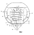
- Fig. 2 is a longitudinal sectional view of the propeller of fig. 1 arranged inside a treatment tank of spherical shape.
- The propeller of the invention is shown in figs. 1 and 2 where it is indicated generally with references numeral 1.
- One can see that the propeller comprises a generally
axial part 6 and a generallyradial part 7 that are coaxially arranged one after the other. - The generally
radial part 7 is arranged between theend portion 6a of the generallyaxial part 6 and thebottom 9 of thetank 2 containing the propeller 1. - More particularly one can see that the
tank 2 has a spherical shape optimizing the treatments carried out by the propeller during rotation. - However it is to be noted that the tank may have any suitable shape such as cylindrical, frustum-conical or other shape. The
axial part 6 of the propeller is defined by ahelical blade 6b with constant pitch, that is wound for about 2/3 of the length on the peripheral surface of acentral shaft 5 defining the rotation axis Z of the propeller. - It is also to be noted that the
axial part 6 has a longitudinal frustum-conical profile converging to the generallyradial part 7 and therefore thebottom 9 of thetank 2 with thehelical blade 6b inclined relative to horizontal plane π at a very small angle α that is preferably but not necessarily comprised between 5° and 25°. - Such an angle of inclination α is much smaller than the angles according to which the helical blades of the propellers of the prior art are made and this confers to the propeller 1 of the invention a great ability to convey high concentration suspensions.
- The
helical blade 6b has a constant pitch and a single start but in different embodiments it could also have more threads and/or variable pitches. - With regard to the generally
radial part 7, one can see that it comprises a plurality ofvanes 15 that are radially fixed to the samecentral shaft 5 on which also thehelical blade 6b is wound, and each vane has a curved shape whoseconvexity 15a is facing the direction ofrotation 10 of the propeller. - One can also see that at the
edge 15b of eachvane 15 arranged at the end of thecentral shaft 5 and facing thebottom 9 of thetank 2, aflat member 16 projecting from both sides of the vane is applied, so that the vane takes a generally T shaped profile when observed in cross section. - The function of the
flat member 16 is to ensure when needed, dimensional reduction of the solid portions of the suspension, since theedge 16b arranged in the motion direction carries out a scissor-like cutting action against the profiles of abladed plate 9a fixed to thetank bottom 9. - The propeller 1 is put in a clockwise rotation indicated by
arrow 10 by a driving unit, preferably but not necessarily consisting of an electric gear motor keyed to thecentral axis 5. - The driving unit may also be constituted by a hydraulically motor with related pump.
- The axis is protected against penetration (leakage) of suspension portions by a
gland 8 that when used in pressurized containers at high temperature, is provided with cooling and hydraulicallybalance 17 of pressure inside thecontainer 2. - In operation during rotation of the propeller 1, the material under treatment as shown in fig. 2, is channeled and conveyed downwards according to the direction indicated by
arrow 11 along thehelical duct 6c defined by thehelical blade 6b of theaxial part 6 until it reaches theradial part 7. - The rotation of said part conveys the material firstly to the peripheral surface of the
tank 2 and then upwards according to the direction indicated byarrow 13. - In order to avoid that the material is being rotated in the same direction of the propeller 1, the
tank 2 is internally provided withbaffles 4 of a plain and/or curved shape, preferably but not necessarily arranged at 30° to each other and adapted to contrast rotation of the material being worked. - A constructional variation provides for use of the propeller in
tanks 2 with a temperature higher than the room temperature and under steam- and/or gas pressure. In such a case the baffles are made with inner channels fed with steam orother heat carrier 3 and being licked by the moving mass, are behaving as the elements of a heat exchanger thus heating the mass under treatment. - The motions transferred to the aqueous suspension are caused by the
axial part 6 of the propeller conveying the material downwards in the direction ofarrow 11, until it reaches theradial part 7 that in combination with the action of dimensional reduction given by theflat members 16 acting on thebladed plate 9a, takes the suspension again upwards in the direction indicated byarrow 13 so as to reach again the upper portion of theaxial part 6. - In this way the fibrous suspension undergoes a downward movement inside the
axial part 6 and then an upward movement in the gap between theaxial part 6 and thetank wall 2. - All together an elliptical
continuous movement 12 diagrammatically shown in fig. 2 is obtained, developed on the vertical plane and in view of the peculiar arrangement of thebaffles 4, causes channeled and organized crescent-like movements. - More particularly the
baffles 4 have a plain or curved surface and are fixed to the tank wall, angularly spaced one to the other for a constant quantity preferably but not necessarily of 30°. - The downward converging frustum-conical shape of the
axial part 6 and the small angle of inclination α to the horizontal of thehelical blade 6b promote theelliptical movement 12 of the fibrous suspension shown in fig. 2. - Advantageously this allows to treat suspensions with concentrations that may reach and even exceed 20% and therefore higher than those obtainable with the known stirring devices.
- The propeller 1 moves the fibrous mass according to channeled motions in synergy with those caused by other actions, such as the convective motions due to mass heating. Moreover the possibility to move greater quantities of suspension with reduce angular velocity in comparison with conventional propellers and lower impacts against the container walls, attains an energy saving so that the installed power may be considerably lower even beyond 50% relative to propellers of the prior art with equivalent output.
- The channeled motions, the lower treatment time and reduced impacts attain a lower wear of the impeller and the container relative to what occurs with the propellers of known type.
- The propeller 1 is put in rotation at a velocity varying from 50 to 150 rpm also as a function of its diameter, through actuators of known type that may indifferently consist of gear motors, hydraulically motors and/or motors provided with belt transmission.
- The spherical shape of the container given as an illustrative but non limiting example, is associated to the propeller of the invention, more particularly to operate at high temperature (up to 200° C), and pressures corresponding to saturated steam.
- The spherical shape for its geometrical characteristics ensures indeed the maximum volume relative to the surface of the container and the minimum thickness relative to the operative pressures needed by the treatment.
- The spherical shape of the tank allows also a better guide of the fibrous suspension in the phase of upwards and downwards movement, because the curved shape of the inner wall of the container guides the suspension during the entire
elliptical movement 12. - In view of the foregoing one can understand that the propeller of the invention attains all the intended objects.
- It is obvious that in the constructional stage the assembly of propeller and container may be carried out also with shapes different from the disclosure and in any dimension as a function of the user's requirements.
- It is to be understood that such possible variations when falling within the scope of the appended claims, are to be considered protected by the preset patent.
Claims (15)
- A propeller (1) for stirring solid-in-liquid suspension inside a treatment tank (2) characterized by comprising:a generally axial element (6) consisting of at least a blade (6b) with helical development;a generally radial element (7) consisting of a plurality of vanes (15) with generally radial development, said elements (6, 7) belonging to a single central shaft (5) defining a longitudinal rotation axis (Z) along which said elements (6, 7) are coaxially arranged one after the other and said generally axial element (6) of said propeller (1) having a frustum-conical shape converging to the bottom of said tank (2).
- A treatment tank (2) adapted to receive the propeller (1) according to claim 1), characterized by comprising a bladed plate (9a) arranged at the bottom (9) to which said generally radial element (7) of said propeller (1) is facing, said central shaft (5) of the propeller (1) being vertically extended from said bottom (9) of said tank (2).
- The propeller (1) according to claim 1) characterized in that said generally radial element (7) comprises a plurality of radial vanes (15) fixed to said central shaft (5), each radial vane (15) having a curved shape with convexity (15a) facing the direction of rotation (10) of said propeller (1).
- The tank (2) according to claim 2) characterized in that said bladed plate (9a) cooperates with a flat member (16) provided on the edge (15b) of each radial vane (15) of said propeller (1) and facing said bladed plate (9a).
- The tank (2) according to claim 4) characterized in that each of said flat members (16) is projecting at both sides from the corresponding radial vane (15) having a T shape when seen in cross section.
- The propeller (1) according to claim 1) characterized in that said generally axial element (6) is developed for at least half the length of said central shaft (5).
- The propeller (1) according to claim 6) characterized in that said at least a helical blade (6b) is inclined relative to a horizontal plane (π) at an angle between 5° and 25°.
- The propeller (1) according to claim 1) characterized in that said central shaft (5) is coupled to driving means adapted to put it into rotation at a velocity between 50 and 150 rpm.
- The treatment tank (2) according to claim 2) characterized by having baffles (4) applied to the internal lateral surface of said tank (2) and projecting inside said tank (2).
- The treatment tank (2) according to claim 9) characterized in that said baffles (4) have a plain surface.
- The treatment tank (2) according to claim 9) characterized in that said baffles (4) have a curved surface.
- The treatment tank (2) according to claim 9) characterized in that said baffles (4) are spaced angularly one to the other at an angle of 30°.
- The treatment tank (2) according to claim 9) characterized in that one or more of said baffles (4) have inner channels connected to heat carriers (3).
- The treatment tank (2) according to claims 2), 4) or 9) to 13) characterized by having spherical shape.
- The treatment tank (2) according to claims 2), 4) or 9) to 13) characterized by having a cylindrical shape.
Applications Claiming Priority (2)
| Application Number | Priority Date | Filing Date | Title |
|---|---|---|---|
| IT2002VI000048A ITVI20020048A1 (en) | 2002-03-19 | 2002-03-19 | PROPULSOR FOR THE STIRRING OF SUSPENSIONS OF SOLIDS INSIDE A TREATMENT TANK |
| ITVI20020048 | 2002-03-19 |
Publications (1)
| Publication Number | Publication Date |
|---|---|
| EP1347093A1 true EP1347093A1 (en) | 2003-09-24 |
Family
ID=27773210
Family Applications (1)
| Application Number | Title | Priority Date | Filing Date |
|---|---|---|---|
| EP03006006A Withdrawn EP1347093A1 (en) | 2002-03-19 | 2003-03-18 | Propeller for stirring solid-in-liquid suspensions in a treatment tank |
Country Status (3)
| Country | Link |
|---|---|
| US (1) | US20040008574A1 (en) |
| EP (1) | EP1347093A1 (en) |
| IT (1) | ITVI20020048A1 (en) |
Cited By (6)
| Publication number | Priority date | Publication date | Assignee | Title |
|---|---|---|---|---|
| FR2883704A1 (en) * | 2005-04-05 | 2006-10-06 | Vmi Sa | Machine for mixing and kneading a flour and water-based dough for food products has helical upper mixing tool and lower one with rotary arm(s) |
| WO2008099180A1 (en) | 2007-02-16 | 2008-08-21 | Brunob Ii B. V. | Apparatus for and methods of mixing and dispensing liquid or powdery samples |
| EP2105201A1 (en) * | 2008-03-28 | 2009-09-30 | Robert Bosch GmbH | Device and method for mixing viscous or plastic media |
| CN104372702A (en) * | 2014-12-15 | 2015-02-25 | 济南大学 | Pulper low in power consumption and noise |
| EP2990373A1 (en) * | 2014-08-29 | 2016-03-02 | Sidel S.p.a. Con Socio Unico | A fluid-agitating tank assembly for a machine for filling containers |
| CN111117675A (en) * | 2020-01-07 | 2020-05-08 | 山东理工大学 | Sectional spiral stirring type biomass pyrolysis liquefaction system |
Families Citing this family (4)
| Publication number | Priority date | Publication date | Assignee | Title |
|---|---|---|---|---|
| CN106948204A (en) * | 2017-03-24 | 2017-07-14 | 合肥悦兰信息技术有限公司 | A kind of crushing mechanism of vertical hydrabrusher |
| CN108144466B (en) * | 2017-12-14 | 2020-04-07 | 长安大学 | Laboratory high shear dispersion emulsion machine |
| CN114432950B (en) * | 2022-04-11 | 2022-06-14 | 山东黄金矿业科技有限公司充填工程实验室分公司 | Stirring and mixing device for production of mine filling material |
| CN115709011A (en) * | 2022-11-09 | 2023-02-24 | 珠海奥维数码科技有限公司 | Production method of high-temperature yellowing resistant UV ink |
Citations (8)
| Publication number | Priority date | Publication date | Assignee | Title |
|---|---|---|---|---|
| FR1379171A (en) * | 1963-12-06 | 1964-11-20 | Ed Jones Corp | Crusher |
| US3843063A (en) * | 1973-02-06 | 1974-10-22 | Morden Machines Co | Shredding and defiberizing machine |
| EP0117716A2 (en) * | 1983-02-28 | 1984-09-05 | The Black Clawson Company | Apparatus for pulping paper, and a rotor therefor |
| EP0122991A2 (en) * | 1982-08-12 | 1984-10-31 | The Black Clawson Company | Apparatus and method for pulping paper making stock at high consistencies |
| EP0126632A2 (en) * | 1983-05-18 | 1984-11-28 | The Black Clawson Company | Pulping apparatus and method |
| EP0279022A1 (en) * | 1987-01-20 | 1988-08-24 | Sulzer-Escher Wyss Gmbh | Process and installation for pulping paper stock |
| US5358185A (en) * | 1992-12-05 | 1994-10-25 | J. M. Voith Gmbh | Method of digesting waste paper |
| US5772131A (en) * | 1995-06-05 | 1998-06-30 | Comer Spa | Kneader for paper stuff |
Family Cites Families (13)
| Publication number | Priority date | Publication date | Assignee | Title |
|---|---|---|---|---|
| US3690621A (en) * | 1969-03-04 | 1972-09-12 | Itsuko Tanaka | Agitator |
| JPS5023773U (en) * | 1973-03-28 | 1975-03-17 | ||
| DE3376436D1 (en) * | 1983-03-18 | 1988-06-01 | Sunds Defibrator | Reactor to perform chemical reactions with dimensional reduction of solid materials |
| SE448009B (en) * | 1983-09-16 | 1987-01-12 | Kamyr Ab | MATERIAL OUTPUT DEVICE |
| IT8520484V0 (en) * | 1985-01-14 | 1985-01-14 | Ica Spa | SPAPOLATORE FOR PAPER AND / OR SIMILAR WASTE PRODUCTS. |
| SE461134B (en) * | 1986-11-18 | 1990-01-15 | Hedemora Ab | PROCEDURE AND DEVICE FOR MIXING CHEMICALS IN FIBER MASS |
| US4826398A (en) * | 1987-07-06 | 1989-05-02 | Kamyr Ab | Medium consistency pump with self-feeding |
| IT1226956B (en) * | 1988-07-11 | 1991-02-26 | Tiziano Faccia | REFINEMENTS TO A MIXER ESPECIALLY FOR FIBROUS PRODUCTS IN THE ZOOTECHNICAL AREA |
| FI86600C (en) * | 1990-04-04 | 1992-09-25 | Outokumpu Oy | Methods for mixing liquid, solid and gas and separating out of the liquid and gas or gas and solid |
| FI97024C (en) * | 1991-07-15 | 1996-10-10 | Ahlstroem Oy | Method and apparatus for separating gas from a gas-containing material |
| IT1255016B (en) * | 1992-03-27 | 1995-10-13 | Sorema Srl | CONICAL BOTTOM SILO, PARTICULARLY FOR PLASTIC MATERIAL AND SMALL PIECE RUBBER WITH HIGH ELASTICITY CHARACTERISTICS |
| US5453159A (en) * | 1993-11-04 | 1995-09-26 | International Paper Company | Deinking of recycled pulp |
| KR100468599B1 (en) * | 2002-01-22 | 2005-02-02 | (주)선보정밀 | Apparatus for disposing garbage of food |
-
2002
- 2002-03-19 IT IT2002VI000048A patent/ITVI20020048A1/en unknown
-
2003
- 2003-03-18 EP EP03006006A patent/EP1347093A1/en not_active Withdrawn
- 2003-03-18 US US10/390,158 patent/US20040008574A1/en not_active Abandoned
Patent Citations (8)
| Publication number | Priority date | Publication date | Assignee | Title |
|---|---|---|---|---|
| FR1379171A (en) * | 1963-12-06 | 1964-11-20 | Ed Jones Corp | Crusher |
| US3843063A (en) * | 1973-02-06 | 1974-10-22 | Morden Machines Co | Shredding and defiberizing machine |
| EP0122991A2 (en) * | 1982-08-12 | 1984-10-31 | The Black Clawson Company | Apparatus and method for pulping paper making stock at high consistencies |
| EP0117716A2 (en) * | 1983-02-28 | 1984-09-05 | The Black Clawson Company | Apparatus for pulping paper, and a rotor therefor |
| EP0126632A2 (en) * | 1983-05-18 | 1984-11-28 | The Black Clawson Company | Pulping apparatus and method |
| EP0279022A1 (en) * | 1987-01-20 | 1988-08-24 | Sulzer-Escher Wyss Gmbh | Process and installation for pulping paper stock |
| US5358185A (en) * | 1992-12-05 | 1994-10-25 | J. M. Voith Gmbh | Method of digesting waste paper |
| US5772131A (en) * | 1995-06-05 | 1998-06-30 | Comer Spa | Kneader for paper stuff |
Cited By (11)
| Publication number | Priority date | Publication date | Assignee | Title |
|---|---|---|---|---|
| FR2883704A1 (en) * | 2005-04-05 | 2006-10-06 | Vmi Sa | Machine for mixing and kneading a flour and water-based dough for food products has helical upper mixing tool and lower one with rotary arm(s) |
| WO2006106225A1 (en) * | 2005-04-05 | 2006-10-12 | Vmi | Device for continuously mixing a food dough provided with two types of superimposed mixing tools and a side discharge |
| US7717612B2 (en) | 2005-04-05 | 2010-05-18 | Vmi | Device for continuously mixing a food dough provided with two types of superimposed mixing tools and a side discharge |
| WO2008099180A1 (en) | 2007-02-16 | 2008-08-21 | Brunob Ii B. V. | Apparatus for and methods of mixing and dispensing liquid or powdery samples |
| AU2008215918B2 (en) * | 2007-02-16 | 2012-05-17 | Corn Products Development, Inc. | Apparatus for and methods of mixing and dispensing liquid or powdery samples |
| EP2105201A1 (en) * | 2008-03-28 | 2009-09-30 | Robert Bosch GmbH | Device and method for mixing viscous or plastic media |
| EP2990373A1 (en) * | 2014-08-29 | 2016-03-02 | Sidel S.p.a. Con Socio Unico | A fluid-agitating tank assembly for a machine for filling containers |
| US10292525B2 (en) | 2014-08-29 | 2019-05-21 | Sidel S.P.A. Con Socio Unico | Fluid-agitating tank assembly for a machine for filling containers |
| CN104372702A (en) * | 2014-12-15 | 2015-02-25 | 济南大学 | Pulper low in power consumption and noise |
| CN111117675A (en) * | 2020-01-07 | 2020-05-08 | 山东理工大学 | Sectional spiral stirring type biomass pyrolysis liquefaction system |
| CN111117675B (en) * | 2020-01-07 | 2021-03-19 | 山东理工大学 | Sectional spiral stirring type biomass pyrolysis liquefaction system |
Also Published As
| Publication number | Publication date |
|---|---|
| ITVI20020048A1 (en) | 2003-09-19 |
| US20040008574A1 (en) | 2004-01-15 |
Similar Documents
| Publication | Publication Date | Title |
|---|---|---|
| US5575559A (en) | Mixer for mixing multi-phase fluids | |
| AU647858B2 (en) | Ozone bleaching of high consistency pulp | |
| EP1347093A1 (en) | Propeller for stirring solid-in-liquid suspensions in a treatment tank | |
| US7398963B2 (en) | Apparatus and method for diffused aeration | |
| EP2950915B1 (en) | Stirred tank reactor | |
| US4838704A (en) | Mixer apparatus | |
| US3734469A (en) | Reactor vessel and up-down mixer | |
| US3342425A (en) | Paper machinery | |
| KR102408877B1 (en) | Rotor and stirring device | |
| EP0807210A1 (en) | A continuous dynamic mixing system and methods for operating such system | |
| US6986829B2 (en) | Process and container for stacking high-consistency stock | |
| CN102281952A (en) | A mixing impeller | |
| EP0139633B1 (en) | Reactor to perform chemical reactions with dimensional reduction of solid materials | |
| US6053441A (en) | Toroidal flow pulper for difficult materials | |
| JP3433919B2 (en) | Stock control device | |
| US9512560B2 (en) | Short oxygen delignification method | |
| US4301846A (en) | Machine for producing wood shavings from chips | |
| PL78727B1 (en) | ||
| EP0323749A2 (en) | Method and means for facilitating the discharge of a drop leg or the like and treating pulp in said space | |
| CN115382427A (en) | Stirring device for pulping machine and pulping machine | |
| WO2016069325A1 (en) | Dynamic mixing assembly with improved baffle design | |
| KR101340712B1 (en) | Mix apparatus including draft tube | |
| CN218307427U (en) | Stirring device for pulping machine and pulping machine | |
| RU2156648C1 (en) | Rotary disperser | |
| CA1222156A (en) | Reactor to perform chemical reactions with dimensional reduction of solid materials |
Legal Events
| Date | Code | Title | Description |
|---|---|---|---|
| PUAI | Public reference made under article 153(3) epc to a published international application that has entered the european phase |
Free format text: ORIGINAL CODE: 0009012 |
|
| AK | Designated contracting states |
Kind code of ref document: A1 Designated state(s): AT BE BG CH CY CZ DE DK EE ES FI FR GB GR HU IE IT LI LU MC NL PT RO SE SI SK TR |
|
| AX | Request for extension of the european patent |
Extension state: AL LT LV MK RO |
|
| RAP1 | Party data changed (applicant data changed or rights of an application transferred) |
Owner name: NACO TECHNOLOGIES SPA |
|
| RAP1 | Party data changed (applicant data changed or rights of an application transferred) |
Owner name: COMER SPA Owner name: NACO TECHNOLOGIES SPA |
|
| REG | Reference to a national code |
Ref country code: DE Ref legal event code: 8566 |
|
| PUAJ | Public notification under rule 129 epc |
Free format text: ORIGINAL CODE: 0009425 |
|
| 32PN | Public notification |
Free format text: COMMUNICATION PURSUANT TO RULE 85A AND 85B EPC (EPO FORM 1149 DATED 24-06-2004) |
|
| PUAJ | Public notification under rule 129 epc |
Free format text: ORIGINAL CODE: 0009425 |
|
| 32PN | Public notification | ||
| STAA | Information on the status of an ep patent application or granted ep patent |
Free format text: STATUS: THE APPLICATION IS DEEMED TO BE WITHDRAWN |
|
| 18D | Application deemed to be withdrawn |
Effective date: 20050908 |