EP1346959A1 - Coated optical fiber and production method therefor - Google Patents
Coated optical fiber and production method therefor Download PDFInfo
- Publication number
- EP1346959A1 EP1346959A1 EP01272317A EP01272317A EP1346959A1 EP 1346959 A1 EP1346959 A1 EP 1346959A1 EP 01272317 A EP01272317 A EP 01272317A EP 01272317 A EP01272317 A EP 01272317A EP 1346959 A1 EP1346959 A1 EP 1346959A1
- Authority
- EP
- European Patent Office
- Prior art keywords
- optical fiber
- layer coating
- coating
- guide roller
- glass
- Prior art date
- Legal status (The legal status is an assumption and is not a legal conclusion. Google has not performed a legal analysis and makes no representation as to the accuracy of the status listed.)
- Withdrawn
Links
- 239000013307 optical fiber Substances 0.000 title claims abstract description 165
- 238000004519 manufacturing process Methods 0.000 title claims abstract description 15
- 238000000576 coating method Methods 0.000 claims abstract description 186
- 239000011248 coating agent Substances 0.000 claims abstract description 180
- 239000011521 glass Substances 0.000 claims abstract description 73
- 239000000835 fiber Substances 0.000 claims abstract description 23
- 239000000463 material Substances 0.000 claims description 32
- 239000000178 monomer Substances 0.000 claims description 31
- 239000011347 resin Substances 0.000 claims description 30
- 229920005989 resin Polymers 0.000 claims description 30
- 125000000623 heterocyclic group Chemical group 0.000 claims description 7
- OKTJSMMVPCPJKN-UHFFFAOYSA-N Carbon Chemical compound [C] OKTJSMMVPCPJKN-UHFFFAOYSA-N 0.000 claims description 5
- 229910052799 carbon Inorganic materials 0.000 claims description 5
- 125000001570 methylene group Chemical group [H]C([H])([*:1])[*:2] 0.000 claims description 5
- 230000010287 polarization Effects 0.000 abstract description 5
- 239000006185 dispersion Substances 0.000 abstract description 4
- 238000000034 method Methods 0.000 description 16
- 230000005540 biological transmission Effects 0.000 description 10
- 230000002349 favourable effect Effects 0.000 description 9
- 238000012216 screening Methods 0.000 description 9
- 238000012360 testing method Methods 0.000 description 9
- 230000000052 comparative effect Effects 0.000 description 6
- 239000004721 Polyphenylene oxide Substances 0.000 description 5
- UHESRSKEBRADOO-UHFFFAOYSA-N ethyl carbamate;prop-2-enoic acid Chemical compound OC(=O)C=C.CCOC(N)=O UHESRSKEBRADOO-UHFFFAOYSA-N 0.000 description 5
- 230000001678 irradiating effect Effects 0.000 description 5
- 229920000570 polyether Polymers 0.000 description 5
- 238000005253 cladding Methods 0.000 description 4
- 238000004891 communication Methods 0.000 description 4
- 230000003247 decreasing effect Effects 0.000 description 4
- 239000003085 diluting agent Substances 0.000 description 4
- 238000006073 displacement reaction Methods 0.000 description 4
- 239000000203 mixture Substances 0.000 description 4
- VYPSYNLAJGMNEJ-UHFFFAOYSA-N Silicium dioxide Chemical compound O=[Si]=O VYPSYNLAJGMNEJ-UHFFFAOYSA-N 0.000 description 3
- 238000005299 abrasion Methods 0.000 description 3
- 238000006243 chemical reaction Methods 0.000 description 3
- 230000003287 optical effect Effects 0.000 description 3
- 238000003825 pressing Methods 0.000 description 3
- PSGCQDPCAWOCSH-UHFFFAOYSA-N (4,7,7-trimethyl-3-bicyclo[2.2.1]heptanyl) prop-2-enoate Chemical compound C1CC2(C)C(OC(=O)C=C)CC1C2(C)C PSGCQDPCAWOCSH-UHFFFAOYSA-N 0.000 description 2
- JWYVGKFDLWWQJX-UHFFFAOYSA-N 1-ethenylazepan-2-one Chemical compound C=CN1CCCCCC1=O JWYVGKFDLWWQJX-UHFFFAOYSA-N 0.000 description 2
- XLPJNCYCZORXHG-UHFFFAOYSA-N 1-morpholin-4-ylprop-2-en-1-one Chemical compound C=CC(=O)N1CCOCC1 XLPJNCYCZORXHG-UHFFFAOYSA-N 0.000 description 2
- CSCPPACGZOOCGX-UHFFFAOYSA-N Acetone Chemical compound CC(C)=O CSCPPACGZOOCGX-UHFFFAOYSA-N 0.000 description 2
- HRPVXLWXLXDGHG-UHFFFAOYSA-N Acrylamide Chemical compound NC(=O)C=C HRPVXLWXLXDGHG-UHFFFAOYSA-N 0.000 description 2
- 239000004925 Acrylic resin Substances 0.000 description 2
- WHNWPMSKXPGLAX-UHFFFAOYSA-N N-Vinyl-2-pyrrolidone Chemical compound C=CN1CCCC1=O WHNWPMSKXPGLAX-UHFFFAOYSA-N 0.000 description 2
- QAOWNCQODCNURD-UHFFFAOYSA-N Sulfuric acid Chemical compound OS(O)(=O)=O QAOWNCQODCNURD-UHFFFAOYSA-N 0.000 description 2
- 150000002009 diols Chemical class 0.000 description 2
- 239000000428 dust Substances 0.000 description 2
- 239000006087 Silane Coupling Agent Substances 0.000 description 1
- NIXOWILDQLNWCW-UHFFFAOYSA-N acrylic acid group Chemical group C(C=C)(=O)O NIXOWILDQLNWCW-UHFFFAOYSA-N 0.000 description 1
- 125000001931 aliphatic group Chemical group 0.000 description 1
- 239000012298 atmosphere Substances 0.000 description 1
- 238000005229 chemical vapour deposition Methods 0.000 description 1
- 238000013329 compounding Methods 0.000 description 1
- 239000000470 constituent Substances 0.000 description 1
- 238000004132 cross linking Methods 0.000 description 1
- 238000000151 deposition Methods 0.000 description 1
- 230000002542 deteriorative effect Effects 0.000 description 1
- 238000007865 diluting Methods 0.000 description 1
- 238000009826 distribution Methods 0.000 description 1
- 230000000694 effects Effects 0.000 description 1
- 239000003822 epoxy resin Substances 0.000 description 1
- 238000011156 evaluation Methods 0.000 description 1
- 238000012681 fiber drawing Methods 0.000 description 1
- 238000010438 heat treatment Methods 0.000 description 1
- 238000007373 indentation Methods 0.000 description 1
- 150000003951 lactams Chemical group 0.000 description 1
- 238000005259 measurement Methods 0.000 description 1
- 239000012299 nitrogen atmosphere Substances 0.000 description 1
- 238000000253 optical time-domain reflectometry Methods 0.000 description 1
- 229920000647 polyepoxide Polymers 0.000 description 1
- 230000001902 propagating effect Effects 0.000 description 1
- 239000007779 soft material Substances 0.000 description 1
- 239000000126 substance Substances 0.000 description 1
- 238000006276 transfer reaction Methods 0.000 description 1
- 238000009281 ultraviolet germicidal irradiation Methods 0.000 description 1
- 238000011144 upstream manufacturing Methods 0.000 description 1
- JOYRKODLDBILNP-UHFFFAOYSA-N urethane group Chemical group NC(=O)OCC JOYRKODLDBILNP-UHFFFAOYSA-N 0.000 description 1
- 238000007740 vapor deposition Methods 0.000 description 1
- 239000012808 vapor phase Substances 0.000 description 1
Images


Classifications
-
- C—CHEMISTRY; METALLURGY
- C03—GLASS; MINERAL OR SLAG WOOL
- C03C—CHEMICAL COMPOSITION OF GLASSES, GLAZES OR VITREOUS ENAMELS; SURFACE TREATMENT OF GLASS; SURFACE TREATMENT OF FIBRES OR FILAMENTS MADE FROM GLASS, MINERALS OR SLAGS; JOINING GLASS TO GLASS OR OTHER MATERIALS
- C03C25/00—Surface treatment of fibres or filaments made from glass, minerals or slags
- C03C25/10—Coating
- C03C25/104—Coating to obtain optical fibres
- C03C25/1065—Multiple coatings
-
- C—CHEMISTRY; METALLURGY
- C03—GLASS; MINERAL OR SLAG WOOL
- C03B—MANUFACTURE, SHAPING, OR SUPPLEMENTARY PROCESSES
- C03B37/00—Manufacture or treatment of flakes, fibres, or filaments from softened glass, minerals, or slags
- C03B37/01—Manufacture of glass fibres or filaments
- C03B37/02—Manufacture of glass fibres or filaments by drawing or extruding, e.g. direct drawing of molten glass from nozzles; Cooling fins therefor
- C03B37/03—Drawing means, e.g. drawing drums ; Traction or tensioning devices
-
- C—CHEMISTRY; METALLURGY
- C03—GLASS; MINERAL OR SLAG WOOL
- C03B—MANUFACTURE, SHAPING, OR SUPPLEMENTARY PROCESSES
- C03B37/00—Manufacture or treatment of flakes, fibres, or filaments from softened glass, minerals, or slags
- C03B37/01—Manufacture of glass fibres or filaments
- C03B37/02—Manufacture of glass fibres or filaments by drawing or extruding, e.g. direct drawing of molten glass from nozzles; Cooling fins therefor
- C03B37/03—Drawing means, e.g. drawing drums ; Traction or tensioning devices
- C03B37/032—Drawing means, e.g. drawing drums ; Traction or tensioning devices for glass optical fibres
-
- C—CHEMISTRY; METALLURGY
- C03—GLASS; MINERAL OR SLAG WOOL
- C03C—CHEMICAL COMPOSITION OF GLASSES, GLAZES OR VITREOUS ENAMELS; SURFACE TREATMENT OF GLASS; SURFACE TREATMENT OF FIBRES OR FILAMENTS MADE FROM GLASS, MINERALS OR SLAGS; JOINING GLASS TO GLASS OR OTHER MATERIALS
- C03C25/00—Surface treatment of fibres or filaments made from glass, minerals or slags
- C03C25/10—Coating
- C03C25/12—General methods of coating; Devices therefor
-
- G—PHYSICS
- G02—OPTICS
- G02B—OPTICAL ELEMENTS, SYSTEMS OR APPARATUS
- G02B6/00—Light guides; Structural details of arrangements comprising light guides and other optical elements, e.g. couplings
- G02B6/10—Light guides; Structural details of arrangements comprising light guides and other optical elements, e.g. couplings of the optical waveguide type
- G02B6/105—Light guides; Structural details of arrangements comprising light guides and other optical elements, e.g. couplings of the optical waveguide type having optical polarisation effects
-
- C—CHEMISTRY; METALLURGY
- C03—GLASS; MINERAL OR SLAG WOOL
- C03B—MANUFACTURE, SHAPING, OR SUPPLEMENTARY PROCESSES
- C03B2203/00—Fibre product details, e.g. structure, shape
- C03B2203/10—Internal structure or shape details
- C03B2203/18—Axial perturbations, e.g. in refractive index or composition
- C03B2203/19—Alternating positive/negative spins or twists
-
- C—CHEMISTRY; METALLURGY
- C03—GLASS; MINERAL OR SLAG WOOL
- C03B—MANUFACTURE, SHAPING, OR SUPPLEMENTARY PROCESSES
- C03B2203/00—Fibre product details, e.g. structure, shape
- C03B2203/36—Dispersion modified fibres, e.g. wavelength or polarisation shifted, flattened or compensating fibres (DSF, DFF, DCF)
-
- C—CHEMISTRY; METALLURGY
- C03—GLASS; MINERAL OR SLAG WOOL
- C03B—MANUFACTURE, SHAPING, OR SUPPLEMENTARY PROCESSES
- C03B2205/00—Fibre drawing or extruding details
- C03B2205/06—Rotating the fibre fibre about its longitudinal axis
-
- C—CHEMISTRY; METALLURGY
- C03—GLASS; MINERAL OR SLAG WOOL
- C03B—MANUFACTURE, SHAPING, OR SUPPLEMENTARY PROCESSES
- C03B2205/00—Fibre drawing or extruding details
- C03B2205/40—Monitoring or regulating the draw tension or draw rate
Definitions
- the present invention relates to a coated optical fiber employed as a transmission line for optical communications, and a method of making the same.
- WDM wavelength division multiplexing
- a method for lowering the PMD is one comprising the steps of drawing a glass optical fiber from an optical fiber glass preform, coating the glass optical fiber with a coating material so as to enhance the strength thereof, and then drawing the optical fiber with a predetermined twist applied thereto using a guide roller where a rotational axis swings regularly (see, e.g., Japanese Patent Application Laid-Open No. HEI 6-171970, No. HEI 8-295528, and No. HEI 9-243833).
- the inventors further conducted diligent studies and, as a result, have concluded that the PMD value becomes higher in the case where no twist is applied to the coated optical fiber when the fiber slides on a swinging guide roller even though the roller is swinging, thereby finding out that the coated optical fiber can be prevented from slipping when the tension of the glass optical fiber at the time of drawing, the ratio between the barrel radius of swinging guide roller and the tension, and the number of swinging movements fall within their specific ranges, thus accomplishing the present invention.
- the present invention is a method of making a coated optical fiber including a first step of obtaining a glass optical fiber by drawing an optical fiber glass preform, a second step of forming the glass optical fiber with two layers of coating, and a third step of applying a twist to the glass optical fiber by using a swinging guide roller, wherein the glass optical fiber has a tension T of at least 2.2 (N/fiber) in the first step; and wherein T/R is 28 to 100, where R (m) is the barrel radius of the swinging guide roller, and the number of swinging movements of the swinging guide roller is 0.33 to 3.33 (s -1 ) in the third step.
- the glass optical fiber has a tension T of 5.0 (N/fiber) or less in the first step.
- the glass optical fiber is coated with a first layer coating such that the first layer coating has a Young's modulus of 0.2 to 0.7 (MPa).
- a second layer coating is coated on the first layer coating such that the second layer coating has a Young's modulus of 150 to 1500 (MPa).
- a first layer coating having a breaking strength of at least 4.0 (MPa) is formed on the glass optical fiber.
- a first layer coating having an adhesion force of 0.5 to 2.0 (N/cm) with respect to glass is formed on the glass optical fiber.
- the first layer coating is formed on the glass optical fiber by using a coating resin material containing an oligomer having a molecular weight of at least 5000, a multifunctional monomer having a methylene group with a carbon number of 5 to 11, and a monomer having a heterocycle and/or a monomer having a multi-membered ring, the multifunctional monomer having a weight ratio of 0.02 to 0.04 with respect to the oligomer.
- a coating resin material containing an oligomer having a molecular weight of at least 5000, a multifunctional monomer having a methylene group with a carbon number of 5 to 11, and a monomer having a heterocycle and/or a monomer having a multi-membered ring, the multifunctional monomer having a weight ratio of 0.02 to 0.04 with respect to the oligomer.
- the present invention provides a coated optical fiber made by the above-mentioned method of making a coated optical fiber.
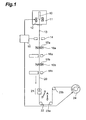
- Fig. 1 is a schematic view showing an example of apparatus for making the coated optical fiber in accordance with the present invention, illustrating a process in which a glass optical fiber drawn from an optical fiber glass preform ends up being wound about a drum.
- This apparatus is equivalent to that disclosed in Japanese Patent Application Laid-Open No. HEI 8-295528.
- 10 refers to an optical fiber glass preform, 11 a drawing furnace, 12 a heater, 13 a glass optical fiber, 14 a laser outer diameter meter, 15 a drawing control section, 16a, 16b coating dies, 17a, 17b coating resin materials, 18a, 18b UV irradiating apparatus, 20 a coated optical fiber, 21 a guide roller, 22 a swinging guide roller, 23a, 23b stationary guide rollers, and 24 a drum.
- the optical fiber glass preform 10 As the optical fiber glass preform 10, those made by various methods such as vapor-phase axial deposition method (VAD method), outside vapor deposition method (OVD method), and modified chemical vapor deposition method (MCVD method) can be used.
- VAD method vapor-phase axial deposition method
- ODD method outside vapor deposition method
- MCVD method modified chemical vapor deposition method
- the optical fiber glass preform 10 comprises a core part 10a to become a core of the glass optical fiber 13, and a cladding part 10b to become a cladding of the glass optical fiber 13.
- the optical fiber glass preform 10 is set within the drawing furnace 11, so that one end of the optical fiber glass preform 10 is heated/softened by the heater 12, whereby the glass optical fiber 13 shown in Fig. 2B is drawn (first step) .
- the drawing rate is 100 m/min, for example, though it can be selected variously.
- a dispersion-shifted fiber having an outside diameter of 125 ⁇ m
- the outer diameter of the drawn glass optical fiber 13 is measured by the laser outer diameter meter 14.
- the result of measurement of the outer diameter of the glass optical fiber 13 is fed back to the drawing control section 15, whereby the heating temperature of the heater 12 and the drawing rate of the glass optical fiber 13 are controlled so as to attain a predetermined outer diameter (usually 125 ⁇ m).
- the glass optical fiber 13 drawn to a predetermined outer diameter is coated with a first layer coating 19a by the first coating die 16a to which the coating resin material 17a having a low Young' s modulus is supplied.
- the first layer coating 19a is formed such that the coating resin material 17a is cured by the first UV irradiating apparatus 18a so as to have a coating outer diameter of about 200 ⁇ m after curing.
- the optical fiber coated with the first layer coating 19a is coated with a second layer coating 19b by the second coating die 16b to which the coating resin material 17b having a high Young's modulus is supplied.
- the second layer coating 19b is formed such that the coating resin material 17b is cured by the second UV irradiating apparatus 18b so as to have a coating outer diameter of about 245 ⁇ m after curing (see Fig. 2C).
- a single coating die may apply the coating resin material 17a having a low Young's modulus onto the glass optical fiber 13, and the coating resin material 17b having a high Young's modulus thereon, and then a UV irradiating apparatus may simultaneously cure both resin materials.
- a UV-curable polyether type urethane acrylate resin is used as a specific example of each of the coating resin materials 17a, 17b.
- the coating resin materials 17a, 17b may also contain a diluent monomer for diluting the urethane acrylate resin.
- the coating resin material 17a may contain a polar monomer (e.g., acrylamide, N-vinyl pyrrolidone, and acryloyl morpholine), a monomer having a heterocycle (e.g., N-vinyl caprolactam), and a monomer having a multi-membered ring (e.g., isobornyl acrylate).
- coated optical fiber 20 subsequently passes the guide roller 21, swinging guide roller 22, and stationary guide rollers 23a and 23b, so as to be taken up by the drum 24.
- the guide roller 21 comprises a roller pair 21a and a roller pair 21b disposed parallel thereto, whereas the coated optical fiber 20 is guided through the gap (about 2 mm) between the pair of rollers 21a and the gap (about 2 mm) between the pair of rollers 21b.
- the swinging guide roller 22 is used for lowering the PMD by alternately twisting the coated optical fiber 20.
- Figs. 3 and 4 are views for explaining how the swinging guide roller 22 twists the coated optical fiber 20.
- Fig. 3 is a view showing the positional relationship between the swinging guide roller 22 and the stationary guide roller 23a as seen from the direction of A in Fig. 1
- Fig. 4 is a view showing the positional relationship between the swinging guide roller 22 and the guide roller 21 as seen from the direction of B in Fig. 1.
- the stationary guide roller 23a in the next stage is placed right beside the swinging guide roller 22, whereas the coated optical fiber 20 comes into contact with the circumferential face of the swinging guide roller 22 by an angle of about 90°, and then moves to the stationary guide roller 23a.
- the stationary guide roller 23a is formed with a V-shaped narrow groove 25 so as to prevent the coated optical fiber 20 from rotating on the surface of the roller 23a. Since the coated optical fiber 20 is kept from rotating on the surface of the stationary guide roller 23a, the coated optical fiber 20 can be twisted with a high efficiency with respect to the pivoting of the swinging guide roller 22.
- the guide roller 21 in the stage upstream the swinging guide roller 22 is constituted by pair rollers 21a and 21b, which are placed directly above the swinging guide roller 22.
- Each pair of rollers 21a and 21b are disposed parallel to each other with a predetermined gap t therebetween
- the coated optical fiber 20 rotates on the surface of the swinging guide roller 22 as in the case of Fig. 3, whereas the part of coated optical fiber 20 located at the guide roller 21 in front of the guide roller 21 is also displaced to swinging directions of the swinging guide roller 22.
- the coated optical fiber 20 attains a predetermined displacement or greater, the coated optical fiber 20 comes into contact with one half of the guide roller 21, thereby suppressing the displacement.
- the displacement is suppressed as such, the reduction in the amount of twisting applied to the coated optical fiber 20 and the thickness deviation in the first layer coating 19a and second layer coating 19b can effectively be restrained from occurring.
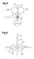
- Fig. 5 is a front view showing a guide roller of a type different from that of the swinging guide roller of Figs. 3 and 4, and a stationary guide roller
- Fig. 6 is a side view showing the swinging guide roller and stationary guide roller as seen from the direction of B in Fig. 5.
- the coated optical fiber 20 is held by a stationary guide roller 31 constituted by two stationary guide rollers 31a, 31b, and travels downward through a predetermined traveling line.
- a swinging guide roller 32 constituted by two swinging guide rollers 32a, 32b is disposed below the stationary guide roller 31.
- the coated optical fiber 20 is held between the swinging guide rollers 32a, 32b, so as to travel downward.
- a guide roller (not depicted) is disposed below the swinging guide roller 32, so as to change the traveling direction of the coated optical fiber 20 as appropriate, such that the fiber is taken up by a drum.
- Each constituent of the swinging guide roller 32 is secured by a securing member 33 so as to be pivotable about the axis y shown in Fig. 5. Also, the securing member 33 is pivotable about the x axis shown in Fig. 6. As a consequence, the swinging roller 32 is pivotable together with the securing member 33 about the axis x shown in Fig. 6.
- the two swinging guide rollers 32a, 32b are pivoted in synchronization with each other such that, when one of them rotates by + ⁇ about the axis x, the other rotates by - ⁇ .
- the swinging guide rollers 32a, 32b holding the coated optical fiber 20 therebetween are pivoted about the axis x as such, the coated optical fiber 20 is twisted.
- the coated optical fiber 20 can be alternatively twisted clockwise and counterclockwise with respect to the moving direction thereof.
- the first layer coating 19a can be prevented from breaking and generating voids if the first layer coating 19a has a breaking strength of at least 4.0 MPa or a Young's modulus of at least 0.4 MPa.
- the present invention is a method of making an optical fiber by twisting the coated optical fiber 20 and reducing its polarization mode dispersion (PMD), and takes account of the fact that the PMD value relates to the radius R of swinging guide roller 22, 32 and the tension T of glass optical fiber at the time of drawing.
- PMD polarization mode dispersion
- the transmission loss of an optical fiber can be made smaller as the tension at the time of drawing the optical fiber is greater. Since it is desirable that the transmission loss be 0.3 dB/km or less at a wavelength of 1.55 ⁇ m in practice, the drawing tension T is set to at least 2.2 (N/fiber), preferably 2.7 (N/fiber), in order to attain the above-mentioned transmission loss stably. However, since there will be a possibility of breaking the optical fiber if the tension T is too strong, it is necessary that the optical fiber be drawn at a tension taking account of coating conditions of the optical fiber and the like. Therefore, it is preferred that the drawing tension T be 5.0 (N/fiber) or less. The drawing tension T is indicated by the force applied to an optical fiber, and is expressed by (N/fiber).
- the T/R is set to 28 to 100 when making the coated optical fiber 26. If the T/R is less than 28, the coated optical fiber will slide on the swinging guide roller, or the swinging guide roller itself will become greater and there by deteriorating space efficiency; whereas the PMD value will increase if the T/R exceeds 100.
- the number of swinging movements of swinging guide roller 22, 32 is set to 0.33 to 3.33 (s -1 ) when making the coated optical fiber 26. If the number of swinging movements is less than 0.33 (s -1 ), the coated optical fiber 20 cannot be twisted sufficiently, whereby the PMD value cannot be reduced. If the number of swinging movements exceeds 3.33 (s -1 ), on the other hand, the swinging guide roller 22 may move so fast that the coating of the coated optical fiber 20 will slide on the swinging guide roller 22, whereby the coated optical fiber 20 will twist insufficiently, thus failing to decrease the PMD as well.
- the Young's modulus of the first layer coating 19a is desirably set to 0.2 to 0. 7 (MPa), more desirably 0.4 to 0.7 MPa.
- the breaking strength of the first layer coating 19a may decrease so that voids will be likely to occur within the coating due to squeezing upon the pivoting of swinging guide roller 22, 32; whereas it will tend to be difficult to reduce loss increase by lateral pressure and remove the coating if the Young's modulus exceeds 0.7 MPa.
- the breaking strength of the first layer coating 19a be set to at least 4.0 (MPa) when coating the glass optical fiber 13 with the first layer coating 19a. In this case, no voids occur within the first layer coating 19a.
- the Young's modulus of the second layer coating 19b is preferably set to 150 to 1500 (MPa) when coating the glass optical fiber 13 with the second layer coating 19b.
- the second layer coating 19b has a Young's modulus of less than 150 MPa, it will tend to be damaged externally with dust (minute foreign matters) and break upon high-tension screening. If the Young' s modulus of the second layer coating 19b exceeds 1500 MPa, on the other hand, it will tend to become difficult to remove the coating.
- the Young's moduli of the first layer coating 19a and second layer coating 19b can be adjusted by the molecular weight of polyether part and the kind of diluent monomer. Namely, Young's moduli of the first layer coating 19a and second layer coating 19b can be decreased if the molecular weight of the polyether part is made greater and if a linear monofunctional diluent monomer having a large molucular weight is chosen.
- the Young's moduli and breaking strengths of the first layer coating 19a and second layer coating 19b can be increased if the molecular weight is lowered so as to enhance the rigidity of the urethane part.
- the Young's moduli and breaking strengths can be raised if the compounding amount of the multifunctional monomer is increased and if a monomer having a high rigidity is chosen.
- the coating resin material 17a contains an oligomer having a molecular weight of at least 5000, a multifunctional monomer having a methylene group with a carbon number of 5 to 11, and a monomer having a heterocycle and/or a monomer having a multi-membered ring, whereas the multifunctional monomer has a weight ratio of 0.02 to 0.04 with respect to the oligomer.
- the oligomer has a molecular weight of less than 5000, the Young's modulus of first layer coating will tend to increase.
- the molecular weight of the oligomer is 30,000 or less. If the molecular weight exceeds 30,000, the viscosity of the resulting composition will tend to become too high, whereby it will be harder to handle.
- An example of the oligomers is polyether diol.
- the Young's modulus of the first layer coating will tend to become too high, whereby it will be harder to reduce the loss increase by lateral pressure and remove the coating. If the carbon number of the methylene group exceeds 11, on the other hand, the breaking strength of the first layer coating will tend to decrease, whereby voids will be likely to occur within the first layer coating.
- An example of the multifunctional monomer is nonanediol diacrylate.
- heterocycle lactam
- monomer having a heterocycle is N-vinyl caprolactam
- An example of the monomer having a multi-membered ring is isobornyl acrylate.
- the breaking strength of the first layer coating will tend to decrease, whereby voids will be likely to occur within the first layer coating. If it exceeds 0.04, on the other hand, the Young's modulus of the first layer coating will tend to become too high, whereby it will be harder to reduce the loss increase by lateral pressure and remove the coating.
- the coating resin material 17a may further contain an aliphatic monomer.
- the first layer coating 19a has an adhesion force of 0.5 to 2.0 (N/cm) with respect to glass.
- the adhesion force is less than 0.5 (N/cm), it will be too small, whereby the first layer coating 19a will tend to peel off from the glass optical fiber 13 if the force for pressing the coated optical fiber 20 against the swinging guide roller 22, 32 increases. If the adhesion force exceeds 2.0 (N/cm), on the other hand, the adhesion force will become too large, whereby the coating removal characteristic will tend to deteriorate.
- the adhesion force between the first layer coating 19a and glass can be adjusted by the amount of the polar monomer (e.g., acrylamide, N-vinyl pyrrolidone, and acryloyl morpholine), monomer having a heterocycle, and/or monomer having a multi-membered ring used in the coating resin material 17a.
- the adhesion force can also be adjusted by a silane coupling agent.
- the coating of the coated optical fiber is formed by two layers, i.e., the first layer coating 19a and second layer coating 19b, as explained in Fig. 1.
- the first layer coating 19a is formed from a soft material provided with a cushioning effect
- the second layer coating 19b is formed from a hard material resistant to abrasions.
- physical values concerning the coating of the coated optical fiber were measured as follows :
- Young's modulus becomes lower in the resin applied to the optical fiber than that measured when the coating material is in a film form. This is because of the fact that the coating attains a high temperature due to the radiant heat and the heat caused by the curing reaction within the UV irradiating apparatus used in the optical fiber drawing apparatus, whereby chain transfer reactions and termination reactions become predominant, thus keeping crosslinking reactions from advancing.
- the Young's modulus of the first layer coating of the coated optical fiber the value in the state applied to the coated optical fiber is important.
- the Young's modulus of the first layer coating was directly calculated by using Push-in-modulus method (see literature: 43rd IWCS [1994] p. 552).
- the specific measuring method is as follows: First, a bundle of coated optical fibers were held in an acrylic pipe, the gap between the pipe and each coated optical fiber was filled with an epoxy resin, which was then cured, and thus obtained assembly was sliced with a cutter, whereby a disc-shaped sample having a predetermined thickness was prepared. Thereafter, using a microhardness tester, the glass part of the sliced disc-shaped sample was pressed with an indenter. From the amount of displacement of glass and indentation force at that time, the Young's modulus of the first layer coating was calculated. Though the second layer coating is integrally included in the coating, the second layer coating can substantially be neglected since the Young's modulus of the second layer coating is greater than that of the first layer coating by at least two digits.
- the second layer coating was calculated as follows: First, the coated optical fiber was cut into a length of several tens of centimeters, thus cut optical fiber was immersed in acetone so that the coating swelled, and the pipe-shaped coating was collected. After thus collected pipe-shaped coating was dried, its state was adjusted for at least 24 hours at a temperature of 23°C ⁇ 2°C and a relative humidity of 50 ⁇ 5%, then its tensile strength at the time of 2.5% extension was measured at a gauge distance of 25 mm and a pulling rate of 1 mm/min, and thus measured value was taken as the Young's modulus of the second layer coating.
- the other features were in conformance with JIS K7127. Though thus collected coating is one in which the first and second layer coatings are integrated with each other, the first layer coating can substantially be neglected since the Young's modulus of the second layer coating is greater than that of the first layer coating by at least two digits.
- the adhesion force between glass and the first layer coating relating to peeling of coating and the coating removal characteristic were calculated by preparing a test sheet in the following procedure:
- the breaking strength of the first layer coating relating to the occurrence of voids in the first layer coating caused by the swinging operation for twisting the coated optical fiber was calculated by the following procedure:
- samples No. 1 to No. 22 of coated optical fibers were made by the making apparatus shown in Fig. 1 using the swinging guide roller 22 (see Figs. 3 and 4).
- the results of evaluation of thus obtained samples No. 1 to No. 22 of coated optical fibers are shown in the following.
- the evaluated items were PMD values, whether or not they broke during drawing, loss characteristics by lateral pressure, coating removal characteristics, occurrence of voids in the coating, and occurrence of peeling in the coating.
- the drawing rate was 100 m/min.
- optical fibers can reduce their transmission loss when drawn at a high tension, they will break if the tension is too high. Therefore, as for glass optical fibers before forming coatings, whether they break or not upon drawing were investigated while varying the tension.
- the PMD value was favorable when T/Rwas 100 or less according to samples No. 2 to No. 5 (Examples 1 to 4), but deteriorated in sample No. 1 (Comparative Example 1) in which T/R was 120.
- the PMD value was presumed to have deteriorated because of the fact that the pressing force of the swinging guide roller against the coated optical fiber became so high that the coating was collapsed, which increased the rotating resistance, thereby making the amount of twisting of the optical fiber insufficient.
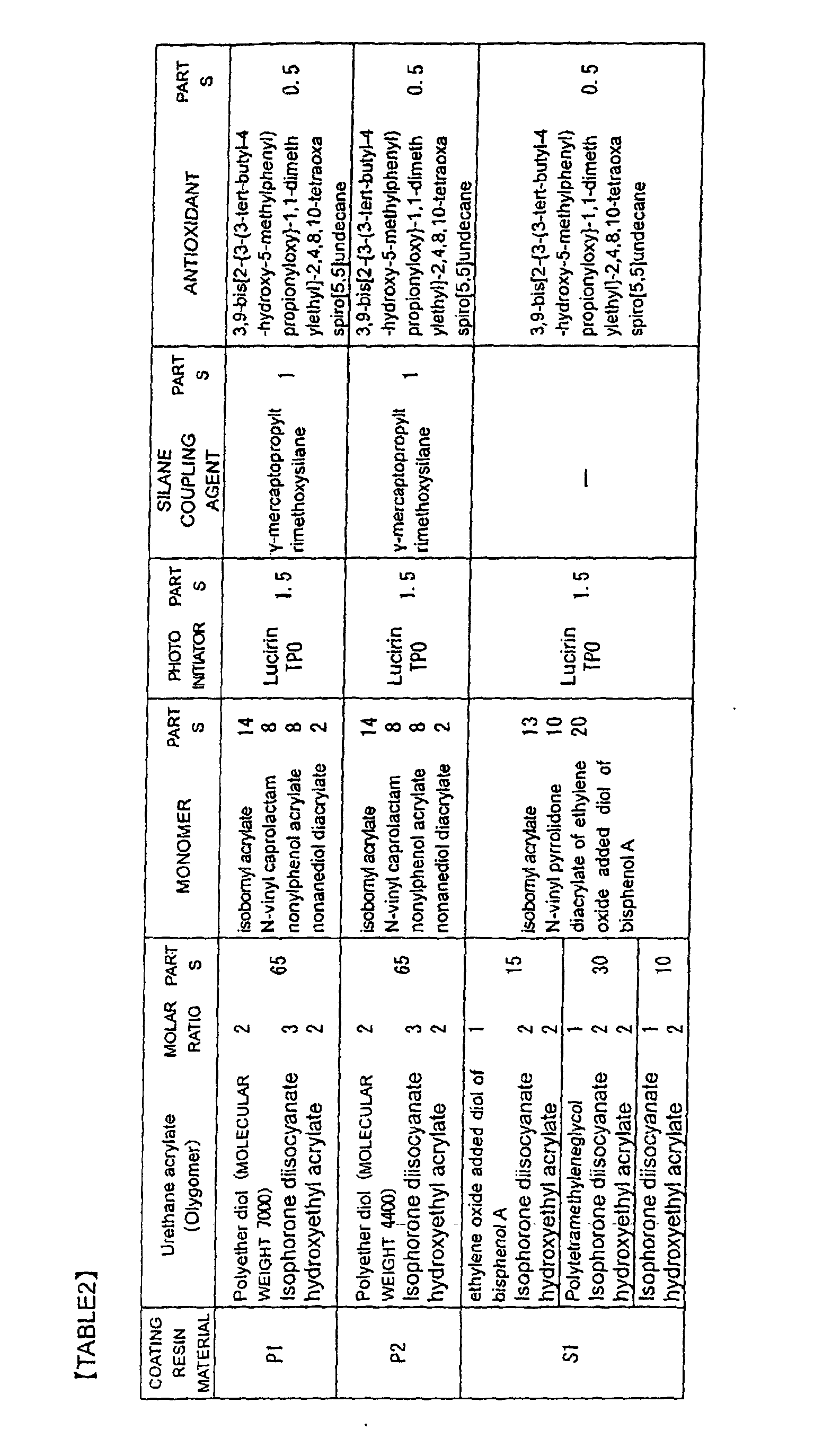
- the coating resin material of the first layer coating in samples No. 10 to No. 14 was one in which the ratio of the monofunctional monomer to the oligomer was decreased in the composition of P1 shown in Table 2, whereby the Young's modulus of the first layer coating was adjusted.
- the coating resin material of the second layer coating in samples No. 10 to No. 15 was one in which the ratio of the monofunctional monomer to the oligomer was increased/decreased in the composition of S1 shown in Table 2, whereby the Young's modulus of the second layer coating was increased/decreased.
- the tension T at the time of drawing the glass optical fiber was 4.0 (N/fiber)
- the swinging guide roller radius R was 0.08 (m)
- T/R was 50, so that they were held constant.
- the number of swinging movements was 0.83 s -1 .
- Optical fibers increase their transmission loss upon receiving lateral pressures and abrasions, which is greatly influenced by coating materials thereof.
- a sandpaper sheet of JIS #1000 was wound about a bobbin having a barrel diameter of about 280 mm, the transmission loss yielded when the coated optical fiber was wound thereon by a length of 600 m at a tension of 0.98 (N/fiber) was defined as L1, the transmission yielded when the coated optical fiber was in the state of a bundle of 1000 m (not wound about the bobbin, the lateral pressure being assumed to be zero in this state) was defined as L2, and (L1 - L2) was defined as the loss increase by lateral pressure.
- Cases yielding a loss increase by lateral pressure of 1 (dB/km) or less was evaluated as “favorable” and indicated by “ ⁇ ” in Table 3. Cases yielding a loss increase by lateral pressure exceeding 1 (dB/km) were indicated by " ⁇ ".
- the transmission losses L1, L2 were measured by OTDR at a wavelength of 1.55 ⁇ m.
- the coating of a coated optical fiber has an important role of preventing external damages from occurring due to foreign matters. Coatings susceptible to external damages make it easier for glass to be damaged, thereby increasing the frequency of breaking at screening. Therefore, a high tensile tension was applied to the coated optical fiber after the making thereof, so as to break inferior parts having a low strength. The tension at that time was 21.6 (N/fiber). Cases yielding a screening fiber break frequency of 5 times/1000 km or less was evaluated as “favorable" and indicated by " ⁇ " in Table 3. Cases yielding a screening break frequency exceeding 5 times/1000 km were indicated by " ⁇ " in Table 3.
- the molecular weight of oligomer was preferably at least 5000 from the viewpoint of softening the first layer coating.
Landscapes
- Chemical & Material Sciences (AREA)
- Life Sciences & Earth Sciences (AREA)
- Engineering & Computer Science (AREA)
- Geochemistry & Mineralogy (AREA)
- General Life Sciences & Earth Sciences (AREA)
- Materials Engineering (AREA)
- Organic Chemistry (AREA)
- Physics & Mathematics (AREA)
- Manufacturing & Machinery (AREA)
- Chemical Kinetics & Catalysis (AREA)
- General Chemical & Material Sciences (AREA)
- Optics & Photonics (AREA)
- General Physics & Mathematics (AREA)
- Surface Treatment Of Glass Fibres Or Filaments (AREA)
- Optical Fibers, Optical Fiber Cores, And Optical Fiber Bundles (AREA)
Abstract
Description


Claims (8)
- A method of making a coated optical fiber comprising:wherein said glass optical fiber has a tension T of at least 2.2 (N/fiber) in said first step; anda first step of obtaining a glass optical fiber by drawing an optical fiber glass preform;a second step of forming said glass optical fiber with two layers of coating; anda third step of applying a twist to said glass optical fiber by using a swinging guide roller;
wherein T/R is 28 to 100, where R (m) is the barrel radius of said swinging guide roller, and the number of swinging movements of said swinging guide roller is 0.33 to 3.33 (s-1) in said third step. - A method of making a coated optical fiber according to claim 1, wherein said glass optical fiber has a tension T of 5.0 (N/fiber) or less in said first step.
- A method of making a coated optical fiber according to claim 1, wherein, in said second step, said glass optical fiber is coated with a first layer coating such that said first layer coating has a Young's modulus of 0.2 to 0.7 (MPa).
- A method of making a coated optical fiber according to claim 1, wherein, in said second step, a second layer coating is coated on said first layer coating such that said second layer coating has a Young's modulus of 150 to 1500 (MPa).
- A method of making a coated optical fiber according to claim 1, wherein, in said second step, a first layer coating having a breaking strength of at least 4.0 (MPa) is formed on said glass optical fiber.
- A method of making a coated optical fiber according to claim 1, wherein, in said second step, a first layer coating having an adhesion force of 0.5 to 2.0 (N/cm) with respect to glass is formed on said glass optical fiber.
- A method of making a coated optical fiber according to claim 1, wherein, in said second step,
said glass optical fiber is formed with a first layer coating by using a coating resin material containing:an oligomer having a molecular weight of at least 5000,a multifunctional monomer having a methylene group with a carbon number of 5 to 11, anda monomer having a heterocycle and/or a monomer having a multi-membered ring,said multifunctional monomer having a weight ratio of 0.02 to 0.04 with respect to said oligomer. - A coated optical fiber made by the method of making a coated optical fiber according to one of claims 1 to 7.
Applications Claiming Priority (3)
| Application Number | Priority Date | Filing Date | Title |
|---|---|---|---|
| JP2000389746 | 2000-12-22 | ||
| JP2000389746 | 2000-12-22 | ||
| PCT/JP2001/011394 WO2002051763A1 (en) | 2000-12-22 | 2001-12-25 | Coated optical fiber and production method therefor |
Publications (2)
| Publication Number | Publication Date |
|---|---|
| EP1346959A1 true EP1346959A1 (en) | 2003-09-24 |
| EP1346959A4 EP1346959A4 (en) | 2005-04-06 |
Family
ID=18856235
Family Applications (1)
| Application Number | Title | Priority Date | Filing Date |
|---|---|---|---|
| EP01272317A Withdrawn EP1346959A4 (en) | 2000-12-22 | 2001-12-25 | SOLDERED OPTIC FIBER AND METHOD FOR PRODUCING SAME |
Country Status (4)
| Country | Link |
|---|---|
| US (1) | US20030051511A1 (en) |
| EP (1) | EP1346959A4 (en) |
| JP (1) | JP4134723B2 (en) |
| WO (1) | WO2002051763A1 (en) |
Cited By (1)
| Publication number | Priority date | Publication date | Assignee | Title |
|---|---|---|---|---|
| EP1362835B1 (en) * | 2001-02-20 | 2017-04-05 | Sumitomo Electric Industries, Ltd. | Coated optical fiber, optical fiber tape core using it and optical fiber unit |
Families Citing this family (10)
| Publication number | Priority date | Publication date | Assignee | Title |
|---|---|---|---|---|
| JP2005320191A (en) * | 2004-05-07 | 2005-11-17 | Fujikura Ltd | Optical fiber manufacturing method and optical fiber manufacturing apparatus |
| KR100886753B1 (en) * | 2007-07-18 | 2009-03-04 | 연세대학교 산학협력단 | Manufacturing method of optical fiber yarn for water-resistant luminescence |
| CN101533122B (en) * | 2009-04-27 | 2010-08-04 | 中天科技光纤有限公司 | Preparation method of single-mode optical fiber for high-strength large-disc long submarine cable |
| KR101090332B1 (en) * | 2009-09-02 | 2011-12-07 | 주식회사 엘티전자 | Lighting fixture using fiber optic fabric and manufacturing method thereof |
| CN102686529B (en) * | 2010-06-11 | 2014-10-22 | 株式会社藤仓 | Method and device for manufacturing fiber-optic strands |
| WO2016088801A1 (en) * | 2014-12-03 | 2016-06-09 | 住友電気工業株式会社 | Optical fiber core and optical fiber tape core |
| US11117826B2 (en) * | 2017-07-25 | 2021-09-14 | Made In Space, Inc. | System and method for manufacturing optical fiber |
| JP7266789B2 (en) * | 2018-02-20 | 2023-05-01 | 住友電気工業株式会社 | Optical fiber manufacturing method and optical fiber |
| EP4054988B1 (en) * | 2019-11-04 | 2026-08-12 | Corning Incorporated | Fiber coatings with low pullout force |
| JP7898262B2 (en) * | 2021-07-02 | 2026-07-31 | 住友電気工業株式会社 | Optical fiber manufacturing method |
Family Cites Families (9)
| Publication number | Priority date | Publication date | Assignee | Title |
|---|---|---|---|---|
| US4962992A (en) * | 1989-05-15 | 1990-10-16 | At&T Bell Laboratories | Optical transmission media and methods of making same |
| US5298047A (en) * | 1992-08-03 | 1994-03-29 | At&T Bell Laboratories | Method of making a fiber having low polarization mode dispersion due to a permanent spin |
| US5381504A (en) * | 1993-11-15 | 1995-01-10 | Minnesota Mining And Manufacturing Company | Optical fiber element having a permanent protective coating with a Shore D hardness value of 65 or more |
| JP3557606B2 (en) * | 1995-03-01 | 2004-08-25 | 住友電気工業株式会社 | Optical fiber and method of manufacturing optical fiber |
| US6076376A (en) * | 1995-03-01 | 2000-06-20 | Sumitomo Electric Industries, Ltd. | Method of making an optical fiber having an imparted twist |
| CN1113043C (en) * | 1995-08-16 | 2003-07-02 | 等离子光纤维股份有限公司 | Optical Fiber with Low Polarization Mode Dispersion |
| EP1116701B1 (en) * | 1998-09-24 | 2011-11-09 | Sumitomo Electric Industries, Ltd. | Method for producing optical fiber |
| US6427044B1 (en) * | 1999-06-23 | 2002-07-30 | Sumitomo Electric Industries, Ltd. | Optical fiber |
| US7067564B2 (en) * | 2000-11-22 | 2006-06-27 | Dsm Ip Assets B.V. | Coated optical fibers |
-
2001
- 2001-12-25 EP EP01272317A patent/EP1346959A4/en not_active Withdrawn
- 2001-12-25 JP JP2002552868A patent/JP4134723B2/en not_active Expired - Fee Related
- 2001-12-25 US US10/204,477 patent/US20030051511A1/en not_active Abandoned
- 2001-12-25 WO PCT/JP2001/011394 patent/WO2002051763A1/en not_active Ceased
Cited By (1)
| Publication number | Priority date | Publication date | Assignee | Title |
|---|---|---|---|---|
| EP1362835B1 (en) * | 2001-02-20 | 2017-04-05 | Sumitomo Electric Industries, Ltd. | Coated optical fiber, optical fiber tape core using it and optical fiber unit |
Also Published As
| Publication number | Publication date |
|---|---|
| JPWO2002051763A1 (en) | 2004-04-22 |
| WO2002051763A1 (en) | 2002-07-04 |
| JP4134723B2 (en) | 2008-08-20 |
| EP1346959A4 (en) | 2005-04-06 |
| US20030051511A1 (en) | 2003-03-20 |
Similar Documents
| Publication | Publication Date | Title |
|---|---|---|
| JP4134724B2 (en) | Coated optical fiber, optical fiber ribbon and optical fiber unit using the same | |
| CN112400127B (en) | Small diameter low attenuation optical fiber | |
| EP0582405B1 (en) | Method of drawing an optical fibre and fibre produced thereby | |
| EP0729919B1 (en) | Optical fiber and method of manufacturing the same | |
| CN112424658A (en) | Low attenuation optical fiber with small outer diameter | |
| CN114930218B (en) | Radius reduced optical fiber with high mechanical reliability | |
| CN111650686A (en) | Low diameter optical fiber | |
| US20030051511A1 (en) | Coated optical fiber and production method therefor | |
| AU777514B2 (en) | Coated optical fiber | |
| US8033141B2 (en) | Method of manufacturing optical fiber | |
| CN118159887A (en) | optical fiber | |
| CN115190871A (en) | Reduced coating diameter chlorine doped silica optical fiber with low loss and microbending sensitivity | |
| EP0856759B1 (en) | Method of making optical fiber ribbon | |
| NZ509043A (en) | Method and apparatus for twisting a coated optical fiber during drawing from a preform | |
| US4874415A (en) | Method of manufacturing a high mechanical strength optical fiber by drawing under high tension | |
| EP1258751A1 (en) | Optical fiber, method for manufacturing same, and optical transmission system comprising the same | |
| JPH09202640A (en) | Method and apparatus for reducing coating deformation of coated optical fibers during the fiber drawing process | |
| JP2008026903A (en) | Optical fiber with extended bandwidth for crimp and cleave connector | |
| JP2004175611A (en) | Method and apparatus for manufacturing optical fiber | |
| JP3518089B2 (en) | Broadband optical fiber, its core, cord, and optical fiber with connector, cord | |
| JP2001083381A (en) | Coated optical fiber | |
| JP4194976B2 (en) | Manufacturing method of optical fiber | |
| CN116209929A (en) | Single mode optical fiber with thin coating for high density optical fiber cables and interconnects | |
| JP2002333555A (en) | Optical fiber, optical fiber coil, optical fiber coil unit, optical fiber transmission line, and method for manufacturing optical fiber | |
| JP2004277271A (en) | Method and apparatus for manufacturing optical fiber |
Legal Events
| Date | Code | Title | Description |
|---|---|---|---|
| PUAI | Public reference made under article 153(3) epc to a published international application that has entered the european phase |
Free format text: ORIGINAL CODE: 0009012 |
|
| 17P | Request for examination filed |
Effective date: 20020815 |
|
| AK | Designated contracting states |
Kind code of ref document: A1 Designated state(s): AT BE CH CY DE DK ES FI FR GB GR IE IT LI LU MC NL PT SE TR |
|
| RBV | Designated contracting states (corrected) |
Designated state(s): AT BE CH FR GB IT LI |
|
| REG | Reference to a national code |
Ref country code: DE Ref legal event code: 8566 |
|
| A4 | Supplementary search report drawn up and despatched |
Effective date: 20050222 |
|
| 17Q | First examination report despatched |
Effective date: 20060803 |
|
| STAA | Information on the status of an ep patent application or granted ep patent |
Free format text: STATUS: THE APPLICATION IS DEEMED TO BE WITHDRAWN |
|
| 18D | Application deemed to be withdrawn |
Effective date: 20061214 |