CN116209929A - Single mode optical fiber with thin coating for high density optical fiber cables and interconnects - Google Patents
Single mode optical fiber with thin coating for high density optical fiber cables and interconnects Download PDFInfo
- Publication number
- CN116209929A CN116209929A CN202180064295.7A CN202180064295A CN116209929A CN 116209929 A CN116209929 A CN 116209929A CN 202180064295 A CN202180064295 A CN 202180064295A CN 116209929 A CN116209929 A CN 116209929A
- Authority
- CN
- China
- Prior art keywords
- coating
- optical fiber
- modulus
- microns
- high modulus
- Prior art date
- Legal status (The legal status is an assumption and is not a legal conclusion. Google has not performed a legal analysis and makes no representation as to the accuracy of the status listed.)
- Pending
Links
Images


Classifications
-
- G—PHYSICS
- G02—OPTICS
- G02B—OPTICAL ELEMENTS, SYSTEMS OR APPARATUS
- G02B6/00—Light guides; Structural details of arrangements comprising light guides and other optical elements, e.g. couplings
- G02B6/02—Optical fibres with cladding with or without a coating
- G02B6/036—Optical fibres with cladding with or without a coating core or cladding comprising multiple layers
- G02B6/03616—Optical fibres characterised both by the number of different refractive index layers around the central core segment, i.e. around the innermost high index core layer, and their relative refractive index difference
- G02B6/03638—Optical fibres characterised both by the number of different refractive index layers around the central core segment, i.e. around the innermost high index core layer, and their relative refractive index difference having 3 layers only
- G02B6/0365—Optical fibres characterised both by the number of different refractive index layers around the central core segment, i.e. around the innermost high index core layer, and their relative refractive index difference having 3 layers only arranged - - +
-
- G—PHYSICS
- G02—OPTICS
- G02B—OPTICAL ELEMENTS, SYSTEMS OR APPARATUS
- G02B6/00—Light guides; Structural details of arrangements comprising light guides and other optical elements, e.g. couplings
- G02B6/02—Optical fibres with cladding with or without a coating
- G02B6/02004—Optical fibres with cladding with or without a coating characterised by the core effective area or mode field radius
- G02B6/02009—Large effective area or mode field radius, e.g. to reduce nonlinear effects in single mode fibres
- G02B6/02014—Effective area greater than 60 square microns in the C band, i.e. 1530-1565 nm
-
- G—PHYSICS
- G02—OPTICS
- G02B—OPTICAL ELEMENTS, SYSTEMS OR APPARATUS
- G02B6/00—Light guides; Structural details of arrangements comprising light guides and other optical elements, e.g. couplings
- G02B6/02—Optical fibres with cladding with or without a coating
- G02B6/02004—Optical fibres with cladding with or without a coating characterised by the core effective area or mode field radius
- G02B6/02009—Large effective area or mode field radius, e.g. to reduce nonlinear effects in single mode fibres
-
- G—PHYSICS
- G02—OPTICS
- G02B—OPTICAL ELEMENTS, SYSTEMS OR APPARATUS
- G02B6/00—Light guides; Structural details of arrangements comprising light guides and other optical elements, e.g. couplings
- G02B6/02—Optical fibres with cladding with or without a coating
- G02B6/02395—Glass optical fibre with a protective coating, e.g. two layer polymer coating deposited directly on a silica cladding surface during fibre manufacture
-
- G—PHYSICS
- G02—OPTICS
- G02B—OPTICAL ELEMENTS, SYSTEMS OR APPARATUS
- G02B6/00—Light guides; Structural details of arrangements comprising light guides and other optical elements, e.g. couplings
- G02B6/44—Mechanical structures for providing tensile strength and external protection for fibres, e.g. optical transmission cables
- G02B6/4401—Optical cables
- G02B6/4403—Optical cables with ribbon structure
Abstract
The provided optical fiber comprises: a core region having a cladding region with a radius of less than about 62.5 microns; a polymeric coating comprising a high modulus layer and a low modulus layer, wherein the low modulus inner coating has a thickness in the range of 4 microns to 20 microns, the low modulus inner coating has a modulus of less than or equal to about 0.35MPa, the high modulus coating has a thickness in the range of 4 microns to 20 microns, the high modulus inner coating has a modulus of greater than or equal to about 1.6GPa, and wherein the optical fiber has a puncture resistance of greater than 20g, and wherein the optical fiber has a microbending attenuation penalty of less than 0.03dB/km, and wherein the coated optical fiber has an outer diameter of less than or equal to 175 microns.
Description
Cross reference to related applications
The present application claims priority from U.S. provisional application serial No. 63/054,563, filed on 7/21/2020, in accordance with 35 u.s.c. ≡119, the contents of which are hereby incorporated by reference in their entirety.
Technical Field
The present disclosure pertains to single mode optical fibers. More specifically, the present disclosure pertains to small diameter single mode optical fibers. Most particularly, the present disclosure pertains to small diameter single mode optical fibers having reduced coating thickness without significantly reducing puncture resistance.
Background
Optical fiber technology is penetrating into data centers due to the high bandwidth, low latency, low power consumption, and immune EMI/RFI required for cloud computing and internet of things. Future ultra-large scale data centers require special functions, such as 100K servers distributed over 50 ten thousand square feet, thus creating a need for increased capacity, flexibility, and efficiency in interconnection schemes within the data center. Thus, a large number of interconnects are required within the data center. Ribbon cables allow for higher fiber counts; however, these higher fiber counts may require smaller diameter fibers for installation into the ribbon cable. For example, replacing a 250 μm overall diameter double layer acrylate coated fiber optic ribbon cable with a 125 μm overall diameter bare fiber optic ribbon cable results in a volume reduction of at least 75%. Processing the bare fiber into a ribbon cable then results in fiber breakage.
In addition, undersea fiber optic cables are designed to carry telecommunications signals across land, ocean, and sea. Telecommunication signals on undersea fiber optic cables have increased dramatically over the past several years, with over 90% of intercontinental communication signals currently being carried on these cables. Thus, the demand for such undersea optical cable transmission capacity has increased as driven by the growing internet communications between different continents. Traditionally, this capacity increase is driven by, for example: the bandwidth capacity per fiber is increased but the bit rate is increased or Dense Wavelength Division Multiplexing (DWDM) is used while keeping the number of fibers small (typically between 4 and 8 fiber pairs).
However, implementing these advanced transmission techniques has caused the power consumption of the optical repeater in such systems to exceed the level that the terminal can supply. This power limitation forces undersea system designers to use higher fiber counts that would require smaller diameter fibers to accommodate the limited space inside the optical repeater. Preferably, the cladding diameter of these fibers needs to be maintained at 125 microns to facilitate fusion splicing with conventional single mode fibers, which means that smaller diameters are achieved by reducing the thickness of the protective coating. Such thinner coatings need to have a high modulus in combination with a sufficiently large cross-sectional area to ensure high resistance to puncture and abrasion.
Improvements to the foregoing are desirable. Accordingly, the inventors developed thin-coated single-mode optical fibers with sufficiently high mechanical reliability.
Disclosure of Invention
According to embodiment 1 of the present disclosure, the present specification extends to an optical fiber having: a core region; a cladding region surrounding the core region, the cladding region comprising: an inner cladding layer immediately adjacent the core region, and an outer cladding layer surrounding the inner cladding layer, wherein the radius of the cladding region is less than about 62.6 microns; and a polymer coating comprising a high modulus coating layer surrounding the cladding region and a low modulus coating layer disposed between the cladding region and the high modulus coating layer, wherein the low modulus coating layer The thickness of the inner layer of material is in the range of 4 micrometers to 20 micrometers, the modulus of the inner layer of low modulus coating is less than or equal to about 0.35MPa, the thickness of the layer of high modulus coating is in the range of 4 micrometers to 20 micrometers, the modulus of the inner layer of high modulus coating is greater than or equal to about 1.6GPa, and wherein the puncture resistance of the optical fiber is greater than 20g, and wherein the microbending attenuation penalty of the optical fiber is less than 0.03dB/km, and wherein the outer diameter of the coated optical fiber is less than or equal to 175 micrometers, wherein the puncture resistance of the optical fiber is calculated by the equation: p (P) R =P 0 +C 1 E s A s Wherein A is S Is the cross-sectional area of the high modulus coating, wherein E S Is the elastic modulus of the high modulus coating, wherein P 0 Is a coefficient of value 11.3g and C 1 Is a value of 2.1g/MPa/mm 2 Wherein the microbending attenuation penalty of the fiber is calculated by the following equation: wherein f 0 Is the average transverse pressure of the outer surface in contact with the high modulus coating, wherein σ is the standard deviation of the roughness of the outer surface in contact with the high modulus coating, wherein +.>
 And wherein->
 And wherein->
 And wherein the first and second heat exchangers are configured to,
 wherein R is g Is the radius of the glass, R s Is the outer radius, t, of the high modulus overcoat p Is the thickness of the low modulus inner coating, t s Is the thickness of the high modulus overcoat, E g Is the elastic modulus of glass, E p Is the elastic modulus of the low modulus inner coating and E S Is a high modulus coatingModulus of elasticity.
According to embodiment 2 of the present disclosure, the optical fiber of embodiment 1, wherein the microbending attenuation penalty of the optical fiber is less than or equal to 0.01dB/km.
According to embodiment 3 of the present disclosure, the optical fiber of embodiment 1, wherein the microbending attenuation penalty of the optical fiber is less than or equal to 0.007dB/km.
According to embodiment 4 of the present disclosure, the optical fiber of embodiment 1, wherein the microbending attenuation penalty of the optical fiber is less than or equal to 0.003dB/km.
According to embodiment 5 of the present disclosure, the optical fiber of embodiment 1, wherein the puncture resistance of the optical fiber is not less than 25g.
According to embodiment 6 of the present disclosure, the optical fiber of embodiment 1, wherein the puncture resistance of the optical fiber is not less than 30g.
According to embodiment 7 of the present disclosure, the optical fiber of embodiment 1, wherein the radius of the cladding region is less than 52.5 microns and the puncture resistance of the optical fiber is greater than 40g.
According to embodiment 8 of the present disclosure, the optical fiber of embodiment 1, wherein the high modulus coating layer has a thickness of 9 micrometers to 18 micrometers.
According to embodiment 9 of the present disclosure, the optical fiber of embodiment 1, wherein the attenuation of the optical fiber is less than 0.20dB/km.
According to embodiment 10 of the present disclosure, the optical fiber of embodiment 1, wherein the mode field diameter of the optical fiber at 1310nm is not less than 8.6.
According to embodiment 11 of the present disclosure, the present specification extends to an optical fiber having: a core region; a cladding region surrounding the core region, the cladding region comprising: an inner cladding layer immediately adjacent the core region, and an outer cladding layer surrounding the inner cladding layer, wherein the radius of the cladding region is about 45 microns to 55 microns; and a polymer coating comprising a high modulus coating layer surrounding the cladding region and a low modulus coating layer disposed between the cladding region and the high modulus coating layer, wherein the low modulus coating inner layer has a thickness in the range of6 micrometers to 20 micrometers, the modulus of the low modulus coating inner layer being less than or equal to about 0.35MPa, the thickness of the high modulus coating layer ranging from 12 micrometers to 18 micrometers, the modulus of the high modulus coating inner layer being greater than or equal to about 1.6GPa, and wherein the puncture resistance of the optical fiber is greater than 30g, and wherein the microbending attenuation penalty of the optical fiber is less than 0.03dB/km, and wherein the outer diameter of the coated optical fiber is less than or equal to 175 micrometers, wherein the puncture resistance of the optical fiber is calculated by the equation: p (P) R =P 0 +C 1 E s A s Wherein A is S Is the cross-sectional area of the high modulus coating, wherein E S Is the elastic modulus of the high modulus coating, wherein P 0 Is a coefficient of value 11.3g and C 1 Is a value of 2.1g/MPa/mm 2 Wherein the microbending attenuation penalty of the fiber is calculated by the following equation: wherein f 0 Is the average transverse pressure of the outer surface in contact with the high modulus coating, wherein σ is the standard deviation of the roughness of the outer surface in contact with the high modulus coating, wherein +.>
 And wherein->
 And wherein the first and second heat exchangers are configured to,
 and wherein->
 Wherein R is g Is the radius of the glass, R s Is the outer radius, t, of the high modulus overcoat p Is the thickness of the low modulus inner coating, t s Is the thickness of the high modulus overcoat, E g Is the elastic modulus of glass, E p Is the elastic modulus of the low modulus inner coating and E S Is the elastic modulus of the high modulus coating.
According to embodiment 12 of the present disclosure, the optical fiber of embodiment 11, wherein the microbending attenuation penalty of the optical fiber is less than or equal to 0.01dB/km.
According to embodiment 13, the optical fiber of embodiment 11, wherein the microbending attenuation penalty of the optical fiber is less than or equal to 0.007dB/km.
According to embodiment 14 of the present disclosure, the optical fiber of embodiment 11, wherein the microbending attenuation penalty of the optical fiber is less than or equal to 0.003dB/km.
According to embodiment 15 of the present disclosure, the optical fiber of embodiment 11, wherein the puncture resistance of the optical fiber is not less than 25g.
According to embodiment 16 of the present disclosure, the present specification extends to an optical fiber having: a core region; a cladding region surrounding the core region, the cladding region comprising: an inner cladding layer directly adjacent the core region, and an outer cladding layer surrounding the inner cladding layer; a polymer coating having a thickness of 25um or less, wherein the polymer coating comprises a high modulus coating layer surrounding the cladding region, wherein the high modulus coating layer has a young's modulus of 1.5GPa or greater, wherein the coated optical fiber has an outer diameter of less than or equal to 175 microns.
According to embodiment 17 of the present disclosure, the optical fiber of embodiment 16 further comprises a low modulus coating layer surrounding the cladding region, wherein the low modulus coating layer has a young's modulus of 0.5MPa or less and is disposed between the cladding region and the high modulus coating layer.
According to embodiment 18, the optical fiber of embodiment 16 of the present disclosure, wherein the ratio of the thickness of the low modulus coating layer to the thickness of the high modulus coating layer is in the range of 0.8 to 1.2.
According to embodiment 19 of the present disclosure, the present specification extends to a coating method of an optical fiber, comprising: drawing an optical fiber from a draw furnace along a first vertical path; guiding the optical fiber through a coating system, wherein a polymer coating is applied to the optical fiber, wherein the coating system comprises: an inlet, a size-adjusting die having a diameter of 129 μm to 203 μm opposite the inlet, and a coating chamber disposed between the inlet and the size-adjusting die, wherein the coating chamber is filled with a coating material in liquid form; and curing the coated optical fiber to form an outer diameter of the coated optical fiber less than or equal to 175 microns.
According to embodiment 20, the optical fiber of embodiment 19 of the present disclosure, wherein the polymer coating has a concentricity (concentricity) of greater than 70%.
Additional features and advantages will be set forth in the detailed description which follows, and in part will be readily apparent to those skilled in the art from that description or recognized by practicing the embodiments as described in the written description and claims hereof as well as the appended drawings.
It is to be understood that both the foregoing general description and the following detailed description are merely exemplary, and are intended to provide an overview or framework for understanding the nature and character of the claims.
The accompanying drawings are included to provide a further understanding, and are incorporated in and constitute a part of this specification. The drawings are schematic representations of selected aspects of the disclosure and, together with the description, serve to explain principles and operations of methods, products and compositions pertaining to the disclosure.
Drawings
Fig. 1 is a schematic illustration of a coated optical fiber according to some embodiments of the present disclosure.
Fig. 2 is a schematic illustration of a representative optical fiber ribbon according to some embodiments of the present disclosure.
Fig. 3 is a schematic diagram of a representative fiber optic cable according to some embodiments of the present disclosure.
Fig. 4 shows a cross-section of a single mode optical fiber according to some embodiments of the present disclosure.
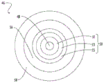
Fig. 5 shows the relative refractive index profile of a single mode fiber in accordance with some embodiments of the present disclosure.
Fig. 6 shows a relative refractive index profile of an optical fiber according to an embodiment of the present disclosure.
Fig. 7 shows a relative refractive index profile of an optical fiber according to an embodiment of the present disclosure.
Fig. 8 shows puncture load intensity as a function of cross-sectional area of a high modulus coating according to the present disclosure.
Fig. 9 shows the relative refractive index profile of a single mode fiber in accordance with some embodiments of the present disclosure.
FIG. 10 is a schematic diagram of core and cladding mode distribution of an optical fiber having a thick coating according to some embodiments of the present disclosure.
FIG. 11 is a schematic diagram of core and cladding mode distribution of an optical fiber with a thin coating according to some embodiments of the present disclosure.
Fig. 12 shows the effect of coating material viscosity and die size on coating thickness according to some embodiments of the present disclosure.
Fig. 13 shows an exemplary parameter window for forming a target final coating diameter in accordance with some embodiments of the present disclosure.
Fig. 14 shows standard deviations of coating thickness from various coating material viscosities for different die size systems in accordance with some embodiments of the present disclosure.
Fig. 15 shows the effect of draw speed on coating thickness according to some embodiments of the present disclosure.
Fig. 16 shows a graph plotting the correlation between lubrication pressure and die size for a range of coating material viscosities in accordance with some embodiments of the present disclosure.
Fig. 17 shows a correlation between lubrication pressure and draw speed in accordance with some embodiments of the present disclosure.
Fig. 18 shows a relative refractive index profile of a single mode fiber in accordance with some embodiments of the present disclosure.
FIG. 19 shows Microbending Attenuation Penalty (MAP) versus low modulus coating thickness for an optical fiber having a step index and dip assist fiber profile and a 100 micron cladding diameter according to some embodiments of the present disclosure.
FIG. 20 shows Microbending Attenuation Penalty (MAP) versus low modulus coating thickness for optical fibers with depressed auxiliary fiber profile and 100 micron cladding diameter for different moduli of the high modulus coating in accordance with some embodiments of the present disclosure.
FIG. 21 shows the stab resistance versus low modulus coating thickness for optical fibers with depressed auxiliary fiber profile and 100 micron cladding diameter for different moduli of the high modulus coating in accordance with some embodiments of the present disclosure.
FIG. 22 shows Microbending Attenuation Penalty (MAP) versus low modulus coating thickness for optical fibers with depressed auxiliary fiber profile and 100 micron cladding diameter for different moduli of the low modulus coating in accordance with some embodiments of the present disclosure.
Detailed Description
The present disclosure is provided as a enabling teaching and may be more readily understood by reference to the following description, drawings, embodiments and claims. To this end, those skilled in the art will recognize and appreciate that various modifications can be made to the various aspects of the embodiments described herein, while still obtaining the beneficial results. It will also be apparent that some of the desired beneficial results of the present embodiments can be obtained by selecting some of the features without utilizing other features. Accordingly, those who work in the art will recognize that many modifications and adaptations are possible and can even be desirable in certain circumstances and are a part of the present disclosure. Therefore, it is to be understood that this disclosure is not limited to the specific compositions, articles, devices, and methods disclosed unless otherwise specified. It is also to be understood that the terminology used herein is for the purpose of describing particular aspects only and is not intended to be limiting.
In this specification and in the claims that follow, reference will be made to a number of terms, which shall be defined to have the following meanings:
"optical fiber" refers to a waveguide with a glass portion surrounding a coating. The glass portion includes a core and a cladding, and is referred to herein as a "glass fiber".
"radial position", "radius" or radial coordinate "r" refer to a radial position relative to the centerline of the fiber (r=0).
Unless otherwise indicated, "refractive index" refers to the refractive index at a wavelength of 1550 nm.
The "refractive index profile" is the relationship between refractive index or relative refractive index and radius. For the relative refractive index profiles shown herein having stepped boundaries between adjacent core and/or cladding regions, normal variations in processing conditions may preclude sharp stepped boundaries from being obtained at the interfaces of adjacent regions. It is to be understood that while the boundaries of the refractive index profile may be shown herein as stepped changes in refractive index, in practice the boundaries may be rounded or any other way deviate from the perfect stepped functional characteristics. It is also understood that the relative refractive index values may vary with radial position in the core region and/or any cladding region. When the relative refractive index varies with radial position in a particular region of the fiber (e.g., the core region and/or any cladding region), it may be expressed in terms of its actual or approximate functional dependence, or its value at a particular location within the region, or in terms of an average value applicable to the region as a whole. Unless otherwise indicated, if the relative refractive index of a region (e.g., a core region and/or any cladding region) is expressed in terms of a single value or as a parameter (e.g., Δ or Δ%) applicable to the region as a whole, it is to be understood that the relative refractive index in the region is constant or approximately constant and corresponds to the single value or parameter represents an average value of the non-constant relative refractive index that depends on the radial position in the region. For example, if "i" is a region of glass fiber, the parameter delta, unless otherwise specified i Refers to the average value of the relative refractive index in this region as defined by the following equation (1). The dependence of the relative refractive index on radial position may be slanted, curved, or otherwise non-constant, whether as a result of design or normal manufacturing variations.
As used herein, "relative refractive index" is defined as in equation (1):

in the formula, n, unless otherwise indicated i Is the radial position r in the glass fiber i Refractive index at; unless otherwise indicated, n ref Is the refractive index of pure silica glass. Thus, as used herein, the relative refractive index percentage is relative to pure silica glass (having a value of 1.444 at a wavelength of 1500 nm). As used herein, the relative refractive index is expressed as Δ (or "Δ") or Δ% (or "Δ%") unless otherwise indicated, and the units of the values are "%". The relative refractive index may also be expressed as Δ (r) or Δ (r)%.
Average relative refractive index (delta) of a region of an optical fiber Average of ) Determined by equation (2):

wherein r is Inner part Is the inner radius of the region, r Outer part Is the outer radius of the region and delta (r) is the relative refractive index of the region.
Commercially available devices may be employed, for example: an IFA-100 fiber refractive index profiler (international fiber optic analysis limited (Interfiber Analysis LLC, sharp, MA USA) OR an S14 refractive index profiler (Photon Kinetics, inc., beaeverton, OR USA) in oregon, to measure the refractive index profile of the fiber. These devices measure the refractive index (n (r) -n relative to a measured reference refractive index meas ) In the formula, the reference refractive index n is measured meas Is a calibrated refractive index that is typically matched to oil or pure silica glass. The measurement wavelength may be: 632.5nm, 654nm, 677.2nm, 654nm, 702.3nm, 729.6nm, 759.2nm, 791.3nm, 826.3nm, 864.1nm, 905.2nm, 949.6nm, 997.7nm, 1050nm, or any wavelength therebetween. The absolute refractive index n (r) is then used to calculate the relative refractive index as defined in equation (1).
The term "α -profile" or "α -profile" refers to a relative refractive index profile Δ (r) having a functional form defined by equation (3):

wherein r is o Is the radial position at which delta (r) is the maximum, delta (r) 0 )>0,r z >r 0 Is the radial position at which delta (r) decreases to its minimum value, and r is in the range r i ≤r≤r f Wherein, r is i Is the initial radial position of the alpha-distribution, r f Is the final radial position of the α -distribution and α is a real number. Delta in this context, delta (r 0 ) May be referred to as delta max Or delta when referring to a specific region i of the fiber imax . When the relative refractive index profile of the core region of the fiber is described by an alpha-profile, and r 0 Located at the center line (r=0) and r z Outer radius r of corresponding core region 1 And delta 1 (r 1 ) =0, equation (3) is simplified to equation (4):

When the core region has a refractive index as described in equation (4), the outer radius r can be determined from the measured relative refractive index profile by 1 . Maximum relative refractive index delta 1max Alpha and outer radius r 1est Is obtained by examination of the measured relative refractive index profile and is used to generate r= -r 1est And r=r 1est Heuristic function delta between Heuristics . Shown in fig. 5 and 6 are relative refractive index profiles of representative glass fibers having cores described by alpha-profiles in accordance with embodiments of the present disclosure.
The "pit volume" is defined as follows:

wherein r is Concave, inner Is the inner radius of the depressed region of the refractive index profile, r Concave, outer Is the outer radius, delta, of the depressed region of the refractive index profile Recess in the bottom of the container (r) is the relative refractive index of the depressed region of the refractive index profile, and r is the radial position in the fiber. The depression volume is absolute and positive, the units expressed herein are as follows: % delta micrometers 2 % delta-micron 2 、%Δ-μm 2 Or% Deltaμm 2 These units are used interchangeably herein. The depressed region is also referred to herein as a depressed index cladding region, and the depressed volume is also referred to herein as V 3 。
The "mode field diameter" or "MFD" of an optical fiber is defined by equation (6):
MFD=2w

Where f (r) is the transverse component of the electric field distribution of the guided optical signal and r is the radial position in the fiber. The "mode field diameter" or "MFD" is dependent on the wavelength of the optical signal and is recorded herein for the case of wavelengths of 1310nm, 1550nm and 1625 nm. Wavelength is specifically indicated when reference is made herein to mode field diameter. Unless otherwise indicated, mode field diameter refers to LP at a particular wavelength 01 A mode.
The definition of the "effective area" of the optical fiber is as in equation (7):

where f (r) is the transverse component of the electric field of the optical signal and r is the radial position in the fiber. "effective area" or "A eff "depends on the wavelength of the optical signal and it is understood that in this context reference is made to a wavelength of 1550 nm.
As used herein, the term "attenuation" is the loss of optical power as a signal propagates along an optical fiber. Attenuation is measured by the IEC-60793-1-40 standard ("Attenuation measurement methods (attenuation measurement method)").
The bending resistance of an optical fiber can be measured herein by induced attenuation under specified test conditions as specified by the IEC-60793-1-47 standard ("Measurement methods and test procedures-Macrobending loss (measurement method and test protocol: macrobending loss)") expressed as "bending loss". For example, the test conditions may include deploying or winding the optical fiber one or more turns around a mandrel of a prescribed diameter, e.g., winding 1 turn around a mandrel of 15mm, 20mm, or 30mm or similar diameter (e.g., "1 x 15mm diameter bend loss" or "1 x 20mm diameter bend loss" or "1 x 30mm diameter bend loss") and measuring the attenuation increase per turn.
As used herein, "cable cutoff wavelength" or "cable cutoff" refers to the 22m cable cutoff test specified by the IEC 60793-1-44 standard ("Measurement methods and test procedures-Cut-off wavelength").
The optical fiber disclosed herein includes: a core region, a cladding region surrounding the core region, and a coating surrounding the cladding region. The core region and the cladding region are glass. The cladding region includes a plurality of regions. The regions of the plurality of cladding layers are preferably concentric regions. The cladding region includes an inner cladding region, a depressed index cladding region, and an outer cladding region. The inner cladding region surrounds and is immediately adjacent to the core region. The depressed index cladding region surrounds and is directly adjacent to the inner cladding region such that the depressed index cladding region is disposed between the inner cladding and the outer cladding in a radial direction. The outer cladding region surrounds and is immediately adjacent to the depressed index region. The depressed index region has a relative refractive index lower than the inner cladding and outer cladding regions. Depressed index cladding regions may also be referred to herein as depressions or depressed regions. The relative refractive index of the inner cladding region may be less than, equal to, or greater than the relative refractive index of the outer cladding region. The depressed index cladding region may serve to reduce bending losses and microbending sensitivity. The core region, inner cladding region, depressed index cladding region, and outer cladding region are also referred to as the core, cladding, inner cladding, depressed index cladding, and outer cladding, respectively.
As used anywhere herein, the radial position r 1 And relative refractive index delta 1 Or delta 1 (r) relates to the core region, radial position r 2 And relative refractive index delta 2 Or delta 2 (r) relates to the inner cladding region, radial position r 3 And relative refractive index delta 3 Or delta 3 (r) relates to depressed index cladding region, radial position r 4 And relative refractive index delta 4 Or delta 4 (r) relates to the outer cladding region, radial position r 5 Involving an optional low modulus internal coating, radial position r 6 Involving a high modulus coating, and a radial position r 7 To an optional pigment overcoat.
Relative refractive index delta 1 (r) has a maximum value of delta 1max And a minimum value delta 1min . Relative refractive index delta 2 (r) has a maximum value of delta 2max And a minimum value delta 2min . Relative refractive index delta 3 (r) has a maximum value of delta 3max And a minimum value delta 3min . Relative refractive index delta 4 (r) has a maximum value of delta 4max And a minimum value delta 4min . In embodiments where the relative refractive index is constant or approximately constant over the area, the maximum and minimum values of the relative refractive index are equal or approximately equal. Unless otherwise indicated, a single value corresponds to the average value for a region if it is recorded for the relative refractive index of that region.
It is understood that the central core region is substantially cylindrical in shape and the surrounding inner cladding region, depressed index cladding region, outer cladding region, low modulus coating and high modulus coating are substantially annular in shape. The annular region may be characterized by an inner radius and an outer radius. Herein, the radial position r 1 、r 2 、r 3 、r 4 、r 5 、r 6 And r 7 Involving a core, an inner cladding, and a dip, respectivelyRefractive index cladding, outer cladding, low modulus inner coating, high modulus coating, and optionally outermost radius of pigment outer coating. In embodiments without a pigment overcoat, radius r 6 But also to the outer radius of the optical fiber. The pigment overcoat may have a high modulus. Radius r when pigment overcoat is present 7 Corresponding to the outer radius of the optical fiber.
When the two regions are directly adjacent to each other, the outer radius of the inner one of the two regions is coincident with the inner radius of the outer one of the two regions. For example, the optical fiber includes a depressed index cladding region surrounded by and immediately adjacent to an outer cladding region. Radius r 3 Corresponding to the outer radius of the depressed index cladding region and the inner radius of the outer cladding region. The relative refractive index profile also includes a depressed index cladding region surrounding and immediately adjacent to the inner cladding region. Radial position r 2 Corresponding to the outer radius of the inner cladding region and the inner radius of the depressed index cladding region. Similarly, radial position r 1 Corresponding to the outer radius of the core region and the inner radius of the inner cladding region.
Radial position r 2 And radial position r 1 The difference is referred to herein as the thickness of the inner cladding region. Radial position r 3 And radial position r 2 The difference is referred to herein as the thickness of the depressed index cladding region. Radial position r 4 And radial position r 3 The difference is referred to herein as the thickness of the outer cladding region. Radial position r 5 And radial position r 4 The difference is referred to herein as the thickness of the low modulus coating. Radial position r 6 And radial position r 5 The difference is referred to herein as the thickness of the high modulus coating.
As described in further detail below, the relative refractive indices of the core region, inner cladding region, depressed index cladding region, and outer cladding region may be different. Each of the regions may be formed of doped or undoped silica glass, respectively. The change in refractive index relative to undoped silica glass can be accomplished by combining positive or negative dopants at levels designed to provide a target refractive index or refractive index profile using techniques known to those skilled in the art. A positive dopant is a dopant that increases the refractive index of the glass relative to the undoped glass composition. A negative dopant is a dopant that reduces the refractive index of the glass relative to the undoped glass composition. In one embodiment, the undoped glass is silica glass. When the undoped glass is silica glass, the positive dopants include Cl, br, ge, al, P, ti, zr, nb, and Ta, and the negative dopants include fluorine and boron. The region of constant refractive index may be formed by undoped or doped at a uniform concentration throughout the thickness of the region. The regions of varying refractive index are formed by non-uniform spatial distribution of dopants across the thickness of the region and/or by combining different dopants in different regions.
The values of Young's modulus,% tensile and tear strength refer to the values determined under the measurement conditions of the protocol described herein.
Reference will now be made in detail to exemplary embodiments of the present specification.
One embodiment relates to an optical fiber. The optical fiber includes a glass fiber surrounded by a coating. Fig. 1 shows an example of an optical fiber in a schematic cross-sectional view. The optical fiber 10 includes a glass fiber 11 surrounded by an optional low modulus inner coating 16 and a high modulus coating 18. In some embodiments, high modulus coating 18 may include pigments. Further description of the glass fibers 11, the optional low modulus inner coating 16, and the high modulus coating 18 is provided below. In addition, one or more pigment outer coating layers may surround the high modulus coating 18.
Fig. 2 shows an optical fiber ribbon 30 that may include a plurality of optical fibers 20 and a matrix 32 encapsulating the plurality of optical fibers. Each of the optical fibers 20 includes: the core region, the cladding region, the optional low modulus inner coating, and the high modulus coating, as described above. As described above, the optical fiber 20 may also include a pigment overcoat.
As shown in fig. 2, the optical fibers 20 are aligned with one another in a substantially planar and parallel relationship. The optical fibers are encapsulated in the optical fiber ribbon 30 with the ribbon matrix 32 by any of a number of known configurations (e.g., edge-bonded ribbon, thin-encapsulated ribbon, thick-encapsulated ribbon, or multi-layer ribbon) by conventional methods of manufacturing optical fiber ribbons. The ribbon 30 in the embodiment of fig. 2 contains twelve (12) optical fibers 20. However, it is contemplated that any number of optical fibers 20 (e.g., 2 or more, 4 or more, 6 or more, 8 or more, 12 or more, or 16 or more) may be used to form a particular use of the optical fiber ribbon 30. The tensile properties of the tape substrate 32 are similar to those of the high modulus coating and may be formed from the same, similar, or different compositions used to prepare the high modulus coating.
Fig. 3 shows a fiber optic cable 40 that includes a plurality of optical fibers 20 surrounded by a jacket 42. In some embodiments, fiber optic cable 40 is a submarine cable. In some embodiments, fiber optic cable 40 is a fiber optic ribbon used in an interconnection scheme in a data center. The optical fiber 20 may be packaged in a dense or loose manner into a catheter that is enclosed by the inner surface 44 of the jacket 42. The number of optical fibers placed in jacket 42 is referred to as the "fiber count" of fiber optic cable 40. As discussed further below, the optical fibers of the present disclosure have a reduced diameter, thereby providing a high "fiber count".
Jacket 42 is formed from an extruded polymeric material and may include multiple concentric layers of polymer or other materials. The fiber optic cable 40 may include one or more strength members (not shown) embedded in the jacket 42 or disposed in a conduit defined by the inner surface 44. The reinforcing elements comprise fibers or rods that are more rigid than the jacket 42. The reinforcing elements may be made of metal, woven steel, glass reinforced plastic, fiberglass, or other suitable materials. The fiber optic cable 40 may include other layers (e.g., protective layers, moisture barriers, tear lines, etc.) surrounded by a jacket 42. Furthermore, the fiber optic cable 40 may have a stranded loose tube core or other fiber optic cable configuration.
Glass fiber
As shown in fig. 1, the glass fiber 11 includes a core region 12 and a cladding region 14, as is known in the art. The core region 12 has a higher refractive index than the cladding region 14, and the glass fiber 11 acts as a waveguide. In many applications, the core region 12 and the cladding region 14 have distinguishable core-cladding boundaries. Alternatively, the core region 12 may lack a distinguishable boundary from the cladding region 14.
In some embodiments, the core region 12 has a refractive index that varies with distance from the center of the glass fiber. For example, the core region 12 may have a relative refractive index profile of an α -profile (as defined in equation (3) above), the α value being greater than or equal to 2 and less than or equal to 100, or, for example, the α value being: greater than or equal to 2 and less than or equal to 10, or greater than or equal to 2 and less than or equal to 6, or greater than or equal to 2 and less than or equal to 4, or greater than or equal to 4 and less than or equal to 20, or greater than or equal to 6 and less than or equal to 20, or greater than or equal to 8 and less than or equal to 20, or greater than or equal to 10 and less than or equal to 40.
A schematic cross-sectional view of an exemplary optical fiber is shown in fig. 4. In some embodiments, the optical fiber of fig. 4 may be used in an undersea optical cable or optically connected to a component in an undersea repeater. In some embodiments, the optical fibers of fig. 4 may be used for data center interconnection. In fig. 4, the optical fiber 46 includes: a core region 48, a cladding region 50, an optional low modulus inner coating 56, and a high modulus coating 58. The cladding region 50 includes: an inner cladding region 51, a depressed index cladding region 53, and an outer cladding region 55. A pigment overcoat (e.g., ink layer) optionally surrounds or is directly adjacent to the high modulus coating.
As discussed above, the optical fiber 46 may have a reduced coating diameter. Such reduced diameters may increase the fiber density (e.g., the "fiber count") of the optical fibers 46, for example, when used in a submarine cable or repeater or data center interconnection. To provide low attenuation, large effective area, low bending losses, and sufficiently high mechanical reliability for an optical fiber 46 having a smaller diameter, the properties of the optical fiber are specifically tailored, as discussed further below.
Shown in fig. 5 is a representative relative refractive index profile of a glass fiber according to an embodiment of the present disclosure. The distribution of the optical fiber 60 of fig. 5 shows: a core region (1) having an outer radius r 1 And relative refractionRate delta 1 The refractive index delta 1 With a maximum relative refractive index delta 1max The method comprises the steps of carrying out a first treatment on the surface of the An inner cladding region (2) from a radial position r 1 Extends to a radial position r 2 And has a relative refractive index delta 2 The method comprises the steps of carrying out a first treatment on the surface of the Depressed index cladding region (3) from radial position r 2 Extends to a radial position r 3 And has a relative refractive index delta 3 The method comprises the steps of carrying out a first treatment on the surface of the And an outer cladding region (4) from a radial position r 3 Extends to a radial position r 4 And has a relative refractive index delta 4 . In the distribution of fig. 5, depressed index cladding region (3) may be referred to herein as depressed and has a constant or average relative refractive index that is less than the relative refractive indices of inner cladding region (2) and outer cladding region (4). The core region (1) has the highest average and maximum relative refractive indices in the distribution. In some embodiments, the core region (1) may have a lower refractive index region at or near the centerline (known in the art as "centerline dip") (not shown). In some embodiments, the core region (1) may have a higher refractive index region (referred to as a "centerline spike") at or near the centerline (not shown).
In the relative refractive index profile of fig. 5, the core region (1) of the glass fiber has an α -profile, and the α value is greater than or equal to 2 and less than or equal to 20. Radial position r of alpha-distribution 0 (corresponding to delta 1max ) Corresponding to the centerline of the fiber (r=0), while the radial position r of the α -distribution z Corresponding to the core radius r 1 . In embodiments with centerline dip, the radial position r 0 May be offset from the centerline of the fiber. In some embodiments, the relative refractive index, delta, is in a radial direction away from the centerline 1 Continuously decreasing. In other embodiments, the relative refractive index delta 1 At the central line and r 1 Varying in some radial positions between and between the centerline and r 1 Other radial positions in between also include constant or approximately constant values.
In FIG. 5, transition region 61 from inner cladding region (2) to depressed index cladding region (3) and from depressed indexThe transition region 62 of the cladding region (3) to the outer cladding region (4) is shown as a stepwise change. It will be appreciated that the stepped variation is idealised and in practice the transition region 61 and/or the transition region 62 may not be exactly perpendicular as shown in figure 5. Alternatively, the transition region 61 and/or the transition region 62 may have a slope or curvature. When the transition region 61 and/or the transition region 62 are not vertical, the inner radius r of the depressed index cladding region (3) 2 And outer radius r 3 Corresponding to the midpoints of transition regions 61 and 62, respectively. The midpoint corresponds to half the depth 63 of the depressed index cladding region (3).
The relative refractive index delta in the relative refractive index distribution as shown in fig. 5 1 、Δ 2 、Δ 3 And delta 4 The relative order of (2) satisfies the following condition: delta 1max >Δ 4 >Δ 3 And delta is 1max >Δ 2 >Δ 3 。Δ 2 And delta 4 May be equal or one greater than the other, but delta 2 And delta 4 Are all at delta 1max And delta 3 Between them.
Relative refractive index delta 1 、Δ 2 、Δ 3 And delta 4 Based on the materials used in the core region, inner cladding region, depressed index cladding region, and outer cladding region. The following provides for the relative refractive index delta 1 、Δ 2 、Δ 3 And delta 4 Is described in detail below.
While fig. 5 shows a schematic cross-sectional view of an exemplary optical fiber, other suitable optical fibers may be used with the embodiments described herein. For example, fig. 9 is a schematic cross-sectional view of a generic distribution design for a single-mode optical fiber that may be used in embodiments described herein. The distribution of the optical fiber of fig. 9 shows: a core region having an outer radius r 1 And relative refractive index delta 1 The method comprises the steps of carrying out a first treatment on the surface of the An inner cladding region from radial position r 1 Extends to a radial position r 2 And has a relative refractive index delta 2 The method comprises the steps of carrying out a first treatment on the surface of the Depressed index cladding region from radial position r 2 Extends to a radial position r 3 And has a relative refractive index delta 3 The method comprises the steps of carrying out a first treatment on the surface of the And an outer cladding region from radial position r 3 Extends to a radial position r 4 And has a relative refractive index delta 4 . Tables 1 and 2 below show various exemplary fiber optic distribution designs that may be used with the embodiments described herein, and table 3 shows various optical properties of various exemplary fiber optic distribution designs that may be used with the embodiments described herein.
Table 1: exemplary fiber distribution design


Table 2: exemplary fiber distribution design

Table 2 continuation

Table 3: optical properties of exemplary fiber optic distribution


Core region
The core region comprises silica glass. The silica glass of the core region may be undoped silica glass, positively doped silica glass and/or negatively doped silica glass. Positively doped dioxideThe silicate glass comprises a silicon glass doped with an alkali metal oxide (e.g., na 2 O、K 2 O、Li 2 O、Cs 2 O or Rb 2 O) silica glass. The negatively doped silica glass includes silica glass doped with F. In one embodiment, the silica glass of the core region may be Ge-free and/or Cl-free; that is, the core region comprises silica glass that does not contain Ge and/or Cl.
Additionally or alternatively, the core region may comprise silica glass doped with at least one alkali metal, such as lithium (Li), sodium (Na), potassium (K), rubidium (Rb), cesium (Cs), and/or francium (Fr). In some embodiments, the silica glass is doped with a combination of sodium, potassium, and rubidium. The peak alkaline matter concentration of silica glass may be in the following range: about 10ppm to about 500, or about 20ppm to about 450ppm, or about 50ppm to about 300ppm, or about 10ppm to about 200ppm, or about 10ppm to about 150ppm. Doping with alkali metal in the disclosed ranges results in a reduction in rayleigh scattering, providing lower fiber attenuation.
In some embodiments, the core region comprises silica glass doped with an alkali metal and doped with F as a negative dopant. The F concentration in the core of the fiber is in the following range: about 0.1 wt% to about 2.5 wt%, or about 0.25 wt% to about 2.25 wt%, or about 0.3 wt% to about 2.0 wt%.
In other embodiments, the core region comprises silica glass doped with Ge and/or Cl. GeO in the core of an optical fiber 2 The concentration may be in the following range: about 2.0 to about 8.0 wt%, alternatively about 3.0 to about 7.0 wt%, alternatively about 4.0 to about 6.5 wt%. The Cl concentration in the core of the fiber may be in the following range: 1.5 wt% to 6.0 wt%, alternatively 1.2 wt% to 5.5 wt%, alternatively 1.5 wt% to 5.0 wt%, alternatively 2.0 wt% to 4.5 wt%, alternatively greater than or equal to 1.5 wt% (e.g.,. Gtoreq.2 wt%,. Gtoreq.2.5 wt%,. Gtoreq.3 wt%,. Gtoreq.3.5 wt%,. Gtoreq.4 wt%,. Gtoreq.4.5 wt%,. Gtoreq.5 wt%, etc.).
In embodiments where the core is substantially free of Ge or ClRelative refractive index delta of core region 1 Or delta 1max The range is as follows: about-0.10% to about 0.20%, alternatively about-0.05% to about 0.15%, alternatively about 0.0% to about 0.10%. Minimum relative refractive index delta of the core 1min The range is as follows: about-0.20% to about-0.50%, alternatively about-0.30% to about-0.40%, alternatively about-0.32% to about-0.37%. Delta 1max And delta 1min The difference is: greater than 0.05%, or greater than 0.10%, or greater than 0.15%, or greater than 0.20%, or in the range of 0.05% to 0.40%, or in the range of 0.10% to 0.35%.
In embodiments where the core is doped with Ge and/or Cl, the relative refractive index of the core region, delta 1 Or delta 1max The range is as follows: about 0.20% to about 0.45%, alternatively about 0.25% to about 0.40%, alternatively about 0.30% to about 0.38%. Minimum relative refractive index delta of the core 1min The range is as follows: about-0.05% to about-0.05%, alternatively about-0.03% to about 0.03%, alternatively about-0.02% to about 0.02%. Delta 1max And delta 1min The difference is: greater than 0.20%, alternatively greater than 0.25%, alternatively greater than 0.30%, alternatively in the range of 0.25% to 0.45%, alternatively in the range of 0.30% to 0.40%.
Radius r of core region 1 The range is as follows: about 3.0 microns to about 6.0 microns, or about 3.5 microns to about 6.0 microns, or about 4.0 microns to about 6.0 microns, or about 4.5 microns to about 5.5 microns. In some embodiments, the core region includes a portion having a constant or approximately constant relative refractive index, the width of which in the radial direction is: at least 1.0 microns, or at least 2.0 microns, or at least 3.0 microns, or in the range of 1.0 microns to 3.0 microns, or in the range of 2.0 microns to 3.0 microns. In some embodiments, the portion of the core region having a constant or approximately constant relative refractive index has a relative refractive index delta 1min 。
Inner cladding region
In embodiments where the core is substantially free of Ge and Cl, the inner cladding region comprises a negatively doped silica glass doped with F. The average concentration of the negative dopant in the inner cladding region is greater than the average concentration of the negative dopant in the core region.
Relative refractive index delta of inner cladding region 2 Or delta 2max The range is as follows: about-0.20% to about-0.50%, or about-0.25% to about-0.45%, or about-0.30% to about-0.40%, or about-0.33% to about-0.37%. Relative refractive index delta 2 Preferably constant or approximately constant. Delta 1max -Δ 2 Difference (or delta) 1max -Δ 2max The difference) is: greater than about 0.25%, alternatively greater than about 0.30%, alternatively greater than about 0.35%, alternatively in the range of about 0.25% to about 0.45%, alternatively in the range of about 0.30% to about 0.40%.
Radius r of inner cladding region 2 The range is as follows: about 7.0 microns to about 15.0 microns, or about 7.5 microns to about 13.0 microns, or about 8.0 microns to about 12.0 microns, or about 8.5 microns to about 11.5 microns, or about 9.0 microns to about 11.0 microns, or about 9.5 microns to about 10.5 microns. Thickness r of inner cladding region 2 -r 1 The range is as follows: about 3.0 microns to about 10.0 microns, or about 4.0 microns to about 9.0 microns, or about 4.5 microns to about 7.0 microns.
In embodiments where the core is doped with Ge and/or Cl, the inner cladding region comprises silica that is substantially free of Ge and/or Cl. Relative refractive index delta of inner cladding region 2 Or delta 2max The range is as follows: about-0.05% to about-0.05%, alternatively about-0.03% to about 0.03%, alternatively about-0.02% to about 0.02%. Relative refractive index delta 2 Preferably constant or approximately constant. Delta 1max -Δ 2 Difference (or delta) 1max -Δ 2max The difference) is: greater than about 0.20%, alternatively greater than about 0.25%, alternatively greater than about 0.30%, alternatively in the range of about 0.25% to about 0.40%, alternatively in the range of about 0.30% to about 0.38%.
Radius r of inner cladding region 2 The range is as follows: about 8.0 microns to about 16.0 microns, or about 9.0 microns to about 15.0 microns, or about 10.0 microns to about 14.0 microns, or about 10.5 microns to about 13.5 microns, or about 11.0 microns to about 13.0 microns. Thickness r of inner cladding region 2 -r 1 The range is as follows: about 3.0 microns to about 10.0 microns, or about 4.0 microns to about 9.0 microns, or about 5.0 microns to about 8.0 microns.
Depressed index cladding region
The depressed index cladding region comprises negatively doped silica glass. As discussed above, the preferred negative dopant is fluorine. The fluorine concentration in the depressed index cladding region is in the following range: about 0.30 wt% to about 2.50 wt%, or about 0.60 wt% to about 2.25 wt%, or about 0.90 wt% to about 2.00 wt%.
Relative refractive index delta 3 Or delta 3min The range is as follows: about-0.30% to about-0.80%, alternatively about-0.40% to about-0.70%, alternatively about-0.50% to about-0.65%. Relative refractive index delta 3 Preferably constant or approximately constant. Delta 1max -Δ 3 Difference (or delta) 1max -Δ 3min Difference, or delta 1 -Δ 3 Difference, or delta 1 -Δ 3min The difference) is: greater than about 0.50%, alternatively greater than about 0.55%, alternatively greater than about 0.6%, alternatively in the range of about 0.50% to about 0.80%, alternatively in the range of about 0.55% to about 0.75%. Delta 2 -Δ 3 Difference (or delta) 2 -Δ 3min Difference, or delta 2max -Δ 3 Difference, or delta 2max -Δ 3min The difference) is: greater than about 0.10%, alternatively greater than about 0.20%, alternatively greater than about 0.30%, alternatively in the range of about 0.10% to about 0.70%, alternatively in the range of about 0.20% to about 0.65%.
The inner radius of the depressed index cladding region is r 2 And has the values specified above. Outer radius r of depressed index cladding region 3 The range is as follows: about 10.0 microns to 20.0 microns, or about 12.0 microns to about 19.5 microns, or about 13.0 microns to about 19.0 microns, or about 13.5 microns to about 18.5 microns, or about 14.0 microns to about 18.0 microns, or about 14.5 microns to about 17.5 microns. Thickness r of depressed index cladding region 3 -r 2 The range is as follows: 1.0 microns to 12.0 microns, or about 2.0 microns to about 10.0 microns, or about 2.5 micronsMeter to about 9.0 microns, or about 3.0 microns to about 8.0 microns.
The depressed index cladding region may be an offset depressed design, having a depressed volume as follows: about 30% delta-micron 2 Or greater, or about 50% delta-microns 2 Or greater, or about 75% delta-microns 2 Or less, or about 30% delta-microns 2 Or greater and about 75% delta-microns 2 Or less, or about 50% delta-microns 2 Or greater and about 75% delta-microns 2 Or smaller. A depressed volume below the disclosed range has reduced bending properties, while a depressed volume above the disclosed range no longer operates as a single mode fiber.
The offset dimple designs disclosed herein include an inner cladding region. Furthermore, the offset groove designs disclosed herein provide advantages over conventional recess designs adjacent to the core region. More specifically, the offset notch designs disclosed herein reduce fundamental mode confinement and provide improved bend loss at large bend diameters (e.g., bend diameters >25 mm) for target fiber mode field diameters and cable cut-off characteristics. Furthermore, the depressed designs disclosed herein have depressed index depressed regions that advantageously limit the intensity distribution of the fundamental LP01 mode propagating through the fiber, thereby reducing the fiber mode field diameter.
Outer cladding region
In embodiments where the core is substantially free of Ge and Cl, the outer cladding region comprises negatively doped silica glass. The preferred negative dopant is fluorine. The fluorine concentration in the overclad region is in the following range: about 0.30 wt% to about 2.20 wt%, or about 0.60 wt% to about 2.00 wt%, or about 0.90 wt% to about 1.80 wt%. Relative refractive index delta of the overclad region 4 Or delta 4max The range is as follows: about-0.20% to about-0.50%, or about-0.25% to about-0.45%, or about-0.30% to about-0.40%, or about-0.33% to about 0.37%. Relative refractive index delta 4 Preferably constant or approximately constant. As shown in fig. 5, the relative refractive index delta 4 Can be approximately equal to the relative refractive index delta 2 。
In an embodiment, the outer cladding is substantially pure silica. Alternatively, the overclad may be doped with Cl to a relative refractive index in the range: about 0.01 to about 0.1%, alternatively about 0.02% to about 0.08%, alternatively about 0.03% to about 0.06%. The Cl concentration in the overclad may be in the following range: about 0.1 wt% to about 1.0 wt%, about 0.2 wt% to about 0.8 wt%, or about 0.3 wt% to about 0.6 wt%. Alternatively, the outer cladding may be doped with titanium oxide to strengthen the cladding surface to prevent defects such as scratches from propagating through the fiber. In some embodiments, the outer cladding may be doped with a titanium oxide concentration of about 5 wt% to about 25 wt%.
The inner radius of the outer cladding region is r 3 And has the values specified above. In some embodiments, the outer radius r 4 About 62.5 microns to facilitate splicing with conventional 125 micron cladding diameter fibers using a cladding aligned splice. Outer radius r of outer cladding region 4 The range is as follows: 60.0 to 65.0 microns, alternatively 61.0 to 64.0 microns, alternatively 62.0 to 63.0 microns, alternatively 62.25 to 62.75 microns. Thus, for example, the diameter of the cladding region (i.e., outer radius r 4 Multiplying by 2) is the following range: 120.0 to 130.0 microns, or 122.0 to 128.0 microns, or 124.0 to 126.0 microns, or 124.5 to 125.5 microns. Thickness r of the outer cladding region 4 -r 3 The range is as follows: about 20.0 microns to about 60.0 microns, or about 30.0 microns to about 55.0 microns, or about 40.0 microns to about 50.0 microns. In some embodiments, the outer radius r 4 About 50 microns to achieve an increase in thickness of the low modulus and high modulus coatings. Outer radius r of outer cladding region 4 The range is as follows: 45.0 to 55.0 microns, alternatively 49.0 to 51.0 microns, alternatively 49.5 to 50.5 microns, alternatively 49.65 to 50.35 microns. Thus, for example, the diameter of the cladding region (i.e., outer radius r 4 Multiplying by 2) is the following range: 90.0 to 110.0 microns, or 98.0 to 102.0 microns, or 99.0 to 101.0 microns, or 99.3 to 100.7 microns. Thickness r of the outer cladding region 4 -r 3 The range is as follows: about 20.0 microns to about 50.0 microns, or about 25.0 microns to about 45.0 microns, or about 30.0 microns to about 40.0 microns.
Optical fiber characteristics
An optical fiber according to embodiments of the present disclosure may have a mode field diameter in the following range: about 9.0 microns to about 10.0 microns at 1310nm and about 10.0 microns to about 11.0 microns at 1550nm, the cable cutoff is less than about 1520nm. In some embodiments, the 22 meter cable cutoff wavelength is: less than about 1550nm, or less than about 1450nm, or less than about 1400nm, or less than about 1300nm, or less than about 1260nm. In some embodiments, the 2 meter fiber cutoff wavelength is: less than about 1520nm, or less than about 1500nm, or less than about 1450nm, or less than about 1400nm, or less than about 1300nm, or less than about 1260nm.
Further, an optical fiber according to an embodiment of the present disclosure may have the following effective area at 1550 nm: greater than about 75.0 microns 2 Greater than about 80 microns 2 Or greater than about 85 microns 2 Or about 75 microns 2 Up to about 95 microns 2 In the range of, or about 80 microns 2 Up to about 90 micrometers 2 Or about 85 microns 2 Up to about 90 micrometers 2 Is not limited in terms of the range of (a).
The attenuation of the optical fibers disclosed herein is: less than or equal to 0.36dB/km at 1310nm, or less than or equal to 0.30dB/km, or less than or equal to 0.28dB/km, or less than or equal to 0.26dB/km at 1310 nm. At 1550nm wavelength, the attenuation of the optical fiber disclosed herein is: less than or equal to 0.24dB/km, or less than or equal to 0.22dB/km, or less than or equal to 0.20dB/km.
As shown in fig. 5, an optical fiber 60 provides an exemplary embodiment of an optical fiber having an alkaline-doped core, the relative refractive index delta of the core region (1) 1 From about-0.3% to about-0.42%, and a core radius (r 1 ) From about 4 microns to about 6.5 microns. In addition, the inner cladding region of the optical fiber 60 has a thickness of about 2 microns to about 12 microns. The fiber 60 has a depressed volume of 54.5% delta-microns 2 Is a design of the offset recess. The cladding of the fiber 60 is fluorine doped and the lower index cladding region hasHas a radius (r) of about 17.5 microns 3 ). Table 4 below shows the optical properties of the optical fiber 60.
Table 4: optical properties of the optical fiber 60


FIG. 6 shows second and third exemplary embodiments of optical fibers (64 and 65) having an alkaline-doped core and greater than about 50% delta-microns 2 Wherein the cladding is fluorine doped and the lower index cladding region has a radius (r) of about 17.5 microns 3 ). As shown in table 5 below, fiber 64 resulted in a mode field diameter of 9.07 microns at 1310nm, while fiber 65 resulted in a mode field diameter of 9.39 microns at 1310 nm. Table 2 below shows the optical properties of fibers 64 and 65.
Table 5: optical properties of optical fibers 64 and 65
| Optical fiber 64 | Optical fiber 65 | |
| Mode field diameter (1310 nm) | 9.07 micrometers | 9.39 micrometers |
| Mode field diameter (1550 nm) | 10.08 micrometers | 10.48 micrometers |
| Mode field diameter (1625 nm) | 10.41 micrometers | 10.83 micrometers |
| Zero dispersion wavelength | 1319nm | 1320nm |
| Optical cable cut-off | 1419nm | 1339nm |
| Volume of recess | 55% delta-micron 2 | 55% delta-micron 2 |
| 15mm diameter bending loss | 0.0137 dB/turn | 0.042 dB/turn |
| 20mm diameter bending loss | 0.0003 dB/turn | 0.009 dB/turn |
| Bending loss of 30mm diameter | 0.0002 dB/turn | 0.001 dB/turn |
FIG. 7 shows an embodiment of an optical fiber 66 having a Ge doped core with greater than 50% delta-microns 2 And wherein the inner and cladding regions are substantiallyThe pure silica and depressed index cladding region have a radius (r) of about 16.8 microns 3 ). As shown in table 6 below, the optical fiber 64 resulted in a mode field diameter of 10.6 microns at a wavelength of 1550 nm. Table 6 below shows refractive index profile parameters and optical properties of the optical fiber 66.
Table 6: optical properties of optical fiber 66


The offset concave design of fibers 60, 64, 65 and 66 provides improved bending performance for the smaller diameter fibers disclosed herein. More specifically, the offset dimple design disclosed herein provides low attenuation, large effective area, and low bending losses in a compact form, with a cladding diameter of about 125 microns and an overcoat diameter of less than 175 microns.
Coating Properties
The transmission coefficient of light through an optical fiber is highly dependent on the nature of the coating applied to the glass fiber. As discussed above (and with reference to fig. 4), the coating may include an optional low modulus inner coating 56 and a high modulus coating 58, wherein the high modulus coating surrounds the optional low modulus inner coating and the optional low modulus inner coating contacts the glass fibers (which includes a central core region surrounded by a cladding region). An optional pigment overcoat (e.g., ink layer) surrounds and directly contacts the high modulus coating.
The high modulus coating 58 is a harder material (higher Young's modulus) than the optional low modulus coating 56 and is designed to protect the glass fiber from damage caused by abrasion or external forces during processing, handling and deployment of the fiber. The optional low modulus inner coating 56 is a softer material (lower Young's modulus) than the high modulus coating 58 and is designed to buffer or dissipate stresses due to forces applied to the outer surface of the high modulus coating. The optional low modulus coating may help dissipate stresses due to microbending encountered by the optical fiber when disposed in the fiber optic cable, but is not necessary for short length applications (e.g., optical interconnects). It is desirable to minimize the microbending stress transmitted to the glass fibers because the microbending stress creates localized disturbances in the refractive index profile of the glass fibers. The local refractive index perturbations result in a loss of intensity of the light transmitted through the glass fiber. By dissipating the stress, the optional low modulus coating minimizes the loss of strength due to microbending.
Thinner coatings on optical fibers are believed to increase microbending losses because they provide less protection against external disturbances. These perturbations cause the guided light in the core (core mode) to couple power to higher order modes in the cladding (cladding modes). As shown in fig. 10, the cladding modes will have significant overlap with the highly absorbing paint layer. This coupling and the absorption process of the coating material result in optical power losses.
The following papers disclose schemes for quantifying coating properties and microbending losses of optical fibers, J.Baldauf, N.Okada and m.miyamoto, entitled "Relationship of Mechanical Characteristics of Dual Coated Single Mode Fibers and Microbending Loss (relationship between mechanical properties of double coated single mode fiber and microbending losses)", IEICE communication transactions, volume E76-B, phase 4, pages 352-357 (1993, month 4). The authors introduced the parameter χ s This is the effective spring constant for the forces coupling the secondary (high modulus) coating to the glass fiber. This spring constant parameterization provides reinforcement guidance, namely: thick primary (low modulus) coatings with low modulus provide better microbending properties, but it does not fully capture the contribution of glass and high modulus coatings.
The combination of roles of glass, low modulus undercoats and high modulus coatings results in the following microbending decay penalty (MAP):

wherein f 0 And sigma are respectivelyStandard deviation of average transverse pressure and roughness of outer surface in contact with high modulus coating, and
f RIP the role of the refractive index distribution is taken into account and is order unit (order unit). The attenuation data shows that for single mode fibers with stepped refractive index profile, f RIP Approximately 1.0; and about 0.5 for a bend insensitive single mode fiber having a refractive index profile comprising a depressed index dip in the cladding. The other three terms in equation 8 are the corresponding contribution to microbending of glass, low modulus undercoats, and systems comprising low modulus undercoats and high modulus undercoats, and are as follows:


and
Wherein R is g Is the radius of the glass (i.e., the outer radius of the outer cladding region), R s Is the outer radius, t, of the high modulus overcoat p Is the thickness of the low modulus inner coating, t s Is the thickness of the high modulus overcoat and E g 、E p And E is s The elastic moduli of the glass, the low modulus inner coating and the high modulus coating, respectively. When the units of modulus and radius are GPa and micron, respectively, the units of MAP are dB/km. Low modulus internal coating coefficient f p Depending on (1/t) p ) 2 Not just 1/t p (this is the case for spring constant parametric predictions). f (f) cs The coating system coefficient is interesting for optical fibers with thinner coatings because when the high modulus coating is thicker (t s Greater than about 20 micronsMeter) that is very large, which corresponds to a low MAP. However, when the high modulus coating thickness t s Below about 10 microns, it becomes quite small and gives a MAP value greater than 0.01dB/km, which is the result of the reduced stiffness of the overcoat. The fiber attenuation is assumed to be approximately 0.19db.km without any microbending attenuation penalty, so that the net attenuation of the coated fiber system is 0.19dB/km plus the microbending attenuation penalty.
The inventors have found that microbending losses can be reduced if the coating is below a certain thickness (as described herein). As shown in fig. 11, when the thickness of the polymer coating is sufficiently reduced, there is an anti-resonance effect in the coating layer, which makes light not guided in the coating layer. This anti-resonance effect significantly reduces the absorption of the paint layer, thereby reducing microbending losses. Conventional coating thicknesses greater than 37 microns are too large for anti-resonance effects. To produce this anti-resonance effect, the total thickness of the polymer coating is less than 25 microns, more preferably less than 20 microns, and even more preferably less than 10 microns. In some embodiments, the total thickness of the polymeric coating is: about 2 microns to about 25 microns, or about 2 microns to about 20 microns, or about 2 microns to about 15 microns, or about 2 microns to about 10 microns, or about 2 microns to about 5 microns.
As used herein, the term "penetration load" refers to the amount of action impinging on a coating of an optical fiber as described herein. As used herein, the term "stab resistance" refers to the force from the fiber coating against the stab load. As described further below, the coating may fracture when the puncture load exceeds the maximum puncture resistance of the coating. For puncture resistance, analysis of optical fibers having one type of coating in Glaeseman and Clark article "Quantifying the Puncture Resistance of Optical Fiber Coatings (quantification of puncture resistance for optical fiber coatings)" (Proc. 52 IWCS, pages 237-245 (1993)) shows that puncture resistance is relative to the cross-sectional area A of a high modulus coating s Has a linear dependence. The analysis in this paper assumes that the puncture resistance is due to hoop stress on the high modulus coating, which they model as thin cylinders that are subject to internal pressure from the low modulus inner coating.However, for most optical fibers, the thickness t of the high modulus coating s And outer radius r 6 The ratio is on the order of about 10%, so the low modulus coating of the fiber can be approximated as a thick walled cylinder, pressure P o From the outside and transmits the puncture load. In the extreme case where the external pressure is much greater than the internal pressure from the low modulus inner coating, the maximum hoop stress is  Wherein A is S Is the cross-sectional area of the high modulus coating. This hoop stress was observed for A s With inverse correlation, then the puncture resistance is P R =P 0 +C 1 E s A s Wherein E is S Is the modulus of the high modulus coating and the coefficient P 0 And C 1 The values of (C) are about 11.3g and 2.1g/MPa/mm, respectively 2 。
Coating examples: preparation and measurement techniques
The properties of the optional low modulus inner and high modulus coatings disclosed herein were determined using the measurement techniques described below:
tensile properties. The curable high modulus coating composition was cured and configured in the form of a cured rod sample for measuring young's modulus, tensile strength at yield, and elongation at yield. By injecting a curable high modulus coating composition into a mold having an internal diameter of about 0.025% In a tube to prepare a cured rod. About 2.4J/cm of Fusion D bulb (Fusion D bulb) was used 2 Dose cured bar samples (measured by Light dog model IL390 from international optical company (International Light) over a wavelength range of 225-424 nm). After curing, strip->
 A tube to provide a cured rod sample of the high modulus coating composition. The cured bars were left at 23 ℃ and 50% relative humidity for 18-24 hours prior to testing. Using Sintech MTS pull The tensile tester measures Young's modulus, tensile strength at break, yield strength and elongation at yield on a defect free bar sample with a gauge length of 51mm at a test speed of 250 mm/min. Tensile properties were measured according to ASTM standard D882-97. The properties were determined as an average of at least five samples, with defective samples being excluded from averaging.
In situ glass transition temperature. In situ Tg measurements were performed on fiber tube stripped samples obtained from optical fibers having a low modulus inner coating surrounded by a high modulus coating. The coated optical fiber includes: a glass fiber having a diameter of 125 microns, a low modulus inner coating layer surrounding and directly contacting the glass fiber having a thickness of 32.5 microns, and a high modulus coating layer surrounding and directly contacting the glass fiber having a thickness of 26.0 microns. The glass fibers and the low modulus inner coating were the same for all samples measured. The low modulus undercoating is formed from a reference low modulus undercoating composition described below. Measurements were made on samples having the comparative high modulus coating and the high modulus coating according to the present disclosure.
The following protocol was used to obtain a sample of stripped fiber tube: a 0.0055 "miller stripper was clamped about 1 inch from the end of the coated optical fiber. This 1 inch area of fiber was placed into a stream of liquid nitrogen and held in the liquid nitrogen for 3 seconds. The coated optical fiber is then removed from the liquid nitrogen stream and rapidly stripped to remove the coating. The stripped end of the fiber is inspected for residual coating. If residual coating remains on the glass fiber, the sample is discarded and a new sample is prepared. The result of the stripping process is clean glass fibers and stripped coated hollow tubes (which include an intact low modulus inner coating and a high modulus coating). The hollow tube is referred to as a "tube strip sample". The diameters of the glass, low modulus inner coating and high modulus coating were measured from the end face of the unpeeled fiber.
The tube strip sample was run with an in situ Tg of the Rheometrics DMTA IV test instrument at a sample gauge length of 9 to 10 mm. The width, thickness and length of the tube strip samples were input into the test instrument run. The mounting tube strips the sample and then cools to about-85 deg.c. Once stable, the temperature rise was run using the following parameters:
frequency: 1Hz
Strain: 0.3%
Heating rate: 2 ℃/min
Final temperature: 150 DEG C
Initial static = 20.0g
Static force is 10.0% greater than dynamic force
The in-situ Tg of the coating is defined as the maximum value of tan delta in a plot of tan delta as a function of temperature, where tan delta is defined as:
tanδ=E”/E'
and E "is the loss modulus, which is proportional to the energy loss as heated in the deformation cycle, and E' is the storage modulus or elastic modulus, which is proportional to the energy stored in the deformation cycle.
For the low modulus inner coating and the high modulus coating, the tube strip samples exhibited different maxima in the tan delta plot. The maximum at lower temperatures (about-50 ℃) corresponds to the in-situ Tg of the low modulus inner coating, while the maximum at higher temperatures (greater than 50 ℃) corresponds to the in-situ Tg of the high modulus coating.
In situ modulus of the low modulus inner coating. In embodiments comprising such an optional coating layer, the in situ modulus is measured using the following protocol. A 6 inch sample of the fiber was obtained and a one inch section was stripped from the center window of the fiber and wiped with isopropyl alcohol. The windowed stripped fiber was mounted to a sample holder/alignment station equipped with a 10mm x 5mm rectangular aluminum sheet, which was used to secure the fiber. The two sheets were oriented horizontally and placed with the short 5mm sides facing and separated by a 5mm gap. The window stripped fiber is placed horizontally on the sample support across the sheet and a gap separating the sheets. The coated end of one side of the window stripped area of the fiber was placed on one piece and extended halfway into the 5mm gap between pieces. The one inch window strip extends over the remaining half of the gap and spans the opposing sheets. After alignment, the samples were removed and a glue spot of Tu Xiao was applied to the half of each sheet closest to the 5mm gap. The fiber is then returned to position and the alignment table is raised until the glue just touches the fiber. The coated end was then pulled away from the gap by glue so that a majority of the 5mm gap between the sheets was occupied by the window stripped area of the fiber. The portion of the window stripping area left on the opposing sheet is in contact with the glue. The topmost end of the coated end is caused to extend beyond the sheets and into the gap between the sheets. This portion of the coated end is not embedded in the glue and is the object for in situ modulus measurement. The glue was allowed to dry and the fiber sample in this configuration allowed the fiber to be secured to the sheet. After drying, the length of the optical fiber secured to each sheet was trimmed to 5mm. The coated length embedded in the glue, the non-embedded coated length (the portion extending into the gap between the sheets) and the primary diameter (primary diameter) were measured.
In situ modulus measurements were performed at room temperature (21 ℃) on Rheometrics DMTA IV dynamic mechanical test equipment with a constant strain of 9e-6 1/s for a period of 45 minutes. The gauge length is 15mm. The force and length changes were recorded and used to calculate the in situ modulus of the low modulus coating. The fiber sample with the patch mounted was prepared by removing epoxy from the patch that would interfere with the 15mm clamping length of the test equipment to ensure no contact between the clamp and the fiber and to ensure square fixation of the sample to the clamp. And (4) clearing the acting force of the instrument. Then, the sheet fixed to the uncoated end of the optical fiber is mounted to a lower jig (measurement probe) of the test apparatus, and the sheet fixed to the coated end of the optical fiber is mounted to an upper (fixing) jig of the test apparatus. The test is then performed and the sample is removed once the analysis is completed.
In situ modulus of the high modulus coating. For high modulus coatings, fiber tube stripping (fiber tube-off) samples prepared from fiber samples were used to measure in situ modulus. A 0.0055 inch miller stripper (miller stripper) was clamped about 1 inch below the end of the fiber sample. This 1 inch area of the fiber sample was immersed in a stream of liquid nitrogen and held for 3 seconds. The fiber sample was then removed and stripped quickly. The stripped end of the fiber sample is then inspected. If the coating remains on the glass portion of the fiber sample, the tube-off sample is considered defective and a new tube-off sample is prepared. A suitable tube-stripping sample is one that clearly strips off the glass and consists of a hollow tube of low modulus inner coating and high modulus coating. The diameters of the glass, low modulus inner coating and high modulus coating were measured from the end face of the unpeeled fiber sample.
The fiber drop tube samples were run at a sample gauge length of 11mm using a Rheometrics DMTA IV instrument to obtain the in situ modulus of the high modulus coating. The width, thickness and length are determined and provided as inputs to the operating software of the instrument. Samples were installed and run at ambient temperature (21 ℃) using a time-based scanning procedure, the parameters were as follows:
frequency: 1 revolution/second
Strain: 0.3%
Total time = 120 seconds
Time per measurement = 1 second
Initial static = 15.0g
Static force is 10.0% greater than dynamic force
Once completed, the last 5E' (storage modulus) data points are averaged. Each sample was run 3 times (fresh samples were run each time) for a total of 15 data points. The average of 3 runs was recorded.
Puncture resistance of high modulus coatings. Puncture resistance measurements were made on samples containing glass fibers and a low modulus inner coating surrounded by a high modulus coating. The cladding diameter of the glass fiber was 125 microns. The low modulus undercoats were formed from the reference low modulus undercoating compositions listed in table 1 below. Samples with various high modulus coatings were prepared as described below. The thickness of the low modulus inner coating and the high modulus coating is adjusted to change the cross-sectional area of the high modulus coating, as described below. The ratio of the thickness of the high modulus coating to the thickness of the low modulus inner coating was maintained at about 0.8 for all samples.
Puncture resistance was measured using the technique described in the paper entitled "quantifying puncture resistance of optical fiber coatings (Quantifying the Puncture Resistance of Optical Fiber Coatings)" (2003) by g.scott Glaesemann and Donald a.clark publication at the 52 th seminar of the international wire and cable, pages 237-245, which is incorporated herein by reference. A brief description of this process is provided herein. The method is an indentation method. A 4 cm length of optical fiber was placed on a 3mm thick glass slide. One end of the optical fiber is attached to a device that enables the optical fiber to rotate in a controlled manner. The optical fiber was inspected for transmittance at 100 x magnification and rotated until the high modulus coating thickness was equal on both sides of the glass fiber in the direction parallel to the slide. In this position, the thickness of the high modulus coating is the same on both sides of the fiber in a direction parallel to the slide. The thickness of the high modulus coating is different in the direction perpendicular to the slide and above or below the thickness of the high modulus coating on the glass fibers than in the direction parallel to the slide. One thickness in the direction perpendicular to the slide is greater than the thickness in the direction parallel to the slide, while the other thickness in the direction perpendicular to the slide is less than the thickness in the direction parallel to the slide. This position of the optical fiber is fixed by fixing the optical fiber to both ends of the slide, and is the position of the optical fiber for indentation test.
The indentation was performed using a universal test machine (Instron model 5500R or equivalent). The inverted microscope was placed under the crosshead of the test machine. The microscope's objective lens was located directly below the diamond wedge indenter mounted in the test machine with an included angle of 75 °. The fiber-attached slide is placed on top of the microscope stage and directly below the indenter such that the width of the indenter wedge is perpendicular to the direction of the fiber. After the fiber is placed, the diamond wedge is lowered until it contacts the surface of the high modulus coating. The diamond wedge was then driven into the high modulus coating at a rate of 0.1 mm/min and the load on the high modulus coating was measured. As the diamond wedge is driven deeper into the high modulus coating, the load on the high modulus coating increases until puncture occurs, at which point a sharp decrease in load is observed. The indentation load at which puncture was observed was recorded and is herein recorded as gram force (g), referred to herein as the "puncture load". The experiment was repeated with the fiber in the same orientation to obtain 10 measurement points, which were averaged to determine the puncture load for that orientation. The second set of 10 measurement points is obtained by rotating the fiber orientation by 180 °.
Macrobending losses. The macrobending losses were determined using the spindle winding test specified in standard IEC 60793-1-47. In the mandrel wrap test, an optical fiber is wrapped one or more times on a cylindrical mandrel having a prescribed diameter, and an increase in attenuation at a prescribed wavelength due to bending is determined. The attenuation in the spindle winding test is in dB/turn, where one turn refers to one revolution of the fiber around the spindle. For selected examples described below, macrobending losses at wavelengths 1310nm, 1550nm and 1625nm were determined using mandrels of 10mm, 15mm and 20mm diameters.
Exemplary embodiments of an optical fiber having a low modulus inner coating surrounded by a high modulus coating
The specific properties of the optional low modulus inner coating 56 and high modulus coating 58 can be tailored to provide sufficient robustness and good microbending performance for the small diameter optical fibers disclosed herein. For example, the low modulus inner coating 56 may have a low Young's modulus and/or a low in situ modulus. The young's modulus of the low modulus inner coating is: less than or equal to about 0.7MPa, or less than or equal to about 0.6MPa, or less than or equal to about 0.5MPa, or less than or equal to about 0.4MPa, or in the range of about 0.1MPa to about 0.7MPa, or in the range of about 0.1MPa to about 0.4 MPa. The in-situ modulus of the low modulus inner coating is: less than or equal to about 0.50MPa, or less than or equal to about 0.30MPa, or less than or equal to about 0.25MPa, or less than or equal to about 0.20MPa, or less than or equal to about 0.15MPa, or less than or equal to about 0.10MPa, or in the range of about 0.05MPa to about 0.25MPa, or in the range of about 0.10MPa to about 0.20 MPa.
Preferably, the low modulus inner coating 56 has a higher refractive index than the cladding region 50 of the glass fiber, allowing it to strip the errant optical signal from the core region 48. The low modulus inner coating 56 should remain sufficiently adhered to the glass fibers during heat aging and hydrolytic aging, but be peelable from the glass fibers for splice purposes.
To facilitate smaller diameter optical fibers, the low modulus inner coating may be absent or have a thickness less than the low modulus inner coating used in conventional optical fibers. The high modulus coating 58 may have a smaller thickness and smaller cross-sectional area than conventional optical fibers. However, the high modulus coating 58 must still maintain the required robustness and puncture resistance for high reliability in submarine cables and repeaters. As the thickness of the high modulus coating decreases, its protective function decreases. Puncture resistance is a measure of the protective function of the cross-sectional area of the topcoat (comprising the high modulus coating and optionally the pigment topcoat). High modulus coatings with higher puncture resistance withstand higher abrasion pressures without failure and provide better protection for the glass fibers.
To provide the required firmness and puncture resistance, the high modulus coating 58 may have the following in situ moduli: greater than about 1500MPa, or greater than about 1600MPa, or greater than about 1800MPa, or greater than about 2200MPa, or greater than about 2500MPa, or greater than about 2600MPa, or greater than about 2700MPa, or in the range of about 1500MPa to about 3000MPa, or in the range of about 1800MPa to about 2800MPa, or in the range of about 2000MPa to about 2800MPa, or in the range of about 2400MPa to about 2800 MPa.
To further provide the desired firmness and puncture resistance, the product of the cross-sectional area of the high modulus coating 58 and the in situ modulus may be: greater than about 10N, greater than about 12.5N, greater than about 15N, greater than about 20N, greater than about 25N, greater than about 30N, or in the range of about 10N to 30N, or in the range of about 15N to about 30N, or in the range of about 20N to about 30N, or in the range of about 25N to about 30N.
To provide the desired combination of low (good) microbending properties and puncture resistance, the ratio of the in situ modulus of the high modulus coating 58 to the in situ modulus of the low modulus coating 58 may be: greater than about 4000, or greater than about 5000, or greater than about 6000, or greater than about 7000, or greater than about 8000, or greater than about 9000, or greater than about 10,000, or in the range of about 4000 to about 10,000, or in the range of about 5000 to about 10,000, or in the range of about 6000 to about 10,000, or in the range of about 7000 to about 10,000, or in the range of about 8000 to about 10,000.
Low modulus and high modulus coatings are typically formed by applying a curable coating composition as a viscous liquid to glass fibers and curing. The optical fiber may also include a pigment overcoat surrounding the high modulus coating. The pigment overcoat may include a colorant to mark the optical fiber for identification purposes, and typically has a Young's modulus similar to that of the high modulus coating.
The high modulus coating 58 may comprise trifunctional monomers. The glass transition temperature (Tg) of the high modulus coating 58 may be: greater than about 50 ℃, or greater than about 60 ℃, or greater than about 70 ℃, or greater than about 80 ℃, or greater than about 90 ℃, or greater than about 100 ℃.
Suitable low modulus inner coating 56 and high modulus coating 58 can be used such that when the cross-sectional area of the high modulus coating is less than about 10,000 microns 2 The optical fiber 46 has the following stab resistance: greater than or equal to about 28g, or greater than or equal to about 30g, or greater than or equal to about 32g, or greater than or equal to about 34g, or greater than or equal to about 36g, or greater than or equal to about 38g, or greater than or equal to about 40g.
Suitable low modulus inner coating 56 and high modulus coating 58 can be used such that when the cross-sectional area of the high modulus coating is less than about 8,000 microns 2 The optical fiber 46 has the following stab resistance: greater than or equal to about 22g, or greater than or equal to about 24g, or greater than or equal to about 26g, or greater than or equal to about 28g, or greater than or equal to about 30g.
FIG. 19 shows Microbending Attenuation Penalty (MAP) versus low modulus undercoating thickness for an optical fiber having: step-like refractive index and dip assist profile (e.g., as shown in table 2 above), a cladding diameter of 100 microns, a high modulus coating with a modulus of 1200MPa and an outer radius of 82.5 microns, and a low modulus inner coating with a modulus of 0.5 MPa. As shown in fig. 19 and table 7a, a MAP of less than 0.1dB/km can be achieved when the fiber has a depressed auxiliary profile, a cladding diameter of about 100 microns, and a low modulus undercoating thickness of about 10 microns to about 26 microns. Optical fibers with step and dip assist profiles, 125 micron cladding diameter, high modulus coating with 1200MPa modulus and 82.5 micron outer radius, and low modulus inner coating with 0.5MPa modulus were also calculated. As shown in table 7b, a MAP of less than 0.1dB/km can be achieved when the fiber has a depressed auxiliary profile, a cladding diameter of about 125 microns, and a low modulus undercoating thickness of about 8 microns to about 17 microns.
Table 7a: MAP of optical fiber with stepped and depressed auxiliary profile and cladding diameter of 100 microns, ep=0.5 MPa and es=1200 MPa


Table 7b: MAP of optical fiber with stepped and depressed auxiliary profile and cladding diameter of 125 microns, ep=0.5 MPa and es=1200 MPa


FIG. 20 shows MAP versus low modulus undercoating thickness for an optical fiber having: the dip aids in fiber distribution (e.g., as shown in table 2 above), a 100 micron cladding diameter, a low modulus inner coating with a modulus of 0.5MPa, and high modulus coatings with moduli of 1.2, 1.6, and 2.0 GPa. As shown in fig. 20 and table 8a, a MAP of less than 0.1dB/km can be achieved when the high modulus coating has a modulus of 1.6GPa and the low modulus inner coating has a thickness of about 8 to about 29 microns. MAP of less than 0.05dB/km can be achieved when the high modulus coating has a modulus of 1.6GPa and the low modulus inner coating has a thickness of about 13 to about 24 microns. MAP of less than 0.1dB/km can be achieved when the high modulus coating has a modulus of 2.0GPa and the low modulus inner coating has a thickness of about 7 to about 30 microns. MAP of less than 0.05dB/km can be achieved when the high modulus coating has a modulus of 2.0GPa and the low modulus inner coating has a thickness of about 11 to about 26 microns. Optical fibers with depressed auxiliary profile, 125 μm cladding diameter, low modulus inner coating with modulus of 0.5MPa, and high modulus coatings with moduli of 1.2, 1.6 and 2.0GPa were also calculated. As shown in table 8b, a MAP of less than 0.1dB/km can be achieved when the high modulus coating has a modulus of 1.6GPa and the low modulus inner coating has a thickness of about 6 to about 18 microns. MAP of less than 0.06dB/km can be achieved when the high modulus coating has a modulus of 1.6GPa and the low modulus inner coating has a thickness of about 10 to about 14 microns. MAP of less than 0.1dB/km can be achieved when the high modulus coating has a modulus of 2.0GPa and the low modulus inner coating has a thickness of about 6 to about 18 microns. MAP of less than 0.05dB/km can be achieved when the high modulus coating has a modulus of 2.0GPa and the low modulus inner coating has a thickness of about 10 to about 14 microns.
Table 8a: MAP of optical fiber with depressed auxiliary profile and cladding diameter of 100 microns and ep=0.5 MPa


Table 8b: MAP of optical fiber with depressed auxiliary profile and cladding diameter of 125 microns and ep=0.5 MPa

FIG. 21 shows the relationship of puncture resistance versus low modulus undercoating thickness for an optical fiber having: a dip assist profile (e.g., as shown in table 2 above), a 100 micron cladding diameter, a low modulus coating with a modulus of 0.5MPa, and high modulus coatings with moduli of 1.2, 1.6, and 2.0 GPa. As shown in fig. 21 and table 9a, a puncture resistance of greater than 30g can be achieved when the high modulus coating has a modulus of 1.6GPa and the low modulus inner coating has a thickness of less than about 14 microns. Puncture resistance of greater than 35g can be achieved when the high modulus coating has a modulus of 1.6GPa and the low modulus inner coating has a thickness of less than about 8 microns. Puncture resistance of greater than 30g can be achieved when the high modulus coating has a modulus of 2.0GPa and the low modulus inner coating has a thickness of less than about 18 microns. Puncture resistance of greater than 35g can be achieved when the high modulus coating has a modulus of 2.0GPa and the low modulus inner coating has a thickness of less than about 14 microns. Puncture resistance of greater than 40g can be achieved when the high modulus coating has a modulus of 2.0GPa and the low modulus inner coating has a thickness of less than about 9 microns. Optical fibers with depressed auxiliary profile, 125 μm cladding diameter, low modulus inner coating with modulus of 0.5MPa, and high modulus coatings with moduli of 1.2, 1.6 and 2.0GPa were also calculated. As shown in Table 9b, puncture resistance greater than 20g can be achieved when the high modulus coating has a modulus of 1.6GPa and the low modulus inner coating has a thickness of less than about 12 microns. Puncture resistance of greater than 25g can be achieved when the high modulus coating has a modulus of 1.6GPa and the low modulus inner coating has a thickness of less than about 7 microns. Puncture resistance of greater than 20g can be achieved when the high modulus coating has a modulus of 2.0GPa and the low modulus inner coating has a thickness of less than about 13 microns. Puncture resistance of greater than 25g can be achieved when the high modulus coating has a modulus of 2.0GPa and the low modulus inner coating has a thickness of less than about 9 microns. Puncture resistance greater than 30g can be achieved when the high modulus coating has a modulus of 2.0GPa and the low modulus inner coating has a thickness of less than or equal to about 6 microns.
Table 9a: stab resistance of optical fibers with a depressed auxiliary profile and a cladding diameter of 100 microns and ep=0.5 MPa


Table 9b: stab resistance of optical fibers with a depressed auxiliary profile and a cladding diameter of 100 microns and ep=0.5 MPa


FIG. 22 shows MAP versus low modulus undercoating thickness for an optical fiber having: the dip aids in fiber distribution (e.g., as shown in table 2 above), a 100 micron cladding diameter, a high modulus coating with a modulus of 1.6GPa, and a low modulus inner coating with moduli of 0.5, 0.35 and 0.2 MPa. As shown in fig. 22 and table 10a, a MAP of less than 0.05dB/km can be achieved when the low modulus undercoating has a modulus of 0.35MPa and the low modulus undercoating has a thickness of about 8 to about 29 microns. When the low modulus inner coating has a modulus of 0.35MPa and the thickness of the low modulus inner coating is from about 16 to about 21 microns, a MAP of less than 0.02dB/km can be achieved. When the low modulus undercoating has a modulus of 0.2MPa and the thickness of the low modulus undercoating is about 4 to about 31 microns, a MAP of less than 0.05dB/km can be achieved. When the low modulus undercoating has a modulus of 0.2MPa and the thickness of the low modulus undercoating is about 7 to about 29 microns, a MAP of less than 0.02dB/km can be achieved. When the low modulus undercoating has a modulus of 0.2MPa and the thickness of the low modulus undercoating is about 11 to about 25 microns, a MAP of less than 0.01dB/km can be achieved. When the low modulus inner coating has a modulus of 0.2MPa and the thickness of the low modulus inner coating is from about 16 to about 21 microns, a MAP of less than 0.007dB/km can be achieved. Optical fibers with depressed auxiliary fiber profile, 125 μm cladding diameter, high modulus coating with modulus of 1.6GPa, and low modulus inner coating with moduli of 0.5, 0.35 and 0.2MPa were also calculated. As shown in table 10b, a MAP of less than 0.05dB/km can be achieved when the low modulus undercoating has a modulus of 0.35MPa and the low modulus undercoating has a thickness of about 6 to about 18 microns. MAP of less than 0.03dB/km may be achieved when the low modulus undercoating has a modulus of 0.35MPa and the low modulus undercoating has a thickness of about 10 to about 14 microns. When the low modulus undercoating has a modulus of 0.2MPa and the thickness of the low modulus undercoating is about 4 to about 19 microns, a MAP of less than 0.03dB/km can be achieved. When the low modulus undercoating has a modulus of 0.2MPa and the thickness of the low modulus undercoating is about 6 to about 17 microns, a MAP of less than 0.02dB/km can be achieved. When the low modulus undercoating has a modulus of 0.2MPa and the thickness of the low modulus undercoating is about 10 to about 13 microns, a MAP of less than 0.01dB/km can be achieved.
Table 10a: MAP of optical fiber with depressed auxiliary profile and cladding diameter of 100 microns and es=1.6 GPa


Table 10b: MAP of optical fiber with depressed auxiliary profile and cladding diameter of 125 microns and es=1.6 GPa

Table 11a shows MAP versus low modulus undercoating thickness for an optical fiber having: the dip aids in fiber distribution (e.g., as shown in table 2 above), a 100 micron cladding diameter, a high modulus coating with a modulus of 2.0GPa, and a low modulus inner coating with moduli of 0.35, 0.2 and 0.1 MPa. As shown in table 11a, a MAP of less than 0.02dB/km can be achieved when the low modulus undercoating has a modulus of 0.35MPa and the low modulus undercoating has a thickness of about 6 to about 30 microns. When the low modulus undercoating has a modulus of 0.35MPa and the thickness of the low modulus undercoating is about 13 to about 23 microns, a MAP of less than 0.02dB/km can be achieved. When the low modulus undercoating has a modulus of 0.2MPa and the thickness of the low modulus undercoating is about 6 to about 30 microns, a MAP of less than 0.02dB/km can be achieved. When the low modulus undercoating has a modulus of 0.2MPa and the thickness of the low modulus undercoating is about 9 to about 27 microns, a MAP of less than 0.01dB/km can be achieved. When the low modulus undercoating has a modulus of 0.2MPa and the thickness of the low modulus undercoating is about 14 to about 22 microns, a MAP of less than 0.005dB/km can be achieved. When the low modulus undercoating has a modulus of 0.1MPa and the thickness of the low modulus undercoating is about 6 to about 29 microns, a MAP of less than 0.005dB/km can be achieved. When the low modulus undercoating has a modulus of 0.1MPa and the thickness of the low modulus undercoating is about 13 to about 23 microns, a MAP of less than 0.002dB/km can be achieved. Optical fibers with depressed auxiliary fiber profile, 125 μm cladding diameter, high modulus coating with modulus of 2.0GPa, and low modulus inner coating with moduli of 0.35, 0.2 and 0.1MPa were also calculated. As shown in table 10b, a MAP of less than 0.03dB/km can be achieved when the low modulus undercoating has a modulus of 0.35MPa and the low modulus undercoating has a thickness of about 5 to about 12 microns. When the low modulus undercoating has a modulus of 0.2MPa and the thickness of the low modulus undercoating is about 5 to about 18 microns, a MAP of less than 0.02dB/km can be achieved. When the low modulus undercoating has a modulus of 0.2MPa and the thickness of the low modulus undercoating is about 8 to about 14 microns, a MAP of less than 0.01dB/km can be achieved. When the low modulus undercoating has a modulus of 0.1MPa and the thickness of the low modulus undercoating is about 5 to about 18 microns, a MAP of less than 0.005dB/km can be achieved. When the low modulus undercoating has a modulus of 0.1MPa and the thickness of the low modulus undercoating is about 8 to about 14 microns, a MAP of less than 0.01dB/km can be achieved. Table 11a: MAP of optical fiber with depressed auxiliary profile and cladding diameter of 100 microns and es=2.0 GPa


Table 11b: MAP of optical fiber with depressed auxiliary profile and cladding diameter of 125 microns and es=2.0 GPa

The calculated MAP and puncture resistance results given in fig. 19-23 and tables 7-11 can be combined to provide minimum thicknesses of the low modulus inner coating and the high modulus coating that result in maximum MAP and minimum puncture resistance to input the values of the maximum modulus (Ep) of the low modulus primary coating, the minimum modulus (Es) of the high modulus coating, the glass radius (Rg), and the high modulus coating radius (Rs). Table 12a summarizes the coating properties of examples 1-4 with a cladding diameter of 100 microns and es=1.6 GPa. Tables 12b and 12c summarize the coating properties of examples 5-14 with a cladding diameter of 100 microns and es=2.0 GPa. Tables 12d and 12e summarize the coating properties for examples 15-21 with a cladding diameter of 100 microns.
Table 12a: minimum thickness of low modulus inner and high modulus coatings providing maximum MAP and minimum puncture resistance of a given value

Table 12b: minimum thickness of low modulus inner and high modulus coatings providing maximum MAP and minimum puncture resistance of a given value


Table 12c: minimum thickness of low modulus inner and high modulus coatings providing maximum MAP and minimum puncture resistance of a given value

Table 12d: minimum thickness of low modulus inner and high modulus coatings providing maximum MAP and minimum puncture resistance of a given value


Table 12e: minimum thickness of low modulus inner and high modulus coatings providing maximum MAP and minimum puncture resistance of a given value

Exemplary embodiments of diameter reduction
As discussed above, the optical fibers of the embodiments disclosed herein may have a glass diameter of about 125 microns, and the reduced coating diameter may have an outer diameter as follows: about 175 microns or less, or about 170 microns or less, or about 165 microns or less, or about 160 microns or less, or about 145 microns or less. It is noted that the outer diameter of cladding region 50 is the glass diameter of optical fiber 46, and that the outer diameter of high modulus coating 58 may be the overall outer diameter of optical fiber 46 (when no pigment overcoat is applied).
In some illustrative examples, the cladding region 50 has an outer diameter of about 125 microns and the high modulus coating 58 has an outer diameter of about 155 to 175 microns, or the cladding region 50 has an outer diameter of about 125 microns and the high modulus coating 58 has an outer diameter of about 160 to 170 microns.
As discussed above, the optical fibers of the embodiments disclosed herein may also have a glass diameter of about 100 microns, and the reduced coating diameter may have an outer diameter as follows: about 175 microns or less, or about 170 microns or less, or about 165 microns or less, or about 160 microns or less, or about 145 microns or less. It is noted that the outer diameter of cladding region 50 is the glass diameter of optical fiber 46, and that the outer diameter of high modulus coating 58 may be the overall outer diameter of optical fiber 46 (when no pigment overcoat is applied).
In some illustrative examples, the cladding region 50 has an outer diameter of about 100 microns and the high modulus coating 58 has an outer diameter of about 155 to 175 microns, or the cladding region 50 has an outer diameter of about 100 microns and the high modulus coating 58 has an outer diameter of about 160 to 170 microns.
As discussed above, the reduced diameter fiber optic distribution designs of the present disclosure provide particular advantages, such as higher fiber counts in undersea cables and repeaters. However, the reduced cladding diameter of the fiber may allow some light to leak through the cladding due to the reduced profile of the cladding. Thus, the offset dimple design of the present disclosure has about 30% delta-microns 2 Or a large recess volume to advantageously reduce "tunnel" or "radiative" losses due to light leakage through the reduced diameter cladding.
To facilitate the reduction of the diameter of the optical fiber, it is preferable to make the thickness r of the low modulus undercoating 5 -r 4 Minimizing, or eliminating entirely, the low modulus undercoating. Thickness r of low modulus undercoating 5 -r 4 The method comprises the following steps: less than or equal to about 8.0 microns, or less than or equal to about 7.0 microns, or less than or equal to about 6.0 microns, or less than or equal to about 5.0 microns, or in the range of about 4.0 microns to about 8.0 microns, or in the range of about 5.0 microns to about 7.0 microns. However, eliminating or reducing the thickness of the low modulus inner coating of the optical fiber increases microbending sensitivity. In the design disclosed herein, the addition of a volume greater than about 30% delta-microns 2 To mitigate this sensitivity increase.
Radius r of high modulus coating 6 The method comprises the following steps: less than or equal to about 87.5 microns, or less than or equal to about 85.0 microns, or less than or equal to about 82.5 microns, or less than or equal to about 80.0 microns. Also preferred for the thickness r of the high modulus coating 6 -r 5 Optimization is performed to balance the drop in fiber diameter with a sufficiently high cross-sectional area to have high puncture resistance. Thickness r of high modulus coating 6 -r 5 The method comprises the following steps: smaller or equal toIn the range of about 25.0 microns, or less than or equal to about 20.0 microns, or less than or equal to about 15.0 microns, or in the range of about 15.0 microns to about 25.0 microns, or in the range of about 17.5 microns to 22.5 microns, or in the range of about 18.0 microns to 22.0 microns. The total thickness of the low modulus coating and the high modulus coating is about 25 microns or less, preferably about 20 microns or less. In some embodiments, the total thickness of the low modulus coating and the high modulus coating is from about 10 microns to about 25 microns. In some embodiments, the ratio of the thickness of the low modulus coating layer coating to the thickness of the high modulus coating layer is in the range of 0.8 to 1.2.
Thus, optical fibers according to embodiments of the present disclosure have a reduced coating diameter compared to conventional optical fibers. The size reduction helps to increase the "fiber count" and fiber density in, for example, undersea repeaters or fiber optic cables.
The average coating thicknesses for the five high modulus coating samples are provided in table 10 below. Examples 1 and 2 are compared to examples 3, 4 and 5, showing that average high modulus coating thicknesses in the range of 8.0 microns to 20.0 microns produce higher tensile strengths than average thicknesses below this range. The higher tensile strength exhibited by examples 1 and 2 enables the use of thinner high modulus coatings for optical fibers (e.g., those used in undersea cables and repeaters).
Table 10: thickness of high modulus coating

Exemplary Low modulus and high modulus coatings
Exemplary low modulus and high modulus coatings are discussed below, as well as strength and puncture resistance measurements of the coatings.
Low modulus coating: composition is prepared. The low modulus coating composition comprises the formulation set forth in table 11 below and is typically a commercially available low modulus coating composition.
Table 11: reference low modulus coating compositions
| Component (A) | Measuring amount |
| Oligomer material | 50.0 wt% |
| SR504 | 46.5 wt% |
| NVC | 2.0 wt% |
| TPO | 1.5 wt% |
| Irganox 1035 | 1.0pph |
| 3-Acryloyloxypropyl trimethoxysilane | 0.8pph |
| Pentaerythritol tetrakis- (3-mercaptopropionate) | 0.032pph |
Wherein the oligomeric material is prepared as described herein from H12MDI, HEA and PPG4000 using a molar ratio n: m: p=3.5:3.0:2.0; SR504 is ethoxylated (4) nonylphenol acrylate (available from Sartomer company); NVC is N-vinylcaprolactam (available from Aldrich) and is available from Aldrich; TPO (photoinitiator) is (2, 4, 6-trimethylbenzoyl) -diphenylphosphine oxide (available from Basoff company); irganox 1035 (an antioxidant) is phenylpropionic acid, 3, 5-bis (1, 1-dimethylethyl) -4-hydroxythiobis-2, 1-ethanediyl ester (available from Pasteur company); 3-Acryloyloxypropyl trimethoxysilane is an adhesion promoter (available from Gelestet Co., ltd.); and pentaerythritol tetrakis- (3-mercaptopropionate), also known as tetrathiol, available from aldrich, is a chain transfer agent. The concentration unit "pph" refers to the amount relative to the base composition comprising all monomers, oligomers and photoinitiators. For example, a concentration of 1.0pph of Irganox 1035 corresponds to a total of 1g of Irganox 1035 per 100g of the oligomeric material, SR504, NVC and TPO.
The oligomeric material was prepared by mixing H12MDI (4, 4' -methylenebis (cyclohexyl isocyanate)), dilauryldibutyltin, and 2, 6-di-tert-butyl-4-methylphenol in a 500mL flask at room temperature. The 500mL flask was equipped with thermocouple, caCl 2 A drying tube and a stirrer. While the flask contents were continuously stirred, PPG4000 was added over a period of 30-40 minutes using an addition funnel. While PPG4000 was added, the internal temperature of the reaction mixture was monitored and the introduction of PPG4000 was controlled to prevent overheating (due to the exothermic nature of the reaction). After the PPG4000 was added, the reaction mixture was heated in an oil bath at about 70 ℃ to 75 ℃ for about 1 to 1.5 hours. At various time intervals, samples of the reaction mixture were taken, analyzed by infrared spectroscopy (FTIR), and the progress of the reaction was monitored by determining the concentration of unreacted isocyanate groups. Based on approximately 2265cm -1 Is characterized by the strength of the isocyanate stretching mode to evaluate the concentration of unreacted isocyanate groups. The flask was removed from the oil bath and the contents allowed to cool naturally to below 65 ℃. The addition of additional HEA was performed to ensure complete quenching of the isocyanate groups. Additional HEA was added dropwise over a period of 2-5 minutes using an addition funnel. After addition of the additional HEA, the flask was returned to the oil bath and its contents were again heated to about 70 ℃ to 75 ℃ for about 1 to 1.5 hours. FTIR analysis of the reaction mixture was performed to assess whether isocyanate groups were present and the process was repeated until sufficient additional HEA had been added to fully react with any unreacted isocyanate groups. When (when) Complete reaction was considered when no appreciable tensile strength of isocyanate was detected in the FTIR measurement.
High modulus coating: composition is prepared. Four curable high modulus coating compositions (a, SB, SC and SD) are listed in table 12.
Table 12: high modulus coating composition

PE210 is bisphenol A epoxy diacrylate (available from Miwon specialty Chemicals, korea); m240 is ethoxylated (4) bisphenol A diacrylate (available from Miwon specialty Chemicals, korea); m2300 is ethoxylated (30) bisphenol a diacrylate (available from Miwon specialty chemicals, korea); m3130 is ethoxylated (3) trimethylolpropane triacrylate (available from Miwon specialty chemicals, korea); TPO (photoinitiator) is (2, 4, 6-trimethylbenzoyl) diphenyl phosphine oxide (available from Basoff company); irgacure184 (photoinitiator) is 1-hydroxycyclohexyl phenyl ketone (available from Basoff company); irganox 1035 (an antioxidant) is phenylpropionic acid, 3, 5-bis (1, 1-dimethylethyl) -4-hydroxythiodi-2, 1-ethanediyl ester (available from Pasteur Corp.). DC190 (a slip agent) is a silicone-ethylene oxide/propylene oxide copolymer (available from Dow chemical Co.). The concentration unit "pph" refers to the amount relative to the base composition comprising all monomers and photoinitiator. For example, for high modulus coating composition A, a DC-190 concentration of 1.0pph corresponds to a total of PE210, M240, M2300, TPO, and Irgacure184 per 100g, with a DC-190 of 1 g.
High modulus coating: tensile properties. Young's modulus, tensile strength at yield, and elongation at yield of high modulus coatings made from high modulus compositions A, SB, SC, and SD were measured using the techniques described above. The results are summarized in table 13.
Table 13: tensile properties of high modulus coatings

The results show that the high modulus coatings prepared from compositions SB, SC and SD exhibit higher Young's modulus and higher yield strength than the high modulus coatings prepared from comparative example composition A. In addition, the high modulus coatings prepared from compositions SB, SC and SD exhibit higher fracture toughness than the high modulus coatings prepared from composition a. The higher values exhibited by compositions SB, SC and SD allow for thinner high modulus coatings to be used for optical fibers without sacrificing performance. As discussed above, thinner high modulus coatings reduce the overall diameter of the optical fiber and provide a higher fiber count in a given cross-sectional area of the cable (e.g., in a undersea repeater).
Exemplary optical fiber embodiments
Experimental examples and principles disclosed herein demonstrate that sufficiently low attenuation and puncture resistance properties can be achieved in reduced diameter optical fibers by adjusting the refractive index profile and coating properties of the optical fibers. More specifically, the high modulus coating provides sufficient stab resistance to reduced diameter optical fibers despite having a smaller cross-sectional area.
FIG. 8 is a graph of puncture load (in grams) versus cross-sectional area of a high modulus coating. The dotted line has a value of 0.00263 g/micron 2 And corresponds to a comparative example fiber having a high modulus coating with an in situ modulus of about 1500 GPa. The solid line is a linear fit of the measured data for five fibers with a high modulus coating having an in situ modulus of about 1850 GPa. Slope of 0.00328 g/micron 2 This is approximately equal to the ratio of the slope of the reference fiber multiplied by the in situ modulus (1850/1500). The dash-dot line represents the modeling dependence of puncture load (in grams) on the cross-sectional area of a high modulus coating having an in situ modulus of 2200 GPa. The results show that the in-situ modulus increase of the high modulus coating achieves a reduction in cross-sectional area and thickness without significantly degrading the stab resistance of the smaller diameter optical fiber.
Optical fiber drawing process
The optical fibers disclosed herein may be formed from a continuous fiber manufacturing process during which glass fibers are drawn from a heated preform and sized to a target diameter. In an optical fiber comprising a low modulus inner coating, the glass fiber is then allowed to cool and directed to a coating system that applies a liquid low modulus coating composition to the glass fiber. After the liquid low modulus coating composition is applied to the glass fibers, there are two possible processing options. In one processing option (wet on dry process), the liquid low modulus coating composition cures to form a cured low modulus coating, the liquid high modulus coating composition is applied to the cured low modulus coating, and the liquid high modulus coating composition cures to form a cured high modulus coating. In a second processing option (wet-on-wet process), a liquid high modulus coating composition is applied to a liquid low modulus coating composition, and both liquid coating compositions are cured simultaneously to provide a cured low modulus and high modulus coating. After the fiber exits the coating system, the fiber is collected and stored at room temperature. The collection of the optical fiber typically requires winding the fiber onto a spool and storing the spool.
In some processes, the coating system also applies a pigment overcoat composition to the high modulus coating and cures the pigment overcoat composition to form a cured pigment overcoat. In general, a pigment overcoat is an ink layer that marks an optical fiber for identification purposes and has a composition that contains pigment and is otherwise similar to a high modulus coating. The pigment overcoat is applied to the high modulus coating and cured. Typically, the high modulus coating has been cured at the time the pigment overcoat is applied. The low modulus, high modulus, and pigment overcoat compositions can be applied and cured in a common continuous manufacturing process. Alternatively, the low modulus and high modulus coating compositions may be applied and cured in a common continuous manufacturing process, the coated optical fiber collected, and the pigment top coating composition applied and cured in a separate off-line process to form the pigment top coating.
Coating application, coating material viscosity and coating die size
In some embodiments, an optical fiber is drawn from a preform in a draw furnace, and passed through a coating system where a polymer coating is applied to the optical fiber. The coating system may include an inlet and a size-adjusting die. The coating chamber is disposed between the inlet and the size-adjusting die. The coating chamber is filled with a polymeric coating material in liquid form. The optical fiber enters the coating system through an inlet and passes through a coating chamber where a polymeric coating material is applied to the surface of the optical fiber. The optical fiber then passes through a sizing die where any excess coating material is removed as the optical fiber exits the coating system, thereby achieving a coated optical fiber having a specified diameter according to some embodiments described herein.
Fig. 12 shows the effect of coating material viscosity and die size on coating thickness at a given constant draw speed (in this case 60 m/min). As shown in fig. 12, coating thickness is primarily affected by the diameter of the size-adjusting die, while coating material viscosity has only a marginal utility impact. For example, when the size-adjusting die is varied from 5.1 mils (129.54 μm) to 8.0 mils (203.2 μm), the coated fiber diameter varies from 127 μm to 169 μm, while at a given die size, the coating thickness varies only slightly with a wide range of coating material viscosities. In some embodiments, the viscosity of the coating material is greater than 20 poise at 50rpm and 25 ℃, or greater than 40 poise at 50rpm and 25 ℃.
FIG. 13 shows an exemplary parameter window for forming a target final coating diameter of 132+ -1 μm on a 125 μm glass fiber. As shown in fig. 13, the sizing die was identified as being in the range of 5.35 mil (135.89 μm) to 5.51 mil (140 μm), while the coating material viscosity can have a wide range in the parameter window. Thus, while coating material viscosity has only a marginal utility impact on final coating thickness, the effective size is different for different die size systems. Fig. 14 shows the standard deviation of coating thickness from various coating material viscosities for different die size systems. Fig. 14 shows that the standard deviation increases slightly with increasing die size and increases sharply when the die size is greater than 7 mils. Fig. 15 shows the effect of draw speed on coating thickness according to some embodiments of the present disclosure. As can be seen in fig. 15, the draw speed of the fiber has limited impact on the coating thickness.
For coating concentricity, it is assumed that the lubrication pressure in the coating die acts as a centering force to ensure centering of the fiber in the coating applicator. Higher lubrication pressure represents greater centering force, which results in better coating concentricity. Fig. 16 shows a graph plotting the relationship between lubrication pressure and die size for a range of coating material viscosities. Fig. 16 shows that the lubrication pressure decreases with increasing die size and increases with increasing viscosity of the coating material. Further, fig. 17 shows the correlation between the lubrication pressure and the drawing speed. As shown in fig. 17, as the drawing speed increases, the lubrication pressure increases first sharply and then increases at a slow pace. Thus, in combination with the viscosity effects discussed above on coating thickness, increasing draw speed and employing a material with a greater viscosity can improve coating concentricity without degrading coating thickness quality given die dimensions.
Performance data for optical fibers with thin coatings
Key performance metrics for these thin coated optical fibers include: their total outer diameter, the thickness of the polymer coating, the number of breaks per unit length under 50kpsi strength screening, and the longest shelf length after 50kpsi screening. The high modulus coating was applied to a 125 μm Single Mode Fiber (SMF) fiber with an overall coating thickness of about 7 μm (see Reel ID 121-6599-3 and Reel ID 122-6645-4 of Table 15). The lower the screening force, the longer the unbroken fiber optic segment. The high modulus coated optical fiber (Reel ID 121-6599-3) has a similar fiber strength as the fresh high modulus coated optical fiber (Reel ID 122-6645-4). The inventors have found that thin acrylate hard fiber coatings employing fresh high modulus coated optical fibers have concentricity of greater than about 70%, and in some embodiments, greater than about 80%, or greater than about 85%, or greater than about 90%, or greater than about 95%.
Table 15: performance data for optical fibers with high modulus coatings

Compared to aged high modulus thin acrylate coating coated optical fibers with a total coating thickness of about 7 μm applied to 125 μm SMF optical fibers (see Reel ID 121-6602-10 and Reel ID 121-6602-12 of Table 16), the fresh high modulus coated optical fibers shown in Reel ID 121-6599-3 simultaneously exhibit much higher data for the ratio of maximum shelf length (m) and thin coated optical fiber screening meter/(number of breaks +1) when the thin coated optical fibers are screened at 50kpsi force. The breaks of the three fibers are fairly evenly distributed throughout the fiber screening length. This suggests that the old high modulus coated optical fiber is most likely to deteriorate, especially during storage. Furthermore, all three thin acrylate coated optical fibers have good concentricity (i.e., > 70%).
Table 16: performance data for optical fibers with high modulus coatings

A thin acrylate coating of fresh high modulus coating layer was applied to 125 μm SMF fiber with an overall coating thickness of 15 μm (see Table 15 for Reel ID 121-6599-4 and Reel ID 122-6645-3). By increasing the coating thickness from 7 μm in Reel ID 121-6599-3 to 15 μm in Reel ID 121-6599-4 with a fresh high modulus coating layer, the thin coated optical fiber is much more robust, exhibiting a significant increase in both the longest shelf length (m) and the thin coated optical fiber screening meter/(number of breaks +1) ratio when the thin coated optical fiber is screened at 50 kpsi. By increasing the coating thickness from 7 μm in Reel ID 122-6645-4 to 15 μm in Reel ID 122-6645-3 with a fresh high modulus coating layer, the thin coated optical fiber is much more robust, exhibiting a significant increase in both the longest shelf length (m) and the thin coated optical fiber screening meter/(number of breaks +1) ratio when the thin coated optical fiber is screened at 50kpsi force. In addition, the thin acrylate fiber hardcoat has good concentricity (i.e., > 70%). These thin acrylate coated optical fibers (Reel ID 121-6599-4 and Reel ID 122-6645-3 in Table 15) with a total coating thickness of 15 μm were strong enough to survive the ribbon cable process.
Thin bi-layer acrylate fiber coatings of fresh low modulus coating layer and fresh high modulus coating layer were also performed (see Reel ID 121-6599-5 of table 16). The thickness of the low modulus coating layer was 9 μm and the thickness of the high modulus coating layer was 8 μm. The total thickness of the low modulus coating layer plus the high modulus coating layer was 17 μm. The thin acrylate coating runs smooth and the coating on the fiber is defect free. Such thin coated optical fibers were screened at 50kpsi and the screening results were similar to fresh high modulus coating layer with 15 μm total coating thickness on 125 μm SMF optical fiber (see Reel ID 121-6599-4 in table 15). The thin acrylate fiber hardcoat has good concentricity (i.e., > 70%). Such thin acrylate coated optical fibers are also strong enough to survive the process of ribbing the cable. Such a double layer thin coated optical fiber has improved microbending properties compared to a thin hard coated optical fiber in the presence of a soft, thin low modulus coating layer.
Table 17: performance data for optical fibers with low modulus coatings and high modulus coatings


For standard single mode fiber (graded index core with silica inner cladding and positively doped outer cladding, relative refractive index profile as shown in FIG. 18), thin double layer acrylate fiber coating drawing of fresh low modulus coating layer and fresh high modulus coating layer was performed. The fiber coating parameters and measured optical parameters are shown in table 18 below. The following table shows three thin coating configurations with low modulus coating diameters/high modulus coating diameters of 145 μm/175 μm, 140 μm/160 μm and 0 μm/140 μm. An optical fiber having a low modulus coating diameter/high modulus coating diameter of 190 μm/250 μm was a standard coating used as a control. For thin coated fibers, the measured cable cutoff wavelength, MFD, was similar to the control fiber, indicating that the thin coating did not affect these parameters. For optical fibers with low modulus inner coating diameters/high modulus coating diameters of 145 μm/175 μm and 140 μm/160 μm, the attenuation at 1310 and 1550nm was the same as the control fiber, which shows that these thin coating configurations do not lead to any attenuation penalty. Optical fibers having a low modulus inner coating diameter/high modulus coating diameter of 0 μm/140 μm have slightly higher attenuation than other optical fibers due to a single coating layer, but are acceptable for many applications (e.g., data centers) employing short optical fibers.
Table 18: performance data for 145 μm/175 μm, 140 μm/160 μm and 0 μm/140 μm low modulus coating and high modulus coating diameters for optical fibers

It will be apparent to those skilled in the art that various modifications and variations can be made in the present invention without departing from the scope or spirit of the invention. Since various modifications combinations, sub-combinations and variations of the described embodiments incorporating the spirit and substance of the invention may occur to persons skilled in the art, the invention should be construed to include everything within the scope of the appended claims and their equivalents.
Claims (20)
1. An optical fiber, comprising:
a core region;
a cladding region surrounding the core region, the cladding region comprising: an inner cladding layer immediately adjacent the core region, and an outer cladding layer surrounding the inner cladding layer, wherein the radius of the cladding region is less than about 62.5 microns; and
a polymer coating comprising a high modulus coating layer surrounding the cladding region and a low modulus coating layer disposed between the cladding region and the high modulus coating layer, wherein the low modulus coating inner layer has a thickness in the range of 4 microns to 20 microns, the low modulus coating inner layer has a modulus of less than or equal to about 0.35MPa, the high modulus coating layer has a thickness in the range of 4 microns to 20 microns, the high modulus coating inner layer has a modulus of greater than or equal to about 1.6GPa, and wherein the optical fiber has a puncture resistance of greater than 20g, and wherein the optical fiber has a microbending attenuation penalty of less than 0.03dB/km, and wherein the coated optical fiber has an outer diameter of less than or equal to 175 microns,
Wherein the puncture resistance of the optical fiber is calculated by the following equation: p (P) R =P 0 +C 1 E s A s Wherein A is S Is the cross-sectional area of the high modulus coating, wherein E S Is the elastic modulus of the high modulus coating, wherein P 0 Is a coefficient of value 11.3g and C 1 Is a value of 2.1g/MPa/mm 2 Is used for the coefficient of (a),
wherein the microbending attenuation penalty of the fiber is calculated by the following equation: wherein f 0 Is the average transverse pressure of the outer surface in contact with the high modulus coating, wherein σ is the standard deviation of the roughness of the outer surface in contact with the high modulus coating, wherein +.>
 And wherein->
 And wherein the first and second heat exchangers are configured to,
 and wherein->
 Wherein R is g Is the radius of the glass, R s Is the outer radius, t, of the high modulus overcoat p Is the thickness of the low modulus inner coating, t s Is the thickness of the high modulus overcoat, E g Is the elastic modulus of glass, E p Is the elastic modulus of the low modulus inner coating and E S Is a high modulus coatingElastic modulus of (a).
2. The optical fiber of claim 1, wherein the microbending attenuation penalty of the optical fiber is less than or equal to 0.01dB/km.
3. The optical fiber of claim 1, wherein the microbending attenuation penalty of the optical fiber is less than or equal to 0.007dB/km.
4. The optical fiber of claim 1, wherein the microbending attenuation penalty of the optical fiber is less than or equal to 0.003dB/km.
5. The optical fiber according to claim 1, wherein the puncture resistance of the optical fiber is 25g or more.
6. The optical fiber according to claim 1, wherein the puncture resistance of the optical fiber is 30g or more.
7. The optical fiber of claim 1, wherein the cladding region has a radius of less than 52.5 microns and the fiber has a puncture resistance of greater than 40g.
8. The optical fiber of claim 1, wherein the high modulus coating layer has a thickness of 9 microns to 18 microns.
9. The optical fiber of claim 1, wherein the attenuation of the optical fiber is less than 0.20dB/km.
10. The optical fiber of claim 1, wherein the mode field diameter of the optical fiber at 1310nm is ≡8.6.
11. An optical fiber, comprising:
a core region;
a cladding region surrounding the core region, the cladding region comprising: an inner cladding layer immediately adjacent the core region, and an outer cladding layer surrounding the inner cladding layer, wherein the radius of the cladding region is about 45 to 55 microns; and
a polymer coating comprising a high modulus coating layer surrounding the cladding region and a low modulus coating layer disposed between the cladding region and the high modulus coating layer, wherein the low modulus coating inner layer has a thickness in the range of 6 microns to 20 microns, the low modulus coating inner layer has a modulus of less than or equal to about 0.35MPa, the high modulus coating layer has a thickness in the range of 12 microns to 18 microns, the high modulus coating inner layer has a modulus of greater than or equal to about 1.6GPa, and wherein the optical fiber has a puncture resistance of greater than 30g, and wherein the optical fiber has a microbending attenuation penalty of less than 0.03dB/km, and wherein the coated optical fiber has an outer diameter of less than or equal to 175 microns,
Wherein the puncture resistance of the optical fiber is calculated by the following equation: p (P) R =P 0 +C 1 E s A s Wherein A is S Is the cross-sectional area of the high modulus coating, wherein E S Is the elastic modulus of the high modulus coating, wherein P 0 Is a coefficient of value 11.3g and C 1 Is a value of 2.1g/MPa/mm 2 Is used for the coefficient of (a),
wherein the microbending attenuation penalty of the fiber is calculated by the following equation: wherein f 0 Is the average transverse pressure of the outer surface in contact with the high modulus coating, wherein σ is the standard deviation of the roughness of the outer surface in contact with the high modulus coating, wherein +.>
 And wherein->
 And wherein the first and second heat exchangers are configured to,
 and wherein->
 Wherein R is g Is a half of glassDiameter R s Is the outer radius, t, of the high modulus overcoat p Is the thickness of the low modulus inner coating, t s Is the thickness of the high modulus overcoat, E g Is the elastic modulus of glass, E p Is the elastic modulus of the low modulus inner coating and E S Is the elastic modulus of the high modulus coating.
12. The optical fiber of claim 11, wherein the microbending attenuation penalty of the optical fiber is less than or equal to 0.01dB/km.
13. The optical fiber of claim 11, wherein the microbending attenuation penalty of the optical fiber is less than or equal to 0.007dB/km.
14. The optical fiber of claim 11, wherein the microbending attenuation penalty of the optical fiber is less than or equal to 0.003dB/km.
15. The optical fiber according to claim 1, wherein the puncture resistance of the optical fiber is 25g or more.
16. An optical fiber, comprising:
a core region;
a cladding region surrounding the core region, the cladding region comprising: an inner cladding layer directly adjacent the core region, and an outer cladding layer surrounding the inner cladding layer; and
a polymer coating having a thickness of 25um or less, wherein the polymer coating comprises a high modulus coating layer surrounding the cladding region, wherein the high modulus coating layer has a young's modulus of 1.5GPa or greater, wherein the coated optical fiber has an outer diameter of less than or equal to 175 microns.
17. The optical fiber of claim 16, further comprising a low modulus coating layer surrounding the cladding region, wherein the low modulus coating layer has a young's modulus of 0.5MPa or less and is disposed between the cladding region and the high modulus coating layer.
18. The optical fiber of claim 17, wherein the ratio of the thickness of the low modulus coating layer to the thickness of the high modulus coating layer is in the range of 0.8 to 1.2.
19. A method of coating an optical fiber, comprising:
drawing an optical fiber from a draw furnace along a first vertical path;
guiding the optical fiber through a coating system, wherein a polymer coating is applied to the optical fiber, wherein the coating system comprises: an inlet, a size-adjusting die having a diameter of 129 μm to 203 μm opposite the inlet, and a coating chamber disposed between the inlet and the size-adjusting die, wherein the coating chamber is filled with a coating material in liquid form; and
The coated optical fiber is cured to form an outer diameter of the coated optical fiber of less than or equal to 175 microns.
20. The method of claim 19, wherein the polymer coating has a concentricity of greater than 70%.
Applications Claiming Priority (3)
| Application Number | Priority Date | Filing Date | Title |
|---|---|---|---|
| US202063054563P | 2020-07-21 | 2020-07-21 | |
| US63/054,563 | 2020-07-21 | ||
| PCT/US2021/042473 WO2022020416A1 (en) | 2020-07-21 | 2021-07-21 | Single-mode optical fiber with thin coating for high density cables and interconnects |
Publications (1)
| Publication Number | Publication Date |
|---|---|
| CN116209929A true CN116209929A (en) | 2023-06-02 |
Family
ID=79688129
Family Applications (1)
| Application Number | Title | Priority Date | Filing Date |
|---|---|---|---|
| CN202180064295.7A Pending CN116209929A (en) | 2020-07-21 | 2021-07-21 | Single mode optical fiber with thin coating for high density optical fiber cables and interconnects |
Country Status (5)
| Country | Link |
|---|---|
| US (2) | US11782207B2 (en) |
| EP (1) | EP4185905A1 (en) |
| JP (1) | JP2023536418A (en) |
| CN (1) | CN116209929A (en) |
| WO (1) | WO2022020416A1 (en) |
Families Citing this family (1)
| Publication number | Priority date | Publication date | Assignee | Title |
|---|---|---|---|---|
| US11698483B2 (en) | 2020-11-30 | 2023-07-11 | Corning Incorporated | Optical fiber with gratings and methods of forming thereof |
Family Cites Families (10)
| Publication number | Priority date | Publication date | Assignee | Title |
|---|---|---|---|---|
| US8031997B2 (en) | 2007-11-09 | 2011-10-04 | Draka Comteq, B.V. | Reduced-diameter, easy-access loose tube cable |
| DK2541292T3 (en) | 2011-07-01 | 2014-12-01 | Draka Comteq Bv | A multimode optical fiber |
| US9057817B2 (en) * | 2013-04-15 | 2015-06-16 | Corning Incorporated | Low diameter optical fiber |
| US9529168B2 (en) * | 2013-07-26 | 2016-12-27 | Corning Optical Communications LLC | Fiber optic ribbon |
| US10126495B2 (en) | 2016-06-29 | 2018-11-13 | Corning Incorporated | Coated low loss optical fiber with small diameter |
| WO2018159146A1 (en) | 2017-03-03 | 2018-09-07 | 住友電気工業株式会社 | Optical fiber |
| EP3395775B1 (en) | 2017-04-24 | 2019-06-12 | Corning Incorporated | Method of applying coating liquid to an optical fiber |
| WO2019212801A1 (en) * | 2018-04-30 | 2019-11-07 | Corning Incorporated | Small diameter low attenuation optical fiber |
| US11187853B2 (en) | 2018-04-30 | 2021-11-30 | Corning Incorporated | Small outer diameter low attenuation optical fiber |
| US11181687B2 (en) | 2018-04-30 | 2021-11-23 | Corning Incorporated | Small diameter low attenuation optical fiber |
-
2021
- 2021-07-21 EP EP21845256.3A patent/EP4185905A1/en active Pending
- 2021-07-21 US US17/381,756 patent/US11782207B2/en active Active
- 2021-07-21 JP JP2023504549A patent/JP2023536418A/en active Pending
- 2021-07-21 CN CN202180064295.7A patent/CN116209929A/en active Pending
- 2021-07-21 WO PCT/US2021/042473 patent/WO2022020416A1/en unknown
-
2023
- 2023-08-21 US US18/452,613 patent/US20230393328A1/en active Pending
Also Published As
| Publication number | Publication date |
|---|---|
| US20220026627A1 (en) | 2022-01-27 |
| WO2022020416A1 (en) | 2022-01-27 |
| EP4185905A1 (en) | 2023-05-31 |
| US20230393328A1 (en) | 2023-12-07 |
| US11782207B2 (en) | 2023-10-10 |
| JP2023536418A (en) | 2023-08-25 |
Similar Documents
| Publication | Publication Date | Title |
|---|---|---|
| CN112400127B (en) | Small diameter low attenuation optical fiber | |
| CN113728259B (en) | Puncture resistant reduced diameter multimode optical fiber | |
| KR102306086B1 (en) | Low diameter optical fiber | |
| CN113711096B (en) | Multimode optical fiber with reduced cladding thickness | |
| US8041168B2 (en) | Reduced-diameter ribbon cables with high-performance optical fiber | |
| EP2344911B1 (en) | Reduced-diameter optical fiber | |
| US8031997B2 (en) | Reduced-diameter, easy-access loose tube cable | |
| US8165439B2 (en) | ADSS cables with high-performance optical fiber | |
| KR100933275B1 (en) | How to Control Microbending-induced Attenuation Loss in Optical Fiber | |
| US6907175B2 (en) | Coated optical fiber, optical fiber tape core using it and optical fiber unit | |
| CN115552298A (en) | Reduced diameter optical fiber with improved microbending | |
| CN115516349A (en) | Reduced diameter optical fiber with improved microbending | |
| US20210157048A1 (en) | Optical fiber with low macrobend loss at large bend diameter | |
| US20230393328A1 (en) | Single-mode optical fiber with thin coating for high density cables and interconnects | |
| CN115190871A (en) | Reduced coating diameter chlorine doped silica optical fiber with low loss and microbending sensitivity | |
| CN114930218B (en) | Radius reduced optical fiber with high mechanical reliability | |
| US20210356655A1 (en) | Single mode optical fibers with low cutoff wavelength high mechanical reliability | |
| CN114930218A (en) | Reduced radius optical fiber with high mechanical reliability | |
| WO2023043625A1 (en) | Intermittently bonded optical fiber ribbon with reduced diameter fibers | |
| CN115728860A (en) | Optical fiber |
Legal Events
| Date | Code | Title | Description |
|---|---|---|---|
| PB01 | Publication | ||
| PB01 | Publication | ||
| SE01 | Entry into force of request for substantive examination | ||
| SE01 | Entry into force of request for substantive examination |