EP1346860A2 - Automobile Dashboard with a two-parts air grille - Google Patents
Automobile Dashboard with a two-parts air grille Download PDFInfo
- Publication number
- EP1346860A2 EP1346860A2 EP02380254A EP02380254A EP1346860A2 EP 1346860 A2 EP1346860 A2 EP 1346860A2 EP 02380254 A EP02380254 A EP 02380254A EP 02380254 A EP02380254 A EP 02380254A EP 1346860 A2 EP1346860 A2 EP 1346860A2
- Authority
- EP
- European Patent Office
- Prior art keywords
- grille
- protrusions
- opening
- shoes
- bodies
- Prior art date
- Legal status (The legal status is an assumption and is not a legal conclusion. Google has not performed a legal analysis and makes no representation as to the accuracy of the status listed.)
- Granted
Links
Images


Classifications
-
- B—PERFORMING OPERATIONS; TRANSPORTING
- B60—VEHICLES IN GENERAL
- B60H—ARRANGEMENTS OF HEATING, COOLING, VENTILATING OR OTHER AIR-TREATING DEVICES SPECIALLY ADAPTED FOR PASSENGER OR GOODS SPACES OF VEHICLES
- B60H1/00—Heating, cooling or ventilating [HVAC] devices
- B60H1/34—Nozzles; Air-diffusers
- B60H1/3407—Nozzles; Air-diffusers providing an air stream in a fixed direction, e.g. using a grid or porous panel
-
- B—PERFORMING OPERATIONS; TRANSPORTING
- B60—VEHICLES IN GENERAL
- B60H—ARRANGEMENTS OF HEATING, COOLING, VENTILATING OR OTHER AIR-TREATING DEVICES SPECIALLY ADAPTED FOR PASSENGER OR GOODS SPACES OF VEHICLES
- B60H1/00—Heating, cooling or ventilating [HVAC] devices
- B60H1/34—Nozzles; Air-diffusers
- B60H2001/3492—Manufacturing; Assembling
Definitions
- the present invention relates to an automobile dashboard with an air orientation grille for defogging the windshield.
- the dashboard of the invention is of the type that is provided on the top of its anterior area with a longitudinal opening for air passage, with a small width compared to its length, in which is mounted a grille meant to direct the air towards the surface of the windshield for de-fogging it.
- dashboards have conducts for directing hot air towards said areas through a grille located on the top of the dashboard, facing the windshield. Normally, the various parts comprising these grilles are joined to each other and to the dashboards by welding or mechanical means, in any case such that disassembling the grilles for their replacement or repair when needed is prevented or hindered.
- the object of the present invention is to eliminate the aforementioned drawbacks by a dashboard of the type described above in which the orientation grille is constructed so that it allows its assembly and disassembly in a quick and simple manner, thereby simplifying these operations as well as reducing the cost of the assembly compared to conventional systems.
- the assembly and attachment of the orientation grilles does not require welding operations nor additional mechanical components.
- the orientation grilles are mounted by a "bayonet" type union, with the grille components sliding in two directions, first being displaced along the Z-axis direction and then along the Y-axis direction.
- the opening of the dashboard in which the grille is mounted is provided on its longitudinal edges with internal protrusions that define a crenellated contour.
- the orientation grille is transversally sub-divided into two identical and independent bodies, each of which is slightly shorter in length than half the length of the opening.
- Each of these bodies is limited by a wall that determines its contour and which is crossed by internal partitions.
- Extending outwards from the longitudinal surfaces of the wall are shoes which are located and sized such that they can be inserted by sliding vertically in the separation between consecutive protrusions of the dashboard opening.
- the shoes are distanced from the top edge of bodies by a length that is approximately twice the height of the protrusions of the opening.
- the shoes determine a sloping upper profile, with a downwards inclination towards the external end of the grille.
- the aforementioned protrusions and shoes are located and configured such that the shoes, after being inserted between the protrusions, can slide under said protrusions when the grilles are displaced longitudinally in opposite senses towards the external ends of the opening.
- the two grille bodies reach the external end position a separation is established between them that will be closed by a central core.
- the two bodies that form the grille are also provided on their ends with anchoring means.
- These means can consist in the external ends of tabs or tongues which are inserted in opposing housings conformed in the transverse ends of the dashboard opening, while on the internal adjacent ends the means consist of tabs which can be superposed and anchored to each other.
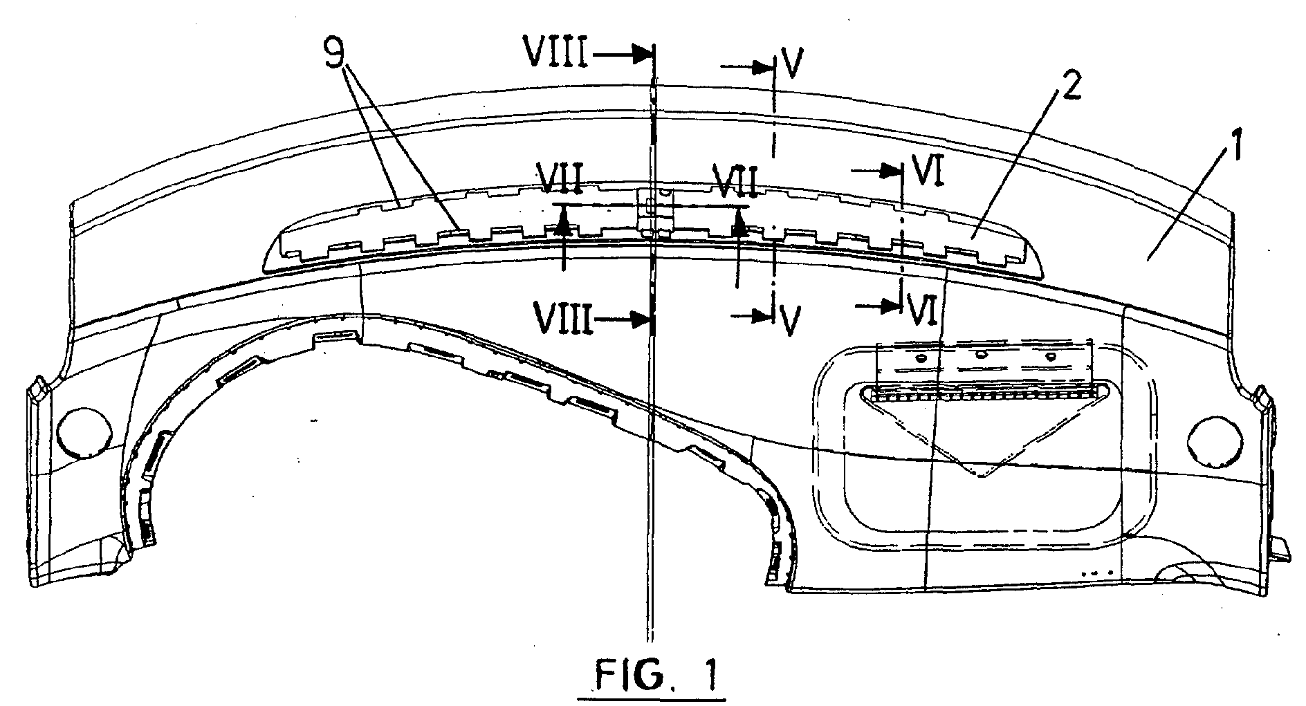
- Figure 1 shows a plan view of an automobile dashboard, labelled in general by the number 1, which is provided on its anterior area with a longitudinal opening 2 for air passage in which is mounted a grille meant to direct the air towards the windshield, for internal de-fogging and external defrosting when required.
- the grille is sub-divided into two identical independent bodies, each of which is slightly shorter in length than half the length of the opening 2. These two bodies are shown in figures 2 to 4, where they are labelled with the numbers 3 and 4. Each of these bodies consists of two longitudinal walls 5, an intermediate transverse partition 6 and transverse partitions 7, with the longitudinal walls 5 being joined on their ends by transverse closure walls, together defining a contour which ends on the top with a peripheral wing 8.
- the opening 2 as can be better seen in figure 1, is provided on its longitudinal edges with internal protrusions 9 that define a crenellated contour.
- each of the bodies 3 and 4 that define the grille is externally provided on its longitudinal walls 5 with shoes 10 that are located and sized such that they can be inserted in the separation between consecutive protrusions 9 of the opening 2.
- these shoes 10 are separated from the upper wing 8 of the bodies 3 and 4 by a distance that is approximately equal to the height of the protrusions 9.
- the shoes 10 have a sloping upper profile 11, with a downward inclination towards the external end of the grille body.
- the protrusions 9 of the opening 2 and the shoes 10 of the grille bodies 3 and 4 are located and sized such that said shoes can be inserted in a downwards sense between each two consecutive protrusions 9 and then displaced until they are located under said protrusions, in order to act as retaining means to prevent an accidental detachment of the grille bodies.
- the bodies 3 and 4 of the shoes are provided on their external ends with tabs 12 which are inserted through housings established in the ends of the opening 2.
- the bodies 3 and 4 are also provided with axial tabs or tongues 13 and 14, the first of which is provided with an orifice 15 and the second with a longitudinal groove 16 that begins at its free transverse edge, with said groove and orifice being superposed and opposite each other, as shown in figure 7, in order to receive a locking pin 17.
- an intermediate empty space is left which is closed by a core or cover 18, figure 8.
- the pin 17 can be locked by a retaining element 19 which prevents its accidental exit.
- the bodies 3 and 4 that form the grille are easily mounted by inserting the shoes 10 between each two consecutive protrusions 9 of the opening 2.
- the wing 8 of the bodies 3 and 4 rests on the surface of the dashboard 1, the said bodies will be longitudinally displaced towards the outside in opposite senses.
- the end tabs 12 are inserted in housings provided for such purpose, while the internal tongues 13 and 14 are superposed to receive the locking pin 17.
- the core or cover 18 is fitted, closing the separation between the bodies 3 and 4 and thereby completing the assembly of the grille.
- the walls and partitions of the bodies 3 and 4 of the grille shall have an inclination such that they direct the air flow suitably towards the windshield surface.
Abstract
Description
- The present invention relates to an automobile dashboard with an air orientation grille for defogging the windshield.
- More specifically, the dashboard of the invention is of the type that is provided on the top of its anterior area with a longitudinal opening for air passage, with a small width compared to its length, in which is mounted a grille meant to direct the air towards the surface of the windshield for de-fogging it.
- Low temperatures cause external frosting and internal fogging of automobile windshields. Dashboards have conducts for directing hot air towards said areas through a grille located on the top of the dashboard, facing the windshield. Normally, the various parts comprising these grilles are joined to each other and to the dashboards by welding or mechanical means, in any case such that disassembling the grilles for their replacement or repair when needed is prevented or hindered.
- The object of the present invention is to eliminate the aforementioned drawbacks by a dashboard of the type described above in which the orientation grille is constructed so that it allows its assembly and disassembly in a quick and simple manner, thereby simplifying these operations as well as reducing the cost of the assembly compared to conventional systems.
- In the dashboard of the invention the assembly and attachment of the orientation grilles does not require welding operations nor additional mechanical components. In the dashboard of the invention the orientation grilles are mounted by a "bayonet" type union, with the grille components sliding in two directions, first being displaced along the Z-axis direction and then along the Y-axis direction.
- According to the present invention, the opening of the dashboard in which the grille is mounted is provided on its longitudinal edges with internal protrusions that define a crenellated contour.
- On its part, the orientation grille is transversally sub-divided into two identical and independent bodies, each of which is slightly shorter in length than half the length of the opening. Each of these bodies is limited by a wall that determines its contour and which is crossed by internal partitions. Extending outwards from the longitudinal surfaces of the wall are shoes which are located and sized such that they can be inserted by sliding vertically in the separation between consecutive protrusions of the dashboard opening. In addition, the shoes are distanced from the top edge of bodies by a length that is approximately twice the height of the protrusions of the opening. The shoes determine a sloping upper profile, with a downwards inclination towards the external end of the grille.
- With the described construction the aforementioned protrusions and shoes are located and configured such that the shoes, after being inserted between the protrusions, can slide under said protrusions when the grilles are displaced longitudinally in opposite senses towards the external ends of the opening. When the two grille bodies reach the external end position a separation is established between them that will be closed by a central core.
- The two bodies that form the grille are also provided on their ends with anchoring means. These means can consist in the external ends of tabs or tongues which are inserted in opposing housings conformed in the transverse ends of the dashboard opening, while on the internal adjacent ends the means consist of tabs which can be superposed and anchored to each other.
- In order to aid a better understanding of the assembly and anchoring system for the orientation grilles in the dashboard of the invention, a more detailed description is provided below made with reference to the accompanying drawings where a non-limiting example of an embodiment is shown.
- In the drawings:
- Figure 1 is a plan view of a dashboard made according to the invention.
- Figure 2 is an upper plan view of the orientation grille mounted in the opening of the dashboard of figure 1.
- Figures 3 and 4 are perspective views of the left and right bodies of the grille of figure 2.
- Figures 5 and 6 are cross sections of the dashboard opening, with the grille mounted, respectively along the lines V-V and VI-VI.
- Figures 7 and 8 are longitudinal and cross sections of the dashboard opening, with the grille mounted, respectively along the lines VII-VII and VIII-VIII of figure 1.
-
- Figure 1 shows a plan view of an automobile dashboard, labelled in general by the number 1, which is provided on its anterior area with a
longitudinal opening 2 for air passage in which is mounted a grille meant to direct the air towards the windshield, for internal de-fogging and external defrosting when required. - According to the present invention the grille is sub-divided into two identical independent bodies, each of which is slightly shorter in length than half the length of the
opening 2. These two bodies are shown in figures 2 to 4, where they are labelled with thenumbers 3 and 4. Each of these bodies consists of twolongitudinal walls 5, an intermediatetransverse partition 6 and transverse partitions 7, with thelongitudinal walls 5 being joined on their ends by transverse closure walls, together defining a contour which ends on the top with a peripheral wing 8. - The
opening 2, as can be better seen in figure 1, is provided on its longitudinal edges with internal protrusions 9 that define a crenellated contour. - On their part, each of the
bodies 3 and 4 that define the grille is externally provided on itslongitudinal walls 5 withshoes 10 that are located and sized such that they can be inserted in the separation between consecutive protrusions 9 of theopening 2. In addition, theseshoes 10 are separated from the upper wing 8 of thebodies 3 and 4 by a distance that is approximately equal to the height of the protrusions 9. - As can be better seen in figures 3 and 4, the
shoes 10 have a slopingupper profile 11, with a downward inclination towards the external end of the grille body. - With the described construction, the protrusions 9 of the
opening 2 and theshoes 10 of thegrille bodies 3 and 4 are located and sized such that said shoes can be inserted in a downwards sense between each two consecutive protrusions 9 and then displaced until they are located under said protrusions, in order to act as retaining means to prevent an accidental detachment of the grille bodies. - When the
grille bodies 3 and 4 are inserted in theopening 2, with theshoes 10 passing between each two consecutive protrusions 9 of said opening, the upper wing 8 of said bodies rests on the dashboard 1, as shown in figure 5. When thebodies 3 and 4 slide outward, when reaching their end position, theshoes 10 are located under the protrusions 9 as shown in figure 6. - The
bodies 3 and 4 of the shoes are provided on their external ends withtabs 12 which are inserted through housings established in the ends of theopening 2. At the adjacent internal ends thebodies 3 and 4 are also provided with axial tabs ortongues orifice 15 and the second with alongitudinal groove 16 that begins at its free transverse edge, with said groove and orifice being superposed and opposite each other, as shown in figure 7, in order to receive alocking pin 17. In this position, between thebodies 3 and 4 an intermediate empty space is left which is closed by a core orcover 18, figure 8. Thepin 17 can be locked by aretaining element 19 which prevents its accidental exit. - With the described construction, the
bodies 3 and 4 that form the grille are easily mounted by inserting theshoes 10 between each two consecutive protrusions 9 of theopening 2. When the wing 8 of thebodies 3 and 4 rests on the surface of the dashboard 1, the said bodies will be longitudinally displaced towards the outside in opposite senses. When they reach the end position, theend tabs 12 are inserted in housings provided for such purpose, while theinternal tongues locking pin 17. Then the core orcover 18 is fitted, closing the separation between thebodies 3 and 4 and thereby completing the assembly of the grille. - If the grille must be disassembled, it is only necessary to remove the core or cover 18, extract the
pin 17 and then move thebodies 3 and 4 towards the centre and extract them upwards. - The walls and partitions of the
bodies 3 and 4 of the grille shall have an inclination such that they direct the air flow suitably towards the windshield surface.
Claims (2)
- Automobile dashboard comprising a longitudinal opening (2) for air passage with a small width with respect to its length, in which is mounted an orientation grille with an identical contour meant to direct the air towards the surface of the windshield, characterised in that the opening is provided in its longitudinal edges with internal protrusions that define a crenellated contour; and in that the grille is transversally sub-divided into two independent identical bodies (3, 4), each of which is shorter in length than half the length of the opening and is externally provided with shoes (10) that project out of the longitudinal surfaces, located and sized such that they can be inserted in the separation between consecutive protrusions (9) of the dashboard opening and set at a distance from the upper edge that is equal to the height of said protrusions, said shoes having a sloping upper profile (11) inclined downwards toward the external end of the grille body, with the aforementioned protrusions and shoes located such that once the shoes (10) have been inserted between the protrusions (9) they can move beneath said protrusions when displacing longitudinally the two grille bodies towards the ends of the opening, determining an intermediate separation that is closed by a central core; the two grille bodies further being provided with anchoring means on their ends.
- Dashboard according to claim 1, characterised in that the anchoring means on the ends of the grille bodies consist of tabs (12) which project out of the external ends, meant to be inserted in housings provided in the dashboard opening, and axial tabs or tongues (13, 14) which project out of the internal end and are superposed to receive a locking pin or screw.
Applications Claiming Priority (2)
| Application Number | Priority Date | Filing Date | Title |
|---|---|---|---|
| ES200200716U ES1051457Y (en) | 2002-03-22 | 2002-03-22 | INSTRUMENT BOARD FOR MOTOR VEHICLE. |
| ES200200716 | 2002-03-26 |
Publications (3)
| Publication Number | Publication Date |
|---|---|
| EP1346860A2 true EP1346860A2 (en) | 2003-09-24 |
| EP1346860A3 EP1346860A3 (en) | 2004-02-11 |
| EP1346860B1 EP1346860B1 (en) | 2005-06-15 |
Family
ID=8500779
Family Applications (1)
| Application Number | Title | Priority Date | Filing Date |
|---|---|---|---|
| EP02380254A Expired - Lifetime EP1346860B1 (en) | 2002-03-22 | 2002-12-10 | Automobile Dashboard with a two-parts air grille |
Country Status (4)
| Country | Link |
|---|---|
| EP (1) | EP1346860B1 (en) |
| AT (1) | ATE297846T1 (en) |
| DE (1) | DE60204654T2 (en) |
| ES (2) | ES1051457Y (en) |
Cited By (1)
| Publication number | Priority date | Publication date | Assignee | Title |
|---|---|---|---|---|
| FR2891201A3 (en) * | 2005-09-27 | 2007-03-30 | Renault Sas | Grille for air ducts in cars has sloping bores linking its rear surface and its front surface which direct air to position in front of and above head of passenger |
Citations (1)
| Publication number | Priority date | Publication date | Assignee | Title |
|---|---|---|---|---|
| US5762395A (en) * | 1996-06-25 | 1998-06-09 | General Motors Corporation | Molded cross car support structure |
-
2002
- 2002-03-22 ES ES200200716U patent/ES1051457Y/en not_active Expired - Fee Related
- 2002-12-10 ES ES02380254T patent/ES2243677T3/en not_active Expired - Lifetime
- 2002-12-10 EP EP02380254A patent/EP1346860B1/en not_active Expired - Lifetime
- 2002-12-10 DE DE60204654T patent/DE60204654T2/en not_active Expired - Lifetime
- 2002-12-10 AT AT02380254T patent/ATE297846T1/en not_active IP Right Cessation
Patent Citations (1)
| Publication number | Priority date | Publication date | Assignee | Title |
|---|---|---|---|---|
| US5762395A (en) * | 1996-06-25 | 1998-06-09 | General Motors Corporation | Molded cross car support structure |
Cited By (1)
| Publication number | Priority date | Publication date | Assignee | Title |
|---|---|---|---|---|
| FR2891201A3 (en) * | 2005-09-27 | 2007-03-30 | Renault Sas | Grille for air ducts in cars has sloping bores linking its rear surface and its front surface which direct air to position in front of and above head of passenger |
Also Published As
| Publication number | Publication date |
|---|---|
| EP1346860A3 (en) | 2004-02-11 |
| ATE297846T1 (en) | 2005-07-15 |
| ES1051457U (en) | 2002-08-01 |
| ES2243677T3 (en) | 2005-12-01 |
| ES1051457Y (en) | 2002-11-16 |
| DE60204654T2 (en) | 2006-05-11 |
| EP1346860B1 (en) | 2005-06-15 |
| DE60204654D1 (en) | 2005-07-21 |
Similar Documents
| Publication | Publication Date | Title |
|---|---|---|
| US6202741B1 (en) | Heat transfer device for a motor vehicle and method of making same | |
| US8398161B2 (en) | Sunroof headliner attachment system | |
| US20060196205A1 (en) | Air conditioning unit | |
| ES2354186T3 (en) | CLIMATE CONTROL DEVICE OF A VEHICLE THAT INCLUDES A NETWORK OF DEFROSTING BEHAVIORS. | |
| JP4744061B2 (en) | Heating and / or air conditioning equipment for commercial vehicles, eg buses | |
| US7118154B2 (en) | Structure for supporting an instrument panel by a defroster nozzle | |
| US4601510A (en) | Front body structure for motor vehicle | |
| US6364388B1 (en) | Air return bulkhead for use with a transport temperature control system | |
| EP1346860B1 (en) | Automobile Dashboard with a two-parts air grille | |
| US4560186A (en) | Connecting pin configuration | |
| US20040203333A1 (en) | Defroster device for a vehicle | |
| CN105073460A (en) | Air-conditioning device for vehicle | |
| US8795042B2 (en) | Defroster nozzle | |
| CN108454709B (en) | Rear wheel case ventilation assembly and vehicle | |
| JPH0410137Y2 (en) | ||
| US20060284446A1 (en) | Assembly of automobile body elements and method of mounting the assembly | |
| ES2326805T3 (en) | ANGLE ACCESSORY FOR CHANNELS THAT INCLUDES TWO FINS ASSEMBLED TO THE BIES. | |
| US20070137832A1 (en) | Component for a device for air-conditioning the inside of a vehicle and device for air-conditioning the inside of a vehicle | |
| EP3078518B1 (en) | Vehicle air-conditioning apparatus | |
| EP0989005B1 (en) | Defroster duct installation structure | |
| ITRM20000013A1 (en) | VEHICLE VENTILATION DEVICE. | |
| EP1518754B1 (en) | Outside light indicator for a third brake light on automotive vehicles | |
| CA2297703C (en) | Air intake manifold for a vehicle ventilation system | |
| US6092385A (en) | Cooling unit for vehicle air conditioner | |
| JPH11348602A (en) | Defroster structure for instrument panel |
Legal Events
| Date | Code | Title | Description |
|---|---|---|---|
| PUAI | Public reference made under article 153(3) epc to a published international application that has entered the european phase |
Free format text: ORIGINAL CODE: 0009012 |
|
| AK | Designated contracting states |
Kind code of ref document: A2 Designated state(s): AT BE BG CH CY CZ DE DK EE ES FI FR GB GR IE IT LI LU MC NL PT SE SI SK TR |
|
| AX | Request for extension of the european patent |
Extension state: AL LT LV MK RO |
|
| PUAL | Search report despatched |
Free format text: ORIGINAL CODE: 0009013 |
|
| AK | Designated contracting states |
Kind code of ref document: A3 Designated state(s): AT BE BG CH CY CZ DE DK EE ES FI FR GB GR IE IT LI LU MC NL PT SE SI SK TR |
|
| AX | Request for extension of the european patent |
Extension state: AL LT LV MK RO |
|
| RIC1 | Information provided on ipc code assigned before grant |
Ipc: 7B 62D 25/14 B Ipc: 7B 60H 1/00 B Ipc: 7B 60H 1/34 A Ipc: 7B 60K 37/04 B |
|
| 17P | Request for examination filed |
Effective date: 20040614 |
|
| AKX | Designation fees paid |
Designated state(s): AT BE BG CH CY CZ DE DK EE ES FI FR GB GR IE IT LI LU MC NL PT SE SI SK TR |
|
| GRAP | Despatch of communication of intention to grant a patent |
Free format text: ORIGINAL CODE: EPIDOSNIGR1 |
|
| GRAS | Grant fee paid |
Free format text: ORIGINAL CODE: EPIDOSNIGR3 |
|
| GRAA | (expected) grant |
Free format text: ORIGINAL CODE: 0009210 |
|
| AK | Designated contracting states |
Kind code of ref document: B1 Designated state(s): AT BE BG CH CY CZ DE DK EE ES FI FR GB GR IE IT LI LU MC NL PT SE SI SK TR |
|
| PG25 | Lapsed in a contracting state [announced via postgrant information from national office to epo] |
Ref country code: CH Free format text: LAPSE BECAUSE OF FAILURE TO SUBMIT A TRANSLATION OF THE DESCRIPTION OR TO PAY THE FEE WITHIN THE PRESCRIBED TIME-LIMIT Effective date: 20050615 Ref country code: SI Free format text: LAPSE BECAUSE OF FAILURE TO SUBMIT A TRANSLATION OF THE DESCRIPTION OR TO PAY THE FEE WITHIN THE PRESCRIBED TIME-LIMIT Effective date: 20050615 Ref country code: LI Free format text: LAPSE BECAUSE OF FAILURE TO SUBMIT A TRANSLATION OF THE DESCRIPTION OR TO PAY THE FEE WITHIN THE PRESCRIBED TIME-LIMIT Effective date: 20050615 Ref country code: TR Free format text: LAPSE BECAUSE OF FAILURE TO SUBMIT A TRANSLATION OF THE DESCRIPTION OR TO PAY THE FEE WITHIN THE PRESCRIBED TIME-LIMIT Effective date: 20050615 Ref country code: BE Free format text: LAPSE BECAUSE OF FAILURE TO SUBMIT A TRANSLATION OF THE DESCRIPTION OR TO PAY THE FEE WITHIN THE PRESCRIBED TIME-LIMIT Effective date: 20050615 Ref country code: AT Free format text: LAPSE BECAUSE OF FAILURE TO SUBMIT A TRANSLATION OF THE DESCRIPTION OR TO PAY THE FEE WITHIN THE PRESCRIBED TIME-LIMIT Effective date: 20050615 Ref country code: CZ Free format text: LAPSE BECAUSE OF FAILURE TO SUBMIT A TRANSLATION OF THE DESCRIPTION OR TO PAY THE FEE WITHIN THE PRESCRIBED TIME-LIMIT Effective date: 20050615 Ref country code: EE Free format text: LAPSE BECAUSE OF FAILURE TO SUBMIT A TRANSLATION OF THE DESCRIPTION OR TO PAY THE FEE WITHIN THE PRESCRIBED TIME-LIMIT Effective date: 20050615 Ref country code: NL Free format text: LAPSE BECAUSE OF FAILURE TO SUBMIT A TRANSLATION OF THE DESCRIPTION OR TO PAY THE FEE WITHIN THE PRESCRIBED TIME-LIMIT Effective date: 20050615 Ref country code: SK Free format text: LAPSE BECAUSE OF FAILURE TO SUBMIT A TRANSLATION OF THE DESCRIPTION OR TO PAY THE FEE WITHIN THE PRESCRIBED TIME-LIMIT Effective date: 20050615 Ref country code: FI Free format text: LAPSE BECAUSE OF FAILURE TO SUBMIT A TRANSLATION OF THE DESCRIPTION OR TO PAY THE FEE WITHIN THE PRESCRIBED TIME-LIMIT Effective date: 20050615 |
|
| REG | Reference to a national code |
Ref country code: CH Ref legal event code: EP Ref country code: GB Ref legal event code: FG4D |
|
| REF | Corresponds to: |
Ref document number: 60204654 Country of ref document: DE Date of ref document: 20050721 Kind code of ref document: P |
|
| REG | Reference to a national code |
Ref country code: IE Ref legal event code: FG4D |
|
| PG25 | Lapsed in a contracting state [announced via postgrant information from national office to epo] |
Ref country code: GR Free format text: LAPSE BECAUSE OF FAILURE TO SUBMIT A TRANSLATION OF THE DESCRIPTION OR TO PAY THE FEE WITHIN THE PRESCRIBED TIME-LIMIT Effective date: 20050915 Ref country code: DK Free format text: LAPSE BECAUSE OF FAILURE TO SUBMIT A TRANSLATION OF THE DESCRIPTION OR TO PAY THE FEE WITHIN THE PRESCRIBED TIME-LIMIT Effective date: 20050915 Ref country code: SE Free format text: LAPSE BECAUSE OF FAILURE TO SUBMIT A TRANSLATION OF THE DESCRIPTION OR TO PAY THE FEE WITHIN THE PRESCRIBED TIME-LIMIT Effective date: 20050915 Ref country code: BG Free format text: LAPSE BECAUSE OF FAILURE TO SUBMIT A TRANSLATION OF THE DESCRIPTION OR TO PAY THE FEE WITHIN THE PRESCRIBED TIME-LIMIT Effective date: 20050915 |
|
| PG25 | Lapsed in a contracting state [announced via postgrant information from national office to epo] |
Ref country code: PT Free format text: LAPSE BECAUSE OF FAILURE TO SUBMIT A TRANSLATION OF THE DESCRIPTION OR TO PAY THE FEE WITHIN THE PRESCRIBED TIME-LIMIT Effective date: 20051124 |
|
| NLV1 | Nl: lapsed or annulled due to failure to fulfill the requirements of art. 29p and 29m of the patents act | ||
| REG | Reference to a national code |
Ref country code: ES Ref legal event code: FG2A Ref document number: 2243677 Country of ref document: ES Kind code of ref document: T3 |
|
| PG25 | Lapsed in a contracting state [announced via postgrant information from national office to epo] |
Ref country code: CY Free format text: LAPSE BECAUSE OF FAILURE TO SUBMIT A TRANSLATION OF THE DESCRIPTION OR TO PAY THE FEE WITHIN THE PRESCRIBED TIME-LIMIT Effective date: 20051210 |
|
| PG25 | Lapsed in a contracting state [announced via postgrant information from national office to epo] |
Ref country code: IE Free format text: LAPSE BECAUSE OF NON-PAYMENT OF DUE FEES Effective date: 20051212 |
|
| REG | Reference to a national code |
Ref country code: CH Ref legal event code: PL |
|
| PG25 | Lapsed in a contracting state [announced via postgrant information from national office to epo] |
Ref country code: LU Free format text: LAPSE BECAUSE OF NON-PAYMENT OF DUE FEES Effective date: 20051231 Ref country code: MC Free format text: LAPSE BECAUSE OF NON-PAYMENT OF DUE FEES Effective date: 20051231 |
|
| ET | Fr: translation filed | ||
| PLBE | No opposition filed within time limit |
Free format text: ORIGINAL CODE: 0009261 |
|
| STAA | Information on the status of an ep patent application or granted ep patent |
Free format text: STATUS: NO OPPOSITION FILED WITHIN TIME LIMIT |
|
| 26N | No opposition filed |
Effective date: 20060316 |
|
| REG | Reference to a national code |
Ref country code: IE Ref legal event code: MM4A |
|
| PGFP | Annual fee paid to national office [announced via postgrant information from national office to epo] |
Ref country code: DE Payment date: 20120103 Year of fee payment: 10 |
|
| PGFP | Annual fee paid to national office [announced via postgrant information from national office to epo] |
Ref country code: IT Payment date: 20121220 Year of fee payment: 11 |
|
| PGFP | Annual fee paid to national office [announced via postgrant information from national office to epo] |
Ref country code: GB Payment date: 20130102 Year of fee payment: 11 Ref country code: FR Payment date: 20130121 Year of fee payment: 11 Ref country code: ES Payment date: 20130125 Year of fee payment: 11 |
|
| REG | Reference to a national code |
Ref country code: DE Ref legal event code: R119 Ref document number: 60204654 Country of ref document: DE Effective date: 20130702 |
|
| PG25 | Lapsed in a contracting state [announced via postgrant information from national office to epo] |
Ref country code: DE Free format text: LAPSE BECAUSE OF NON-PAYMENT OF DUE FEES Effective date: 20130702 |
|
| GBPC | Gb: european patent ceased through non-payment of renewal fee |
Effective date: 20131210 |
|
| REG | Reference to a national code |
Ref country code: FR Ref legal event code: ST Effective date: 20140829 |
|
| PG25 | Lapsed in a contracting state [announced via postgrant information from national office to epo] |
Ref country code: FR Free format text: LAPSE BECAUSE OF NON-PAYMENT OF DUE FEES Effective date: 20131231 Ref country code: GB Free format text: LAPSE BECAUSE OF NON-PAYMENT OF DUE FEES Effective date: 20131210 |
|
| REG | Reference to a national code |
Ref country code: ES Ref legal event code: FD2A Effective date: 20150506 |
|
| PG25 | Lapsed in a contracting state [announced via postgrant information from national office to epo] |
Ref country code: ES Free format text: LAPSE BECAUSE OF NON-PAYMENT OF DUE FEES Effective date: 20131211 |
|
| PG25 | Lapsed in a contracting state [announced via postgrant information from national office to epo] |
Ref country code: IT Free format text: LAPSE BECAUSE OF NON-PAYMENT OF DUE FEES Effective date: 20131231 |
|
| PG25 | Lapsed in a contracting state [announced via postgrant information from national office to epo] |
Ref country code: IT Free format text: LAPSE BECAUSE OF NON-PAYMENT OF DUE FEES Effective date: 20131210 |