EP1346385B1 - Automatic current limiting circuit breaker - Google Patents
Automatic current limiting circuit breaker Download PDFInfo
- Publication number
- EP1346385B1 EP1346385B1 EP01272646A EP01272646A EP1346385B1 EP 1346385 B1 EP1346385 B1 EP 1346385B1 EP 01272646 A EP01272646 A EP 01272646A EP 01272646 A EP01272646 A EP 01272646A EP 1346385 B1 EP1346385 B1 EP 1346385B1
- Authority
- EP
- European Patent Office
- Prior art keywords
- contact
- movable contact
- circuit breaker
- current limiting
- fixed
- Prior art date
- Legal status (The legal status is an assumption and is not a legal conclusion. Google has not performed a legal analysis and makes no representation as to the accuracy of the status listed.)
- Expired - Lifetime
Links
Images


Classifications
-
- H—ELECTRICITY
- H01—ELECTRIC ELEMENTS
- H01H—ELECTRIC SWITCHES; RELAYS; SELECTORS; EMERGENCY PROTECTIVE DEVICES
- H01H73/00—Protective overload circuit-breaking switches in which excess current opens the contacts by automatic release of mechanical energy stored by previous operation of a hand reset mechanism
- H01H73/02—Details
- H01H73/04—Contacts
- H01H73/045—Bridging contacts
-
- H—ELECTRICITY
- H01—ELECTRIC ELEMENTS
- H01H—ELECTRIC SWITCHES; RELAYS; SELECTORS; EMERGENCY PROTECTIVE DEVICES
- H01H1/00—Contacts
- H01H1/12—Contacts characterised by the manner in which co-operating contacts engage
- H01H1/14—Contacts characterised by the manner in which co-operating contacts engage by abutting
- H01H1/20—Bridging contacts
- H01H2001/2091—Bridging contacts having two pivotally and electrically connected halve bridges
-
- H—ELECTRICITY
- H01—ELECTRIC ELEMENTS
- H01H—ELECTRIC SWITCHES; RELAYS; SELECTORS; EMERGENCY PROTECTIVE DEVICES
- H01H77/00—Protective overload circuit-breaking switches operated by excess current and requiring separate action for resetting
- H01H77/02—Protective overload circuit-breaking switches operated by excess current and requiring separate action for resetting in which the excess current itself provides the energy for opening the contacts, and having a separate reset mechanism
- H01H77/10—Protective overload circuit-breaking switches operated by excess current and requiring separate action for resetting in which the excess current itself provides the energy for opening the contacts, and having a separate reset mechanism with electrodynamic opening
- H01H77/102—Protective overload circuit-breaking switches operated by excess current and requiring separate action for resetting in which the excess current itself provides the energy for opening the contacts, and having a separate reset mechanism with electrodynamic opening characterised by special mounting of contact arm, allowing blow-off movement
- H01H77/104—Protective overload circuit-breaking switches operated by excess current and requiring separate action for resetting in which the excess current itself provides the energy for opening the contacts, and having a separate reset mechanism with electrodynamic opening characterised by special mounting of contact arm, allowing blow-off movement with a stable blow-off position
Definitions
- the present invention relates to a circuit breaker and particularly to an automatic current limiting circuit breaker that has a system with double interruption in series with at least two arc quenching chambers for each pole.
- Low-voltage electrical systems characterized by high currents and power levels normally use specific devices provided with a system that ensures the nominal current required for the various users, the insertion and disconnection of the load, the protection of the loads against abnormal events such as overloading and short-circuits by automatically opening the circuit, and finally the disconnection of the protected circuit by opening the movable contacts with respect to the fixed contacts in order to achieve full isolation of the load with respect to the electric power source.
- These devices are commonly known as automatic power switches for use in low-voltage industrial systems.
- each pole is interrupted in two separate regions that are electrically in series to each other, so that each one is subjected to less mechanical and thermal stress.
- the second solution is based on a reduction of the tripping time, so as to prevent the presumed short-circuit current from reaching its maximum value.
- the aim of the present invention is to provide an automatic current limiting circuit breaker whose mechanism and operating principle are simplified with respect to the circuit breakers of the known art.
- Document FR 2 373 143 discloses a device according to the preamble of claim 1.
- an object of the present invention is to provide an automatic current limiting circuit breaker that improves the distribution of the mechanical loads supported by the movable contacts.
- Another object is to provide an automatic current limiting circuit breaker in which energy dissipation due to the Joule effect is minimized.
- Another object is to provide an automatic current limiting circuit breaker that has reduced overall dimensions for an equal electrical performance and expected life.
- Another object of the present invention is to provide an automatic current limiting circuit breaker that is highly reliable, relatively easy to provide and at competitive costs.
- an automatic current limiting circuit breaker which comprises an insulating enclosure that accommodates fixed contact means and movable contact means, actuation means for actuating said movable contact means between open-circuit conditions and closed-circuit conditions, and arc quenching means that comprise at least one first and one second arc quenching chamber which are mutually separate
- the fixed contact means comprising at least one first and one second fixed contact, which are mutually spaced and positioned respectively adjacent to the first and second arc quenching chambers
- the movable contact means comprising at least one first movable contact and one second movable contact, which are electrically series-connected and can move simultaneously between open-circuit and closed-circuit positions
- the movable contact means comprise a first contact arm and a second contact arm that have a first end at which the first movable contact and the second movable contact are respectively fixed and a second end that is fixed on, and free to rotate about, a common pivot that
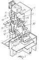
- the automatic current limiting circuit breaker comprises an insulating enclosure 1, of which only a cutout view is shown.
- the enclosure 1 accommodates fixed contact means, generally designated by the reference numeral 10, and movable contact means, generally designated by the reference numeral 20.
- the circuit breaker also comprises actuation means for moving the movable contact means between an open-circuit condition (shown in dashed lines in Figures 3 and 4) and a closed-circuit condition.
- a detail of the actuation means is given in Figures 1 and 4, which show an example of kinematic actuation chain 30.
- the circuit breaker further comprises arc quenching means, constituted by two mutually separate arc quenching chambers; the arc quenching chambers are not shown in the figures for the sake of clarity.
- Figure 1 shows the seats 2 and 3 formed in the enclosure 1 and suitable to accommodate said arc quenching chambers.
- the fixed contact means 10 comprise a first fixed contact 11 and a second fixed contact 12, which are mutually spaced and arranged respectively adjacent to the first and second arc quenching chambers, at the seats 2 and 3.
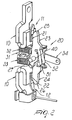
- the movable contact means 20 comprise a first movable contact 21 and a second movable contact 22, which are electrically series-connected and can be moved simultaneously between open-circuit and closed-circuit positions.
- the movable contact means 20 furthermore comprise a first contact arm 23 and a second contact arm 24, which are constituted by two elongated conducting plates that have a first end, designated by the reference numerals 25 and 26 respectively, at which the first movable contact 21 and the second movable contact 22 are fixed.
- the second end which is designated by the reference numeral 27 for the first movable arm 23, whereas the end of the second movable arm 24 is not visible, is fixed to a common pivot 40 so that the two movable arms 23 and 24 are free to rotate about it.
- the common pivot 40 is therefore operatively connected to the actuation means in order to allow the movement of the movable contacts.
- the first and second contact arms 23 and 24 are mutually electrically series-connected by virtue of at least one flexible conductor.
- the electrical series connection can be provided by means of a pair of copper braids 51 and 52.
- the common pivot 40 is fixed to a plate 31 that is operatively connected to the actuation means.
- the plate 31 can slide freely in an appropriate space formed between the seats 2 and 3 of the arc quenching chambers.
- the first and second contact arms 23 and 24 are preferably operatively associated with elastic means that perform this function.
- the elastic means can be constituted for example by two springs 32 and 33 that are respectively associated with the first and second contact arms 23 and 24, for example proximate to their end that lies opposite the movable contact 20.
- connection of the movable contact parts to the actuation means can be performed for example by means of a coupling lever 34, one end of which is rigidly coupled to the pivot 40 while the other end is rigidly coupled to the kinematic chain 30.
- the reduced complexity of the kinematic system allows to reduce the overall space occupation of the units for an equal electrical performance and expected life.
Abstract
Description
- The present invention relates to a circuit breaker and particularly to an automatic current limiting circuit breaker that has a system with double interruption in series with at least two arc quenching chambers for each pole.
- Low-voltage electrical systems characterized by high currents and power levels normally use specific devices provided with a system that ensures the nominal current required for the various users, the insertion and disconnection of the load, the protection of the loads against abnormal events such as overloading and short-circuits by automatically opening the circuit, and finally the disconnection of the protected circuit by opening the movable contacts with respect to the fixed contacts in order to achieve full isolation of the load with respect to the electric power source. These devices are commonly known as automatic power switches for use in low-voltage industrial systems.
- There are several industrial solutions for these devices. The most common solution entrusts the opening of the contacts to complex mechanisms actuated by the mechanical energy accumulated beforehand in special springs.
- If the presumed level of short-circuit current is particularly high, the energy that can be accumulated in the springs may be insufficient for effective contact opening. In such cases one normally uses special types of automatic circuit breaker provided with technical solutions aimed at increasing the breaking capacity.
- Among the most valid solutions there are two in particular that are often used together.
- The first of these solutions entails doubling the contacts. In this case, each pole is interrupted in two separate regions that are electrically in series to each other, so that each one is subjected to less mechanical and thermal stress.
- The second solution is based on a reduction of the tripping time, so as to prevent the presumed short-circuit current from reaching its maximum value.
- This is a solution that requires the path of the current to have a shape that triggers, in case of a short circuit, an electrodynamic phenomenon capable of positively contributing to the production of the mechanical thrust required to open the contacts. In some cases, the energy required is in fact several hundred newtons per meter.
- These solutions are often associated in so-called limiting circuit breakers, which as is known have, in principle, good efficiency and reliability but have some typical situations that involve compromise or criticality.
- It is in fact known that duplicating the interruption elements entails a considerable increase in the dimensions of the apparatus. It is also necessary to electrically connect in series the two movable contacts of each pole by virtue of copper braids which, since they have to be flexible and therefore relatively thin, inevitably introduce high energy losses due to the Joule effect.
- Moreover, there is the risk of an imperfect distribution of the mechanical loads supported by the movable contacts, with consequent repercussions on the electrical conductivity of the circuit breaker. This phenomenon can worsen during the life cycle of the unit, since it is linked to the constant but irregular wear of the plates located on the regions where the movable contacts encounter the fixed contacts.
- The aim of the present invention is to provide an automatic current limiting circuit breaker whose mechanism and operating principle are simplified with respect to the circuit breakers of the known art.
Document FR 2 373 143 - Within the scope of this aim, an object of the present invention is to provide an automatic current limiting circuit breaker that improves the distribution of the mechanical loads supported by the movable contacts.
- Another object is to provide an automatic current limiting circuit breaker in which energy dissipation due to the Joule effect is minimized.
- Another object is to provide an automatic current limiting circuit breaker that has reduced overall dimensions for an equal electrical performance and expected life.
- Another object of the present invention is to provide an automatic current limiting circuit breaker that is highly reliable, relatively easy to provide and at competitive costs.
- This aim these and other objects that will become better apparent hereinafter are achieved by an automatic current limiting circuit breaker, which comprises an insulating enclosure that accommodates fixed contact means and movable contact means, actuation means for actuating said movable contact means between open-circuit conditions and closed-circuit conditions, and arc quenching means that comprise at least one first and one second arc quenching chamber which are mutually separate, the fixed contact means comprising at least one first and one second fixed contact, which are mutually spaced and positioned respectively adjacent to the first and second arc quenching chambers, the movable contact means comprising at least one first movable contact and one second movable contact, which are electrically series-connected and can move simultaneously between open-circuit and closed-circuit positions, characterized in that the movable contact means comprise a first contact arm and a second contact arm that have a first end at which the first movable contact and the second movable contact are respectively fixed and a second end that is fixed on, and free to rotate about, a common pivot that is operatively connected to said actuation means.
- In this manner, in practice one provides an automatic current limiting circuit breaker that fully achieves the intended aim and objects. In particular, the specific configuration and operating principle of the movable contact means allows to reduce and simplify the number of parts required without altering the functional characteristics of said circuit breaker.
- Further characteristics and advantages will become better apparent from the description of preferred but not exclusive embodiments of the circuit breaker according to the invention, illustrated only by way of non-limitative example in the accompanying drawings, wherein:
- Figure 1 is a perspective view of an example of one of the poles of an automatic current limiting circuit breaker according to the invention;
- Figure 2 is a perspective view of details of a pole of an automatic current limiting circuit breaker according to the invention;
- Figure 3 is a partially sectional view of the same details of the pole of an automatic current limiting circuit breaker of Figure 2;
- Figure 4 is a partially sectional view of other details of a pole of an automatic current limiting circuit breaker according to the invention.
- With reference to the figures, the automatic current limiting circuit breaker according to the invention comprises an insulating enclosure 1, of which only a cutout view is shown. The enclosure 1 accommodates fixed contact means, generally designated by the
reference numeral 10, and movable contact means, generally designated by thereference numeral 20. The circuit breaker also comprises actuation means for moving the movable contact means between an open-circuit condition (shown in dashed lines in Figures 3 and 4) and a closed-circuit condition. A detail of the actuation means is given in Figures 1 and 4, which show an example ofkinematic actuation chain 30. - The circuit breaker further comprises arc quenching means, constituted by two mutually separate arc quenching chambers; the arc quenching chambers are not shown in the figures for the sake of clarity. However, Figure 1 shows the
seats - The fixed contact means 10 comprise a first fixed
contact 11 and a second fixedcontact 12, which are mutually spaced and arranged respectively adjacent to the first and second arc quenching chambers, at theseats - The movable contact means 20 comprise a first
movable contact 21 and a secondmovable contact 22, which are electrically series-connected and can be moved simultaneously between open-circuit and closed-circuit positions. As shown in Figure 2, the movable contact means 20 furthermore comprise afirst contact arm 23 and asecond contact arm 24, which are constituted by two elongated conducting plates that have a first end, designated by thereference numerals movable contact 21 and the secondmovable contact 22 are fixed. The second end, which is designated by thereference numeral 27 for the firstmovable arm 23, whereas the end of the secondmovable arm 24 is not visible, is fixed to acommon pivot 40 so that the twomovable arms common pivot 40 is therefore operatively connected to the actuation means in order to allow the movement of the movable contacts. - Advantageously, the first and
second contact arms copper braids - According to a preferred embodiment, the
common pivot 40 is fixed to aplate 31 that is operatively connected to the actuation means. Theplate 31 can slide freely in an appropriate space formed between theseats - As mentioned, it is important that the mechanical loads be distributed correctly between the movable contacts, also compensating for the wear that occurs over the life of the unit. For this purpose, the first and
second contact arms springs second contact arms movable contact 20. - The connection of the movable contact parts to the actuation means can be performed for example by means of a
coupling lever 34, one end of which is rigidly coupled to thepivot 40 while the other end is rigidly coupled to thekinematic chain 30. - In practice it has been found that the automatic current limiting circuit breaker according to the invention fully achieves the intended aim and objects. The advantages arising from the fact that the rotation axes of the two movable contacts are made to coincide, as a consequence of the common pivoting point of the contact arms, are in fact as follows.
- First of all, one has a better distribution of the mechanical loads supported by the movable contacts, with consequent benefits in terms of electrical conductivity of the circuit breaker and in terms of durability and stability of the kinematic system and therefore of the circuit breaker. The simplification of the kinematic mechanism that is based on setting the movable contacts about a common pivoting point in fact allows to continuously readapt and optimize the geometry of the coupling between the movable contacts and the fixed contacts, effectively compensating the effects of the normal progressive and independent wear of said contacts.
- Furthermore, the reduced complexity of the kinematic system allows to reduce the overall space occupation of the units for an equal electrical performance and expected life.
- One should not ignore the fact that by setting the movable contacts on a common pivoting point it is possible to reduce the length of the conductors, usually copper braids, that electrically connect to each other the pairs of movable contacts related to each pole; therefore the electrical resistance also decreases proportionally as said length decreases, consequently containing losses due to the Joule effect.
Claims (6)
- An automatic current limiting circuit breaker, comprising an insulating enclosure (1) that accommodates fixed contact means (10) and movable contact means (20), actuation means for actuating said movable contact means (20) between open-circuit conditions and closed-circuit conditions, and arc quenching means that comprise at least one first and one second arc quenching chamber which are mutually separate, the fixed contact means (10) comprising at least one first (11) and one second fixed contact (12), which are mutually spaced and positioned respectively adjacent to said first and second arc quenching chambers, the movable contact means (20) comprising at least one first movable contact (21) and one second movable contact (22), which are electrically series-connected and can move simultaneously between open-circuit and closed-circuit positions, whereby said movable contact means (20) comprise a first contact arm (23) and a second contact arm (24) that have a first end (25, 26) at which said first movable contact (21) and said second movable contact (22) are respectively fixed and a second end (27) that is fixed on, and free to rotate about, a common pivot (40) that is operatively connected to said actuation means (30), characterized in that said first contact arm (23) is operatively associated with first elastic means (32) and said second contact arm (24) is operatively associated with second elastic means (33).
- The automatic current limiting circuit breaker according to claim 1, characterized in that said first and second contact arms (23,24) are operatively associated with said first and second elastic means (32,33) proximate to one end that lies opposite to the corresponding said movable contact (21,22).
- The automatic current limiting circuit breaker, according to claim 1 or 2, characterized in that said first and second contact arms (23, 24) are mutually electrically series-connected by means of at least one flexible conductor.
- The automatic current limiting circuit breaker according to claim 3, characterized in that said first and second contact arms (23, 24) are mutually electrically series-connected by means of a pair of copper braids (51, 52).
- The automatic current limiting circuit breaker according to one or more of the preceding claims, characterized in that said common pivot (40) is fixed to a plate (31) that is operatively connected to said actuation means.
- The automatic current limiting circuit breaker according to one or more of the preceding claims, characterized in that said actuation means comprise a kinematic chain (30) and a coupling lever (34).
Applications Claiming Priority (3)
| Application Number | Priority Date | Filing Date | Title |
|---|---|---|---|
| ITMI20002875 | 2000-12-29 | ||
| IT2000MI002875A IT1319707B1 (en) | 2000-12-29 | 2000-12-29 | AUTOMATIC CURRENT LIMITER SWITCH |
| PCT/EP2001/014850 WO2002054431A1 (en) | 2000-12-29 | 2001-12-12 | Automatic current limiting circuit breaker |
Publications (2)
| Publication Number | Publication Date |
|---|---|
| EP1346385A1 EP1346385A1 (en) | 2003-09-24 |
| EP1346385B1 true EP1346385B1 (en) | 2007-06-20 |
Family
ID=11446371
Family Applications (1)
| Application Number | Title | Priority Date | Filing Date |
|---|---|---|---|
| EP01272646A Expired - Lifetime EP1346385B1 (en) | 2000-12-29 | 2001-12-12 | Automatic current limiting circuit breaker |
Country Status (7)
| Country | Link |
|---|---|
| EP (1) | EP1346385B1 (en) |
| CN (1) | CN1484846A (en) |
| AT (1) | ATE365373T1 (en) |
| DE (1) | DE60129041T2 (en) |
| ES (1) | ES2287075T3 (en) |
| IT (1) | IT1319707B1 (en) |
| WO (1) | WO2002054431A1 (en) |
Families Citing this family (2)
| Publication number | Priority date | Publication date | Assignee | Title |
|---|---|---|---|---|
| DE102011008831A1 (en) * | 2011-01-19 | 2012-07-19 | Abb Ag | Istallationsschaltgerät |
| CN102969210B (en) * | 2011-08-31 | 2017-06-09 | 首瑞(北京)投资管理集团有限公司 | Circuit breaker static contact |
Family Cites Families (2)
| Publication number | Priority date | Publication date | Assignee | Title |
|---|---|---|---|---|
| IT1006446B (en) * | 1974-04-12 | 1976-09-30 | Sace Spa | ELECTRIC CURRENT LIMITING SWITCH WITHOUT BOUNCES DURING OPENING |
| FR2373143A1 (en) * | 1976-12-06 | 1978-06-30 | Telemecanique Electrique | Electromagnetic switch with- two symmetrically pivoted arms - has arms integral with armature with spring transverse to movement of support |
-
2000
- 2000-12-29 IT IT2000MI002875A patent/IT1319707B1/en active
-
2001
- 2001-12-12 WO PCT/EP2001/014850 patent/WO2002054431A1/en active IP Right Grant
- 2001-12-12 DE DE60129041T patent/DE60129041T2/en not_active Expired - Lifetime
- 2001-12-12 AT AT01272646T patent/ATE365373T1/en not_active IP Right Cessation
- 2001-12-12 CN CNA018215440A patent/CN1484846A/en active Pending
- 2001-12-12 EP EP01272646A patent/EP1346385B1/en not_active Expired - Lifetime
- 2001-12-12 ES ES01272646T patent/ES2287075T3/en not_active Expired - Lifetime
Non-Patent Citations (1)
| Title |
|---|
| None * |
Also Published As
| Publication number | Publication date |
|---|---|
| DE60129041D1 (en) | 2007-08-02 |
| EP1346385A1 (en) | 2003-09-24 |
| DE60129041T2 (en) | 2008-02-21 |
| ATE365373T1 (en) | 2007-07-15 |
| IT1319707B1 (en) | 2003-11-03 |
| CN1484846A (en) | 2004-03-24 |
| ES2287075T3 (en) | 2007-12-16 |
| WO2002054431A1 (en) | 2002-07-11 |
| ITMI20002875A1 (en) | 2002-06-29 |
Similar Documents
| Publication | Publication Date | Title |
|---|---|---|
| CA2623847C (en) | Electrical switching apparatus, and conductor assembly and shunt assembly therefor | |
| EP0955658A2 (en) | Electrical switching apparatus with improved contact arm carrier arrangement | |
| CA2271247C (en) | Electrical switching apparatus having arc runner integral with stationary arcing contact | |
| EP1442466B1 (en) | Low-voltage circuit breaker | |
| US10748729B2 (en) | Low profile fusible disconnect switch device | |
| US6689979B1 (en) | Switching contact arrangement of a low voltage circuit breaker with main contacts, intermediate contact and arcing contacts | |
| EP0961306B1 (en) | Circuit braker provided with modular contact system for different frame sizes | |
| US9129768B2 (en) | Multipole electrical switching device | |
| CN111508784B (en) | Narrow-profile circuit breaker with arc extinguishing function | |
| EP1346385B1 (en) | Automatic current limiting circuit breaker | |
| EP2290667B1 (en) | Slide type movable contactor assembly for circuit breaker | |
| EP1218899B1 (en) | Electric pole for low-voltage power circuit breaker | |
| CA1331998C (en) | Circuit breaker with low voltage contact structure | |
| KR20210084627A (en) | Movable contact mechanism of double breakpoint breaker | |
| CN212392149U (en) | Breaking unit with electrodynamic force compensation and automatic dual-power transfer switch | |
| RU2795228C2 (en) | Low voltage circuit breaker | |
| US11804345B2 (en) | Low-voltage circuit breaker | |
| CN113838688A (en) | Breaking unit with electrodynamic force compensation and automatic dual-power transfer switch | |
| EP4330998A1 (en) | Slim circuit breaker | |
| RU10287U1 (en) | CIRCUIT BREAKER |
Legal Events
| Date | Code | Title | Description |
|---|---|---|---|
| PUAI | Public reference made under article 153(3) epc to a published international application that has entered the european phase |
Free format text: ORIGINAL CODE: 0009012 |
|
| 17P | Request for examination filed |
Effective date: 20030722 |
|
| AK | Designated contracting states |
Kind code of ref document: A1 Designated state(s): AT BE CH CY DE DK ES FI FR GB GR IE IT LI LU MC NL PT SE TR |
|
| AX | Request for extension of the european patent |
Extension state: AL LT LV MK RO SI |
|
| RAP1 | Party data changed (applicant data changed or rights of an application transferred) |
Owner name: ABB SERVICE S.R.L |
|
| GRAP | Despatch of communication of intention to grant a patent |
Free format text: ORIGINAL CODE: EPIDOSNIGR1 |
|
| GRAS | Grant fee paid |
Free format text: ORIGINAL CODE: EPIDOSNIGR3 |
|
| GRAA | (expected) grant |
Free format text: ORIGINAL CODE: 0009210 |
|
| AK | Designated contracting states |
Kind code of ref document: B1 Designated state(s): AT BE CH CY DE DK ES FI FR GB GR IE IT LI LU MC NL PT SE TR |
|
| PG25 | Lapsed in a contracting state [announced via postgrant information from national office to epo] |
Ref country code: LI Free format text: LAPSE BECAUSE OF FAILURE TO SUBMIT A TRANSLATION OF THE DESCRIPTION OR TO PAY THE FEE WITHIN THE PRESCRIBED TIME-LIMIT Effective date: 20070620 Ref country code: CH Free format text: LAPSE BECAUSE OF FAILURE TO SUBMIT A TRANSLATION OF THE DESCRIPTION OR TO PAY THE FEE WITHIN THE PRESCRIBED TIME-LIMIT Effective date: 20070620 |
|
| REG | Reference to a national code |
Ref country code: GB Ref legal event code: FG4D |
|
| REG | Reference to a national code |
Ref country code: CH Ref legal event code: EP |
|
| REG | Reference to a national code |
Ref country code: IE Ref legal event code: FG4D |
|
| REF | Corresponds to: |
Ref document number: 60129041 Country of ref document: DE Date of ref document: 20070802 Kind code of ref document: P |
|
| PG25 | Lapsed in a contracting state [announced via postgrant information from national office to epo] |
Ref country code: SE Free format text: LAPSE BECAUSE OF FAILURE TO SUBMIT A TRANSLATION OF THE DESCRIPTION OR TO PAY THE FEE WITHIN THE PRESCRIBED TIME-LIMIT Effective date: 20070920 |
|
| REG | Reference to a national code |
Ref country code: GR Ref legal event code: EP Ref document number: 20070402474 Country of ref document: GR |
|
| ET | Fr: translation filed | ||
| PG25 | Lapsed in a contracting state [announced via postgrant information from national office to epo] |
Ref country code: AT Free format text: LAPSE BECAUSE OF FAILURE TO SUBMIT A TRANSLATION OF THE DESCRIPTION OR TO PAY THE FEE WITHIN THE PRESCRIBED TIME-LIMIT Effective date: 20070620 |
|
| REG | Reference to a national code |
Ref country code: ES Ref legal event code: FG2A Ref document number: 2287075 Country of ref document: ES Kind code of ref document: T3 |
|
| REG | Reference to a national code |
Ref country code: CH Ref legal event code: PL |
|
| PG25 | Lapsed in a contracting state [announced via postgrant information from national office to epo] |
Ref country code: BE Free format text: LAPSE BECAUSE OF FAILURE TO SUBMIT A TRANSLATION OF THE DESCRIPTION OR TO PAY THE FEE WITHIN THE PRESCRIBED TIME-LIMIT Effective date: 20070620 |
|
| PG25 | Lapsed in a contracting state [announced via postgrant information from national office to epo] |
Ref country code: PT Free format text: LAPSE BECAUSE OF FAILURE TO SUBMIT A TRANSLATION OF THE DESCRIPTION OR TO PAY THE FEE WITHIN THE PRESCRIBED TIME-LIMIT Effective date: 20071120 |
|
| PLBE | No opposition filed within time limit |
Free format text: ORIGINAL CODE: 0009261 |
|
| STAA | Information on the status of an ep patent application or granted ep patent |
Free format text: STATUS: NO OPPOSITION FILED WITHIN TIME LIMIT |
|
| PG25 | Lapsed in a contracting state [announced via postgrant information from national office to epo] |
Ref country code: DK Free format text: LAPSE BECAUSE OF FAILURE TO SUBMIT A TRANSLATION OF THE DESCRIPTION OR TO PAY THE FEE WITHIN THE PRESCRIBED TIME-LIMIT Effective date: 20070620 |
|
| 26N | No opposition filed |
Effective date: 20080325 |
|
| PG25 | Lapsed in a contracting state [announced via postgrant information from national office to epo] |
Ref country code: MC Free format text: LAPSE BECAUSE OF NON-PAYMENT OF DUE FEES Effective date: 20071231 |
|
| PG25 | Lapsed in a contracting state [announced via postgrant information from national office to epo] |
Ref country code: IE Free format text: LAPSE BECAUSE OF NON-PAYMENT OF DUE FEES Effective date: 20071212 |
|
| PGFP | Annual fee paid to national office [announced via postgrant information from national office to epo] |
Ref country code: NL Payment date: 20081216 Year of fee payment: 8 |
|
| PG25 | Lapsed in a contracting state [announced via postgrant information from national office to epo] |
Ref country code: FI Free format text: LAPSE BECAUSE OF FAILURE TO SUBMIT A TRANSLATION OF THE DESCRIPTION OR TO PAY THE FEE WITHIN THE PRESCRIBED TIME-LIMIT Effective date: 20070620 |
|
| PGFP | Annual fee paid to national office [announced via postgrant information from national office to epo] |
Ref country code: GR Payment date: 20081218 Year of fee payment: 8 |
|
| PG25 | Lapsed in a contracting state [announced via postgrant information from national office to epo] |
Ref country code: CY Free format text: LAPSE BECAUSE OF FAILURE TO SUBMIT A TRANSLATION OF THE DESCRIPTION OR TO PAY THE FEE WITHIN THE PRESCRIBED TIME-LIMIT Effective date: 20070620 |
|
| PG25 | Lapsed in a contracting state [announced via postgrant information from national office to epo] |
Ref country code: LU Free format text: LAPSE BECAUSE OF NON-PAYMENT OF DUE FEES Effective date: 20071212 |
|
| PG25 | Lapsed in a contracting state [announced via postgrant information from national office to epo] |
Ref country code: TR Free format text: LAPSE BECAUSE OF FAILURE TO SUBMIT A TRANSLATION OF THE DESCRIPTION OR TO PAY THE FEE WITHIN THE PRESCRIBED TIME-LIMIT Effective date: 20070620 |
|
| REG | Reference to a national code |
Ref country code: FR Ref legal event code: TP |
|
| REG | Reference to a national code |
Ref country code: NL Ref legal event code: V1 Effective date: 20100701 |
|
| PG25 | Lapsed in a contracting state [announced via postgrant information from national office to epo] |
Ref country code: NL Free format text: LAPSE BECAUSE OF NON-PAYMENT OF DUE FEES Effective date: 20100701 |
|
| PGFP | Annual fee paid to national office [announced via postgrant information from national office to epo] |
Ref country code: ES Payment date: 20101223 Year of fee payment: 10 |
|
| REG | Reference to a national code |
Ref country code: ES Ref legal event code: FD2A Effective date: 20130703 |
|
| PG25 | Lapsed in a contracting state [announced via postgrant information from national office to epo] |
Ref country code: ES Free format text: LAPSE BECAUSE OF NON-PAYMENT OF DUE FEES Effective date: 20111213 |
|
| PGFP | Annual fee paid to national office [announced via postgrant information from national office to epo] |
Ref country code: GB Payment date: 20141219 Year of fee payment: 14 Ref country code: DE Payment date: 20141211 Year of fee payment: 14 |
|
| PGFP | Annual fee paid to national office [announced via postgrant information from national office to epo] |
Ref country code: FR Payment date: 20141219 Year of fee payment: 14 |
|
| REG | Reference to a national code |
Ref country code: DE Ref legal event code: R119 Ref document number: 60129041 Country of ref document: DE |
|
| GBPC | Gb: european patent ceased through non-payment of renewal fee |
Effective date: 20151212 |
|
| REG | Reference to a national code |
Ref country code: FR Ref legal event code: ST Effective date: 20160831 |
|
| PG25 | Lapsed in a contracting state [announced via postgrant information from national office to epo] |
Ref country code: GB Free format text: LAPSE BECAUSE OF NON-PAYMENT OF DUE FEES Effective date: 20151212 Ref country code: DE Free format text: LAPSE BECAUSE OF NON-PAYMENT OF DUE FEES Effective date: 20160701 |
|
| PG25 | Lapsed in a contracting state [announced via postgrant information from national office to epo] |
Ref country code: FR Free format text: LAPSE BECAUSE OF NON-PAYMENT OF DUE FEES Effective date: 20151231 |
|
| PGFP | Annual fee paid to national office [announced via postgrant information from national office to epo] |
Ref country code: IT Payment date: 20181220 Year of fee payment: 18 |
|
| PG25 | Lapsed in a contracting state [announced via postgrant information from national office to epo] |
Ref country code: IT Free format text: LAPSE BECAUSE OF NON-PAYMENT OF DUE FEES Effective date: 20191212 |