EP1346263B1 - Dispositif pour le montage d'un brin souple notamment sur une boite de montre et procede de montage d'un tel brin souple - Google Patents
Dispositif pour le montage d'un brin souple notamment sur une boite de montre et procede de montage d'un tel brin souple Download PDFInfo
- Publication number
- EP1346263B1 EP1346263B1 EP01271981A EP01271981A EP1346263B1 EP 1346263 B1 EP1346263 B1 EP 1346263B1 EP 01271981 A EP01271981 A EP 01271981A EP 01271981 A EP01271981 A EP 01271981A EP 1346263 B1 EP1346263 B1 EP 1346263B1
- Authority
- EP
- European Patent Office
- Prior art keywords
- mounting device
- support
- flexible strand
- recess
- mounting
- Prior art date
- Legal status (The legal status is an assumption and is not a legal conclusion. Google has not performed a legal analysis and makes no representation as to the accuracy of the status listed.)
- Expired - Lifetime
Links
Images


Classifications
-
- G—PHYSICS
- G04—HOROLOGY
- G04B—MECHANICALLY-DRIVEN CLOCKS OR WATCHES; MECHANICAL PARTS OF CLOCKS OR WATCHES IN GENERAL; TIME PIECES USING THE POSITION OF THE SUN, MOON OR STARS
- G04B37/00—Cases
- G04B37/14—Suspending devices, supports or stands for time-pieces insofar as they form part of the case
- G04B37/1486—Arrangements for fixing to a bracelet
- G04B37/1493—Arrangements for fixing to a bracelet by means of a feather spring (Barette á ressort)
-
- G—PHYSICS
- G04—HOROLOGY
- G04B—MECHANICALLY-DRIVEN CLOCKS OR WATCHES; MECHANICAL PARTS OF CLOCKS OR WATCHES IN GENERAL; TIME PIECES USING THE POSITION OF THE SUN, MOON OR STARS
- G04B37/00—Cases
- G04B37/14—Suspending devices, supports or stands for time-pieces insofar as they form part of the case
- G04B37/1486—Arrangements for fixing to a bracelet
-
- G—PHYSICS
- G04—HOROLOGY
- G04D—APPARATUS OR TOOLS SPECIALLY DESIGNED FOR MAKING OR MAINTAINING CLOCKS OR WATCHES
- G04D3/00—Watchmakers' or watch-repairers' machines or tools for working materials
- G04D3/0002—Watchmakers' or watch-repairers' machines or tools for working materials for mechanical working other than with a lathe
- G04D3/0061—Watchmakers' or watch-repairers' machines or tools for working materials for mechanical working other than with a lathe for components for protecting the mechanism against external influences
- G04D3/0066—Watchmakers' or watch-repairers' machines or tools for working materials for mechanical working other than with a lathe for components for protecting the mechanism against external influences for the fastening means of the case or bracelet
Definitions
- the present invention relates to a device for mounting a flexible strand in particular a bracelet or a belt on an object such as a watch case or a loop and more particularly such a device allowing a semi-automatic assembly of a strand on the object.
- the invention also relates to a watch case adapted to such a device and a method of simultaneous assembly of two flexible strands on a watch case using the mounting device of the invention.
- the watch straps are attached to the watch cases equipped with horns by means of fastening strips inserted into eyelets provided at one end of each strand of bracelet.
- the ends of the bars are inserted in holes provided in the horns of the box.
- the bars used on more commonly are called spring bars. These include their ends two pivots, generally movable inside a central tube, and subjected to the action of a spring housed inside the tube and which pushes them towards the outside of the tube
- the main object of the present invention is to overcome the drawbacks of the art aforementioned by providing a semi-automatic mounting device a soft strand on an object including a bracelet on a watch box that allows rapid assembly of said strands on said objects.
- the invention also aims to provide such a mounting device which prevents any risk of injury to the object during assembly.
- the invention also aims to provide such a mounting device which is simple, easy to use and inexpensive to make.
- the subject of the invention is a device for semi-assembly automatic one flexible strand including a bracelet, or a belt between mutually opposite surfaces of a recess of an object, in particular a box of a watch or a loop to be connected to the flexible strand, said strand comprising at least one its ends a fixing bar provided with two pivots of which at least one is retractable and intended to be engaged in holes provided in said surfaces of the recess, said device being characterized in that it comprises two support assemblies, respectively for the object and said flexible strand, movable one relative to each other, said support assembly of the object comprising two surfaces of mutually opposed cams and extending substantially perpendicular to said bar, said cam surfaces acting on the pins of the bar for retract them at least partially during the relative movement of the support assembly the flexible strand and the support assembly of the object, said movement causing said pivots in view of said holes to ensure the mounting of said strand.
- This device lies in the fact that it can be used by a inexperienced operator. Another advantage is that it doubles the rate of mounting bracelets compared to the manual mounting mode of the prior art.
- the device of the invention is also characterized in that two strands flexible, in particular bracelet can come to be fixed simultaneously on the object, especially a watch box from the bottom or the top of the object. It results in the fact that with a single translational movement of the block it is possible to achieve the simultaneous fixation of two strands of bracelet on a watch case and this in the advantageous embodiment in which the block support comprises two recesses arranged in correspondence with the spaces between the horns of the watch case, the cam surfaces being associated with the mutually opposite sidewalls of each recess and being arranged in a direction parallel to the direction of movement translation.
- the invention also relates to a watch case comprising at least a pair of horns for fixing a strand of a bracelet provided with a bar, said horns respectively having lateral faces facing each other in which are provided fixing holes for receiving the ends of the bar, the watch case being characterized in that said side faces each further comprise a groove which extends substantially in a direction perpendicular to the plane of the watch case from the base of the horns into said holes.
- the assembly of bracelet strands whose face end of the extreme link has a non-complementary shape of the box, such as leather bracelet strands, is made possible with the mounting device above.
- the end face of the extreme link can not in this case be wedged precisely against the bottom of the recess of the box support block, so that the pins of the bar are not mechanically positioned correctly for their assembly.
- the grooves thus allow precise guidance of pins of the bar to their insertion position in the holes provided in the horns when mounting the bracelet on the mounting device of the invention.
- the invention also relates to a method of mounting the semi-assembly automatic two flexible strands including a bracelet between the surfaces mutually opposite two recesses of an object including a box of shows connecting to the flexible strands, said bracelet strands having at one of its ends a fixing bar provided with two pivots of which at least one is retractable and intended to be engaged in holes provided in said surfaces of course, characterized in that it includes the steps of maintaining the ends of the strands at a distance from each other corresponding to their position once mounted on said object, retract mechanically at least one said pins of the bars, and put in relative motion the object and the strands of bracelet for simultaneously bringing said strands into the recess of said object of so that the pivots penetrate into said holes
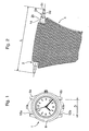
- FIG. 1 and 2 there is a watch case 1 and a conventional bracelet fastening bar 2, the bar 2 being shown mounted on the extreme link of a strand of bracelet 4.
- the box 1 includes so classic a middle 6 provided with two pairs of horns 8a, 8b for fixing the 4. These two pairs of horns 8a, 8b are arranged conventionally on opposite sides of the middle at 12 o'clock and 6 o'clock respectively.
- horns it will be understood in the context of the invention any element of various forms, defining between them a space intended to receive the end of a strand of bracelet provided with a bar of fixation. These horns can fit the shape but not necessarily. Note that the fasteners are attaching little or no to the case, or reported on the box, are also included in this general definition of horns.
- a blind hole 10a, 10b is formed in each facing face 12a, 12b horns 8a, 8b.
- these holes 10a, 10b can be provided through if you wish.
- the bars 2 comprise at each of their ends a pivot 2a movable to inside a central tube 2b.
- each pivot 2a is subject the action of a spring (not shown) housed inside the tube 2b, which pushes them towards the outside of the tube.
- the length L of the bar 2 taken from one end of a pivot 2a to the other is substantially greater than the distance D between the mutually opposite surfaces 12a, 12b of a pair of horns 8a, 8b.
- the pivots 2a must therefore be retracted at least partially to inside the tube 2b so that the bar can, at first, be inserted between the horns and in a second step that the pivots can be brought into the holes 10a, 10b in which they are lodged, it being understood that the tube 2b has a length less than the distance D.
- the pivots 2a have an end portion 2c of smaller diameter which defines a shoulder 2d. The latter thus offers a support surface for a tool with a view to disassembly of the bracelet.
- the bar 2 is disposed in a housing or eyelet 14 provided at one end of the bracelet 4.
- the term bracelet in the context of the invention includes any type of bracelet that can be attached to a box of shows using a bar to hold a watch on the wrist of a user, and includes not only soft bracelets, for example leather or plastic, but also metal link bracelets or not.
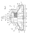
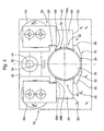
- FIGS. 3 to 5 there is shown a device 16 for the semi-automatic assembly of two bracelet strands 4 between the surfaces 12a, 12b, horns 8a, 8b or, in other words, for the automatic introduction of the pivots 2a of the bar 2 in the holes 10a, 10b horns 8a, 8b respectively.
- the assembly is said to be semi-automatic insofar as the operator must first insert the bar 2 into the housing or eyelet 14 and position the strands of bracelet in the mounting device 16.
- the device 16 is planned to simultaneously mount two strands of bracelet 4 on a box of shows 1, but it is understood that in a simplified version of the device 16 on could provide for a semi-automatic assembly of a bracelet strand after the other.
- the device 16 comprises two support assemblies 18, respectively 20, for the watch case 1 and for the bracelet strands 4, mobile relative to each other.
- the box support assembly 18 comprises a support block 22 of shape general prismatic having an upper portion 24 whose shape is substantially complementary to the shape of the lower face 26 of the box of shows 1 that it is intended to receive. More precisely, the upper part 24 comprises a central recess 28 surrounded by a peripheral support rim 30 on which box 1 can rest.
- the rim 30 comprises positioning means 32 of the box 1, made in this example in the form of a rib extending the along the rim of the side of the central recess 28. The rib 32 thus makes it possible to center box 1 on block 22.
- FIG. 4 also shows that the block 22 is associated with means keyed pins 34 for angularly orienting the box 1 relative to the block 22 or, in other words, to set up the watch case in the position desired on the block 22.
- These polarizing means 33 comprise in this case a notch for receiving the crown (not shown) of the box 1.
- the central recess 28, the flange 30 and the rib 32 present a circular shape to receive and position the watch box 1 of form general circular and whose lower face is also circular.
- the shape of the obviously 28, positioning means 32 and of the peripheral rim 30 can vary and is determined essentially by the shape the underside of the box 1 on which the bracelet is to be mounted.
- a layer of Teflon, trademark, is for example appropriate.
- the block 22 further comprises two lateral recesses 34 formed respectively in two of its diametrically opposite side faces 36.
- the lateral recesses 34 are in the form of a groove extending in one direction perpendicular to the plane of the upper part 24 or parallel to the direction of the relative motion of the sets 18 and 20.
- the lateral recesses or grooves 34 have side walls 38 disposed opposite one another and a bottom wall 40. Each wall 38 forms a cam surface ( Figure 5).
- the side walls 38 are intended to cooperate with the pins 2a of the bars 2 to retract them at least partially to inside the tube 2b as will be explained in more detail below.
- the cam surfaces 38 comprise two successive sections 38a, 38b, respectively a first section 38a in which the side walls diverge towards the lower part of block 22 to the base of the latter, and a second section 38b wherein the side walls are substantially parallel.
- section 38b the side walls 38 are separated from one another by distance substantially equal to the distance D separating the surfaces 12a, 12b mutually opposed horns 8a, 8b of the box 1.
- the walls lateral portions of section 38a form between them an apex angle of between 25 and 40 °.
- the block 22 is fixed to a slide 42 sliding along a guide column 44 which extends perpendicular to a base 46 in a which it is fixed.
- the assembly 18 forms a moving element with respect to 20.
- the base 46 extends in a plane substantially perpendicular to the longitudinal direction of the lateral recesses 34.
- the assembly 18 further comprises recall means 48 of the latter in a so-called loading position which will be described in more detail below.
- the return means 48 are formed of a helical spring which extends around the guide column 44 between the base 46 and the base of the slide 42, the spring 48 acting on the latter to push it in the direction of the arrow R ( Figure 3) to the loading position.
- the slide 42 comes in abutment on a stop element 50 integral with the guide column 44.
- This element stop 50 is for example constituted by a simple nut.
- the support assembly 20 of the bracelet strands comprises two consoles 52, one for each strand of the bracelet, respectively fixed on integral pillars 54 of the base 46 and arranged on either side of the guide column 44.
- These consoles 52 are for example made of nylon while the pillars 54 are made in steel.
- An end portion 56 of the brackets 52 extends up between the walls lateral portions 38 of the recesses 34.
- Each console 52 has a width adapted to the width of the bracelet strand that it supports, the portion 56 of the console 52 extending between the side walls 38 having a width Lc substantially less than the distance D separating the walls of section 38b.
- the end faces 58 of the parts extremes 56 respectively have a shape complementary to the wall of bottom 34 of the recesses 34.
- the end faces 58 thus slide along the walls 40 during the relative movement of block 22 and brackets 52.
- bottom walls 40 advantageously comprise sliding and guiding surfaces 40a projecting in these walls 40. These surfaces 40a thus facilitate the relative movements of the consoles 52 and the block 22 on each other.
- the upper surfaces 60 of the consoles 52 are inclined relative to the base 46, the inclination of these surfaces being adapted to the relative position of the watch case 1 and its bracelet 4 during assembly. This tilt therefore depends essentially on the geometry of the box demonstrates and the bracelet that must be assembled.
- the mounting device 16 further comprises actuating means 62 (FIG. 3) formed, in the illustrated example, of a pneumatic jack which acts by through a cleat 64 on the glass 68 of the watch case disposed on the block 22 to bring the latter into a low position called mounting.
- actuating means 62 FIG. 3
- FIG. 3 In drawing, for the actuating means 62, only the rod of the jack is shown.
- the block 22 is in the loading position, in other words, the slide 42 is in abutment against the stop nut 50 attached to the end of the column of 44.
- the block 22 is held in this position under the effect of the spring of recall 48.
- the operator sets up the watch case 1 on the block 22 so that it rests on the block 22 by its lower face 26.
- the polarizing means 33 facilitate the setting up of the box 1.
- the operator then introduces the fixing bars 2 into the housing or eyelet 14 provided at the ends of the bracelet strands 4.
- the bracelet strands 4 provided with their strips 2 are then placed on the consoles 52 so that they rest by their lower faces on the upper surfaces 60 thereof and that their ends equipped with the bars are kept at a distance from each other which corresponds to the distance in their final position once mounted on the watch box.
- the bracelet 4 is an articulated link bracelet whose two strands are connected together by a clasp 66. Part of these strands rests in this case on the base 46 in a region below the brackets 52 and the block 22.
- the cleat 64 moves in the direction of arrow M until it comes into contact with the top of the watch glass 68.
- the actuating means 62 move then the block 22 along the guide column 44 in the direction M.
- the cam surfaces of section 38a are getting closer, because of their inclination, pivots 2c until coming into contact with these cam surfaces 38a.
- the surfaces 38a then gradually penetrate the pivots 2a inside. tubes 2b to retract at least partially in the latter.
- the displacement in the direction M continues so that the pivots 2a come then in contact with the section 38b of the cam surfaces 38.
- the pivots 2a are thus kept retracted until block 22 is moved sufficiently for that the pivots are opposite the holes 10a, 10b formed in the horns 8a, 8b. AT this moment, the pivots 2a pushed outwards by the spring housed in the tube 2b enter the holes 10a, 10b.
- the bracelet 4 is then mounted on the box 1. The operator then triggers the actuating means 62 which releases the box 1 and allows the block 22 to return to its loading position.
- the device 16 and its operation that have just been described are particularly suitable for mounting link bracelets in which the end face 70 of the extreme links is configured to fit the shape of the space between the horns of the box 1.
- the bottom 40 of the groove 34, and more particularly the sliding and guiding surfaces 38a form an abutment against which the end face 70 of the extreme link is based when the bracelet strand is placed on the upper surface of the console, which defines a specific position of the bracelet strand for mounting.
- an embodiment variant is also provided. particularly suitable for mounting link bracelets in which the face frontal 70 of the extreme link is not configured to fit the shape of space located between the horns of the box. This is the case for a significant part of leather bracelets in particular.
- FIG 6 there is illustrated in perspective a portion of the block 22 and a box of shows 1 resting on the bearing flange 30 according to this variant.
- a guide groove 72 for the pivots 2a is arranged in the sections 38a and 38b of each of the cam surfaces 38.
- the groove 72 presents generally the shape of an "L", the portion 74 forming the horizontal leg of the L being open towards the outside and towards the base, and the part 76 forming the branch vertical line of the L extending parallel to the direction of movement of the block 22 and opening onto the support flange 30.
- part 76 is flared in its lower region and that it is narrows in its upper region until reaching the diameter of the pivots 2a.
- This configuration of the groove 72 facilitates the correct positioning of the pivots 2a of the bar 2 when placing the bracelet strands 4 on the brackets 52 and allows progressive guidance of the pivots 2a during the assembly movement of the block 22.
- lateral surfaces 12a, 12b of the horns 8a, 8b in which holes are provided 10a, 10b for receiving the ends of the bar 2, comprise each a groove 78 which extends substantially in a perpendicular direction to the plane of the box 1.
- These grooves 78 extend from the base 80 (FIG. horns 8a, 8b into the holes 10a, 10b.
- the grooves 78 have a depth less than the depth of said fixing holes 10a, 10b.
- each block 22 and in particular the positioning means 32 must be adapted to the shape of a particular box so that once positioned on the block 22, the grooves 72 and 78 are in correspondence.
- the skilled person can easily provide for removable fastening means suitable for securing the block 22 on the slider 42.
- FIG. 8 another variant of the mounting device according to FIG. the invention.
- This variant embodiment is adapted more particularly to bracelet fixation systems whose nature of the barrettes do not allow the simultaneous introduction of the pivots 2a of the bar in the holes of horns, by example when one of the pivots is not retractable or when the length of the bar in its compressed state is greater than the distance separating the surfaces mutually opposite horns.
- each console 52 of the mounting device 16 is associated intermediate support means 82 for each bracelet strand.
- These means support 82 make it possible to present the bracelet strands in an inclined manner by relative to the upper surface 60 of the consoles 52.
- These support means 82 comprise a base plate 84 on which is hinged a support plate 86 for receiving a bracelet strand 4.
- Elastic return means 88 formed by a spring in the illustrated example, are arranged between the base plate 84 and the support plate 86. These return means 88 tend to separate the two plates from each other.
- the axis of articulation 90 of the plates 84 and 86 on top of each other is substantially parallel to the longitudinal direction of the bracelet strands.
- the plaque 84 is fixed on the upper face of the console for example by screws 92 whose axis features have simply been represented.
- the strands of the bracelet 4 are positioned longitudinally on the support plate 86, for example using a stop (not shown), so that during the movement, the pivots 2a are introduced and slide in the grooves 72.
- the support plate 86 being inclined, one of the two pivots 2a comes in a first phase to lodge and therefore block in a hole 10a of horn.
- the relative movement of block 22 and consoles 52 continues and the hinged support plate 86 compresses the spring 88 until the second pivot 2a is housed in the hole 10a horn which is associated with him.
- the bracelet is then mounted.
- the spring 88 is compressed and the support plate 86 is parallel to the base plate 84 as illustrated in FIG. dotted in FIG. 9.
- the actuating means 62 are then triggered, the block 22 returns to its loading position, the watch with its bracelet is then withdrawn.
- the device 16 is then again ready for a new operation of mounting.
Landscapes
- Physics & Mathematics (AREA)
- General Physics & Mathematics (AREA)
- Buckles (AREA)
- Telephone Set Structure (AREA)
- Electric Clocks (AREA)
- Casings For Electric Apparatus (AREA)
Description
- la figure 1 est une vue en élévation d'une boíte de montre typique de l'art antérieur;
- la figure 2 est une vue partielle en perspective d'un brin de bracelet muni d'une barrette de fixation de l'art antérieur ;
- la figure 3 est une vue de face partiellement coupée d'un dispositif de montage d'un brin de bracelet sur une boíte de montre selon l'invention, la boíte de montre et le bracelet étant représentés sur le dispositif avant le montage;
- la figure 4 est une vue de dessus d'un dispositif de montage d'un brin de bracelet sur une boíte de montre selon l'invention, la boíte de montre et les brins de bracelet ayant été omis;
- la figure 5 est une vue selon la flèche F de la figure 3 d'un dispositif de montage d'un brin de bracelet sur une boíte de montre selon l'invention ;
- la figure 6 montre un détail d'une première variante de réalisation du dispositif de montage selon l'invention;
- la figure 7 est une vue partielle en perspective d'une boíte de montre selon l'invention particulièrement adaptée à une utilisation avec le dispositif selon l'invention illustré à la figure 6, et
- la figure 8 est vue selon la flèche F de la figure 3 illustrant une variante de réalisation du dispositif de montage selon l'invention.
Claims (19)
- Dispositif pour le montage semi automatique d'un brin souple (4) notamment d'un bracelet ou d'une ceinture entre les surfaces mutuellement opposées (12a, 12b) d'un évidement d'un objet notamment d'une boíte de montre (1) ou d'une boucle à raccorder au brin souple, ledit brin souple (4) comportant à une de ses extrémités une barrette de fixation (2) munie de deux pivots (2a) dont au moins un est escamotable et destinés à être engagés dans des trous (10a, 10b) prévus dans lesdites surfaces (12a, 12b) de l'évidement ledit dispositif (16) étant caractérisé en ce qu'il comprend deux ensembles de support (18, 20), respectivement pour l'objet (1) et pour ledit brin souple (4), mobiles l'un par rapport à l'autre, ledit ensemble support (18) de l'objet (1) comprenant deux surfaces de cames (38) mutuellement opposées et s'étendant sensiblement perpendiculairement à ladite barrette (2), lesdites surfaces de cames (38) agissant sur les pivots (2a) de la barrette (2) pour les escamoter au moins partiellement lors du mouvement relatif de l'ensemble support (20) du brin souple (4) et de l'ensemble support (18) de l'objet (1), ledit mouvement amenant lesdits pivots en regard desdits trous (10a, 10b) pour assurer le montage dudit brin (4).
- Dispositif de montage selon la revendication 1, caractérisé en ce que l'ensemble de support (18) de l'objet (1) comporte un bloc de support (22) présentant une partie supérieure (24) comprenant des moyens de positionnement (32) de l'objet (1), et au moins un évidement (34) disposé en regard de l'évidemment de l'objet (1), lesdites surfaces de cames (38) étant disposées le long des parois latérales (36) en regard dudit évidement (34) du bloc de support et sensiblement parallèlement à la direction dudit mouvement.
- Dispositif de montage selon la revendication 1 ou 2, caractérisé en ce que lesdites surfaces de cames (38) comprennent deux sections (38a, 38b) successives respectivement une première section (38a) dans laquelle les parois latérales (36) de l'évidement (34) du bloc divergent en direction dudit ensemble de support (20) du brin souple (4) et une deuxième section (38b) dans laquelle les parois latérales (36) sont sensiblement parallèles.
- Dispositif de montage selon la revendication 3, caractérisé en ce que lesdites parois latérales de la première section (38a) forment entre elles un angle au sommet compris entre 25 ° et 40°.
- Dispositif de montage selon l'une des revendications précédentes, caractérisé en ce que ledit ensemble de support (20) du brin souple (4) comporte une console de support (52) destinée à recevoir au moins une extrémité du brin souple (4) équipé de sa barrette de fixation (2), ladite console de support (52) s'étendant jusqu'entre lesdites parois latérales (36) dudit évidement (34 du bloc.
- Dispositif de montage selon la revendication 5, caractérisé en ce que la face d'extrémité (58) de la console de support (52) présente une forme complémentaire de la paroi de fond (40) dudit évidement (34) du bloc et en ce que ladite face d'extrémité (58) coulisse le long de ladite paroi de fond (40) lors du mouvement relatif desdits deux ensembles de support (18, 20).
- Dispositif de montage selon l'une des revendications 5 ou 6, caractérisé en ce ladite console de support (52) comprend une surface supérieure (60) recevant le brin souple (4) et en ce que ladite surface supérieure (60) est inclinée par rapport à la partie supérieure (24) du bloc de support de l'objet (18).
- Dispositif de montage selon l'une des revendications 2 à 7, caractérisé en ce que le fond (40) de l'évidemment (34) du bloc présente une forme sensiblement identique à celui de l'objet (1).
- Dispositif de montage selon l'une quelconque des revendications précédentes, caractérisé en ce que l'ensemble support (18) de l'objet (1) est mobile par rapport à l'ensemble support (20) du brin souple (4) entre une première position dite de chargement dans laquelle l'objet (1) et le brin souple (4) sont mis en place sur le dispositif (16) et une deuxième position dite de montage dans laquelle le montage du brin souple (4) sur l'objet (1) s'effectue.
- Dispositif de montage selon la revendication 9, caractérisé en ce que le bloc de support (22) est relié à un coulisseau (42) se déplaçant à coulissement le long d'une colonne de guidage (44) qui s'étend perpendiculairement par rapport à une embase (46) dans laquelle elle est fixée.
- Dispositif de montage selon la revendication 9 ou 10, caractérisé en ce que l'ensemble de support (18) de l'objet (1) est mis en mouvement par un actionneur (62) qui agit directement sur l'objet (1).
- Dispositif de montage selon la revendication 11, caractérisé en ce que l'ensemble de support (18) de l'objet (1) est muni de moyens de rappel (48) dudit ensemble vers la position de chargement.
- Dispositif de montage selon l'une quelconque des revendications 2 à 12. caractérisé en ce que la paroi de fond (40) dudit évidement (34) du bloc forme une surface de butée pour l'extrémité du brin souple (4).
- Dispositif de montage selon l'une des revendications précédentes pour le montage de deux brins de bracelet entre les surfaces mutuellement opposées (12a, 12b) des cornes (8a, 8b) d'une boíte de montre (1), caractérisé en ce que le bloc de support (22) présente deux évidements (34) disposés respectivement en regard des espaces situés entre les deux paires de cornes (8a, 8b), lesdites surfaces de cames (38) s'étendant sur les parois latérales (36) en regard desdits évidemment (34) du bloc et sensiblement parallèlement à la direction dudit mouvement.
- Dispositif de montage selon l'une quelconque des revendications précédentes, caractérisé en ce qu'une rainure de guidage (72) pour les pivots (2a) est arrangée dans les sections (38a, 38b) de chacune des surfaces de cames (38).
- Dispositif de montage selon la revendication 15, caractérisé en ce ladite rainure (72) présente la forme d'un « L », la partie (74) formant la branche horizontale du L étant ouverte vers l'extérieur et vers l'embase (46) et la partie (76) formant la branche verticale du L s'étendant parallèlement à la direction du mouvement du bloc (18) et débouchant dans la partie supérieure du bloc (18).
- Dispositif de montage selon l'une quelconque des revendications 5 à 15, caractérisé en ce que les consoles de support (52) sont associées à des moyens de support intermédiaire (82) pour chaque brin souple (4), ces moyens de support (82) permettant de présenter les brins de bracelet (4) de manière inclinée par rapport à la surface supérieure (60) des console (52).
- Dispositif de montage selon la revendication 17, caractérisé en ce que les moyens de support intermédiaire (84) comprennent une plaque de base (84) sur laquelle est articulée une plaque de support (86) destinée à recevoir un brin souple(4).
- Dispositif de montage selon la revendication 18, caractérisé en ce que des moyens de rappel élastiques (88) sont disposés entre la plaque de base (84) et la plaque de support (86), ces moyens de rappel (88) tendant à écarter lesdites deux plaques (84, 86) l'une de l'autre, l'axe d'articulation des plaques (84, 86) l'une sur l'autre étant sensiblement parallèle à la direction longitudinale du brin souple (4).
Priority Applications (1)
| Application Number | Priority Date | Filing Date | Title |
|---|---|---|---|
| EP01271981A EP1346263B1 (fr) | 2000-12-22 | 2001-11-09 | Dispositif pour le montage d'un brin souple notamment sur une boite de montre et procede de montage d'un tel brin souple |
Applications Claiming Priority (4)
| Application Number | Priority Date | Filing Date | Title |
|---|---|---|---|
| EP00204731 | 2000-12-22 | ||
| EP00204731A EP1220060A1 (fr) | 2000-12-22 | 2000-12-22 | Dispositif pour le montage d'un brin souple notamment sur une boíte de montre et boíte de montre et procédé de montage d'un tel brin souple |
| PCT/EP2001/013111 WO2002052359A1 (fr) | 2000-12-22 | 2001-11-09 | Dispositif pour le montage d'un brin souple notamment sur une boîte de montre et procede de montage d'un tel brin souple |
| EP01271981A EP1346263B1 (fr) | 2000-12-22 | 2001-11-09 | Dispositif pour le montage d'un brin souple notamment sur une boite de montre et procede de montage d'un tel brin souple |
Publications (2)
| Publication Number | Publication Date |
|---|---|
| EP1346263A1 EP1346263A1 (fr) | 2003-09-24 |
| EP1346263B1 true EP1346263B1 (fr) | 2005-11-23 |
Family
ID=8172512
Family Applications (2)
| Application Number | Title | Priority Date | Filing Date |
|---|---|---|---|
| EP00204731A Withdrawn EP1220060A1 (fr) | 2000-12-22 | 2000-12-22 | Dispositif pour le montage d'un brin souple notamment sur une boíte de montre et boíte de montre et procédé de montage d'un tel brin souple |
| EP01271981A Expired - Lifetime EP1346263B1 (fr) | 2000-12-22 | 2001-11-09 | Dispositif pour le montage d'un brin souple notamment sur une boite de montre et procede de montage d'un tel brin souple |
Family Applications Before (1)
| Application Number | Title | Priority Date | Filing Date |
|---|---|---|---|
| EP00204731A Withdrawn EP1220060A1 (fr) | 2000-12-22 | 2000-12-22 | Dispositif pour le montage d'un brin souple notamment sur une boíte de montre et boíte de montre et procédé de montage d'un tel brin souple |
Country Status (4)
| Country | Link |
|---|---|
| EP (2) | EP1220060A1 (fr) |
| AT (1) | ATE310977T1 (fr) |
| DE (1) | DE60115287D1 (fr) |
| WO (1) | WO2002052359A1 (fr) |
Cited By (1)
| Publication number | Priority date | Publication date | Assignee | Title |
|---|---|---|---|---|
| WO2022124602A1 (fr) * | 2020-12-07 | 2022-06-16 | 삼성전자 주식회사 | Dispositif électronique vestimentaire comprenant une structure d'attache |
Families Citing this family (3)
| Publication number | Priority date | Publication date | Assignee | Title |
|---|---|---|---|---|
| US9423771B2 (en) * | 2011-12-09 | 2016-08-23 | Cartier International Ag | Method for placing a watch case under a protective atmosphere |
| WO2017012948A1 (fr) * | 2015-07-17 | 2017-01-26 | Sevenfriday AG | Procédé et dispositif de fixation de bracelet à une montre-bracelet |
| CH718103A1 (fr) * | 2020-11-30 | 2022-05-31 | Richemont Int Sa | Boucle démontable sans outils. |
Family Cites Families (3)
| Publication number | Priority date | Publication date | Assignee | Title |
|---|---|---|---|---|
| CH911167A4 (de) * | 1967-06-27 | 1969-04-30 | Gerber & Cotting | Vorrichtung zum automatischen Einsetzen von Federstegen und Verfahren zum Betrieb dieser Vorrichtung |
| US4285450A (en) * | 1980-02-25 | 1981-08-25 | Barnes Mary K | Watch band pin connector assembly |
| JPH07231802A (ja) * | 1993-12-27 | 1995-09-05 | Citizen Watch Co Ltd | 腕時計における連結構造 |
-
2000
- 2000-12-22 EP EP00204731A patent/EP1220060A1/fr not_active Withdrawn
-
2001
- 2001-11-09 WO PCT/EP2001/013111 patent/WO2002052359A1/fr not_active Application Discontinuation
- 2001-11-09 DE DE60115287T patent/DE60115287D1/de not_active Expired - Lifetime
- 2001-11-09 AT AT01271981T patent/ATE310977T1/de not_active IP Right Cessation
- 2001-11-09 EP EP01271981A patent/EP1346263B1/fr not_active Expired - Lifetime
Cited By (1)
| Publication number | Priority date | Publication date | Assignee | Title |
|---|---|---|---|---|
| WO2022124602A1 (fr) * | 2020-12-07 | 2022-06-16 | 삼성전자 주식회사 | Dispositif électronique vestimentaire comprenant une structure d'attache |
Also Published As
| Publication number | Publication date |
|---|---|
| DE60115287D1 (de) | 2005-12-29 |
| EP1220060A1 (fr) | 2002-07-03 |
| WO2002052359A1 (fr) | 2002-07-04 |
| EP1346263A1 (fr) | 2003-09-24 |
| ATE310977T1 (de) | 2005-12-15 |
Similar Documents
| Publication | Publication Date | Title |
|---|---|---|
| CA1140178A (fr) | Dispositif de liaison d'une chaussure avec un ski, notamment pour la pratique du ski de fond | |
| EP3473127B1 (fr) | Dispositif de fixation d'un bracelet | |
| FR2859510A1 (fr) | Structure d'assemblage | |
| EP0904572A1 (fr) | Dispositif pour la fixation d'un bracelet a une boite de montre | |
| FR3049247A1 (fr) | Adaptateur de raccordement de l'extremite libre d'un bras d'essuie-glace, et ensemble comportant un adaptateur et un bras d'essuie-glace | |
| EP1654950A1 (fr) | Fermoir de bracelet | |
| EP1346263B1 (fr) | Dispositif pour le montage d'un brin souple notamment sur une boite de montre et procede de montage d'un tel brin souple | |
| WO1994028754A1 (fr) | Fermoir du type a boucle deployante pour bracelet | |
| EP1103201B1 (fr) | Articulation à ressort caché pour article de chevelure | |
| FR2497674A2 (fr) | Dispositif de fixation d'une chaussure a un ski | |
| FR2609507A1 (fr) | Dispositif de maintien de produits en forme de tiges | |
| EP3941300B1 (fr) | Fermoir pour bracelet | |
| WO2003005854A1 (fr) | Dispositif pour maintenir sur un vetement porté ou toute autre sorte de support une paire de lunettes pour permettre de ne pas la perdre dans des conditions extremes | |
| FR2854147A1 (fr) | Machine a convoyeur pour la fabrication de brochettes | |
| EP3587224B1 (fr) | Dispositif de fixation d'une roue de secours d'un véhicule automobile | |
| EP3432087A1 (fr) | Dispositif de fixation | |
| FR3133300A1 (fr) | Fermoir a boucle deployante | |
| CH719481A2 (fr) | Fermoir a boucle deployante. | |
| EP3379344B1 (fr) | Bracelet souple a largeur adaptable | |
| EP0528700A1 (fr) | Pince porte-briquet ajustable | |
| EP0784251A1 (fr) | Agencement de fixation d'un bracelet sur une montre | |
| FR2631842A1 (fr) | Dispositif d'appui de la partie anterieure de la semelle d'une chaussure sur un ski | |
| FR3041441A1 (fr) | Dispositif permettant la liaison et la separation d’un boitier de montre avec un bracelet de montre | |
| CH713613A2 (fr) | Fermoir à boucle déployante. | |
| CH714009A2 (fr) | Dispositif électronique portable comportant un boîtier, au moins un brin de bracelet et un connecteur électrique. |
Legal Events
| Date | Code | Title | Description |
|---|---|---|---|
| PUAI | Public reference made under article 153(3) epc to a published international application that has entered the european phase |
Free format text: ORIGINAL CODE: 0009012 |
|
| 17P | Request for examination filed |
Effective date: 20030722 |
|
| AK | Designated contracting states |
Kind code of ref document: A1 Designated state(s): AT BE CH CY DE DK ES FI FR GB GR IE IT LI LU MC NL PT SE TR |
|
| AX | Request for extension of the european patent |
Extension state: AL LT LV MK RO SI |
|
| GRAP | Despatch of communication of intention to grant a patent |
Free format text: ORIGINAL CODE: EPIDOSNIGR1 |
|
| GRAS | Grant fee paid |
Free format text: ORIGINAL CODE: EPIDOSNIGR3 |
|
| GRAA | (expected) grant |
Free format text: ORIGINAL CODE: 0009210 |
|
| AK | Designated contracting states |
Kind code of ref document: B1 Designated state(s): AT BE CH CY DE DK ES FI FR GB GR IE IT LI LU MC NL PT SE TR |
|
| PG25 | Lapsed in a contracting state [announced via postgrant information from national office to epo] |
Ref country code: IT Free format text: LAPSE BECAUSE OF FAILURE TO SUBMIT A TRANSLATION OF THE DESCRIPTION OR TO PAY THE FEE WITHIN THE PRESCRIBED TIME-LIMIT;WARNING: LAPSES OF ITALIAN PATENTS WITH EFFECTIVE DATE BEFORE 2007 MAY HAVE OCCURRED AT ANY TIME BEFORE 2007. THE CORRECT EFFECTIVE DATE MAY BE DIFFERENT FROM THE ONE RECORDED. Effective date: 20051123 Ref country code: NL Free format text: LAPSE BECAUSE OF FAILURE TO SUBMIT A TRANSLATION OF THE DESCRIPTION OR TO PAY THE FEE WITHIN THE PRESCRIBED TIME-LIMIT Effective date: 20051123 Ref country code: IE Free format text: LAPSE BECAUSE OF FAILURE TO SUBMIT A TRANSLATION OF THE DESCRIPTION OR TO PAY THE FEE WITHIN THE PRESCRIBED TIME-LIMIT Effective date: 20051123 Ref country code: AT Free format text: LAPSE BECAUSE OF FAILURE TO SUBMIT A TRANSLATION OF THE DESCRIPTION OR TO PAY THE FEE WITHIN THE PRESCRIBED TIME-LIMIT Effective date: 20051123 Ref country code: FI Free format text: LAPSE BECAUSE OF FAILURE TO SUBMIT A TRANSLATION OF THE DESCRIPTION OR TO PAY THE FEE WITHIN THE PRESCRIBED TIME-LIMIT Effective date: 20051123 Ref country code: GB Free format text: LAPSE BECAUSE OF FAILURE TO SUBMIT A TRANSLATION OF THE DESCRIPTION OR TO PAY THE FEE WITHIN THE PRESCRIBED TIME-LIMIT Effective date: 20051123 |
|
| REG | Reference to a national code |
Ref country code: GB Ref legal event code: FG4D Free format text: NOT ENGLISH |
|
| REG | Reference to a national code |
Ref country code: CH Ref legal event code: EP |
|
| REF | Corresponds to: |
Ref document number: 60115287 Country of ref document: DE Date of ref document: 20051229 Kind code of ref document: P |
|
| REG | Reference to a national code |
Ref country code: IE Ref legal event code: FG4D Free format text: LANGUAGE OF EP DOCUMENT: FRENCH |
|
| PG25 | Lapsed in a contracting state [announced via postgrant information from national office to epo] |
Ref country code: SE Free format text: LAPSE BECAUSE OF FAILURE TO SUBMIT A TRANSLATION OF THE DESCRIPTION OR TO PAY THE FEE WITHIN THE PRESCRIBED TIME-LIMIT Effective date: 20060223 Ref country code: DK Free format text: LAPSE BECAUSE OF FAILURE TO SUBMIT A TRANSLATION OF THE DESCRIPTION OR TO PAY THE FEE WITHIN THE PRESCRIBED TIME-LIMIT Effective date: 20060223 Ref country code: GR Free format text: LAPSE BECAUSE OF FAILURE TO SUBMIT A TRANSLATION OF THE DESCRIPTION OR TO PAY THE FEE WITHIN THE PRESCRIBED TIME-LIMIT Effective date: 20060223 |
|
| PG25 | Lapsed in a contracting state [announced via postgrant information from national office to epo] |
Ref country code: DE Free format text: LAPSE BECAUSE OF FAILURE TO SUBMIT A TRANSLATION OF THE DESCRIPTION OR TO PAY THE FEE WITHIN THE PRESCRIBED TIME-LIMIT Effective date: 20060224 |
|
| PG25 | Lapsed in a contracting state [announced via postgrant information from national office to epo] |
Ref country code: ES Free format text: LAPSE BECAUSE OF FAILURE TO SUBMIT A TRANSLATION OF THE DESCRIPTION OR TO PAY THE FEE WITHIN THE PRESCRIBED TIME-LIMIT Effective date: 20060306 |
|
| REG | Reference to a national code |
Ref country code: CH Ref legal event code: NV Representative=s name: ICB INGENIEURS CONSEILS EN BREVETS SA |
|
| PG25 | Lapsed in a contracting state [announced via postgrant information from national office to epo] |
Ref country code: PT Free format text: LAPSE BECAUSE OF FAILURE TO SUBMIT A TRANSLATION OF THE DESCRIPTION OR TO PAY THE FEE WITHIN THE PRESCRIBED TIME-LIMIT Effective date: 20060424 |
|
| NLV1 | Nl: lapsed or annulled due to failure to fulfill the requirements of art. 29p and 29m of the patents act | ||
| GBV | Gb: ep patent (uk) treated as always having been void in accordance with gb section 77(7)/1977 [no translation filed] |
Effective date: 20051123 |
|
| REG | Reference to a national code |
Ref country code: IE Ref legal event code: FD4D |
|
| PLBE | No opposition filed within time limit |
Free format text: ORIGINAL CODE: 0009261 |
|
| STAA | Information on the status of an ep patent application or granted ep patent |
Free format text: STATUS: NO OPPOSITION FILED WITHIN TIME LIMIT |
|
| 26N | No opposition filed |
Effective date: 20060824 |
|
| PG25 | Lapsed in a contracting state [announced via postgrant information from national office to epo] |
Ref country code: BE Free format text: LAPSE BECAUSE OF NON-PAYMENT OF DUE FEES Effective date: 20061130 Ref country code: MC Free format text: LAPSE BECAUSE OF NON-PAYMENT OF DUE FEES Effective date: 20061130 |
|
| REG | Reference to a national code |
Ref country code: FR Ref legal event code: ST Effective date: 20070731 |
|
| BERE | Be: lapsed |
Owner name: VAUCHER OUTILLAGE HORLOGER Effective date: 20061130 |
|
| PG25 | Lapsed in a contracting state [announced via postgrant information from national office to epo] |
Ref country code: FR Free format text: LAPSE BECAUSE OF NON-PAYMENT OF DUE FEES Effective date: 20061130 |
|
| PG25 | Lapsed in a contracting state [announced via postgrant information from national office to epo] |
Ref country code: LU Free format text: LAPSE BECAUSE OF NON-PAYMENT OF DUE FEES Effective date: 20061109 Ref country code: TR Free format text: LAPSE BECAUSE OF FAILURE TO SUBMIT A TRANSLATION OF THE DESCRIPTION OR TO PAY THE FEE WITHIN THE PRESCRIBED TIME-LIMIT Effective date: 20051123 |
|
| PG25 | Lapsed in a contracting state [announced via postgrant information from national office to epo] |
Ref country code: CY Free format text: LAPSE BECAUSE OF FAILURE TO SUBMIT A TRANSLATION OF THE DESCRIPTION OR TO PAY THE FEE WITHIN THE PRESCRIBED TIME-LIMIT Effective date: 20051123 |
|
| REG | Reference to a national code |
Ref country code: CH Ref legal event code: NV Representative=s name: BOVARD AG, CH Ref country code: CH Ref legal event code: PFA Owner name: VOH SA, CH Free format text: FORMER OWNER: VAUCHER OUTILLAGE HORLOGER, CH |
|
| PGFP | Annual fee paid to national office [announced via postgrant information from national office to epo] |
Ref country code: CH Payment date: 20161114 Year of fee payment: 16 |
|
| PG25 | Lapsed in a contracting state [announced via postgrant information from national office to epo] |
Ref country code: LI Free format text: LAPSE BECAUSE OF NON-PAYMENT OF DUE FEES Effective date: 20171130 Ref country code: CH Free format text: LAPSE BECAUSE OF NON-PAYMENT OF DUE FEES Effective date: 20171130 |