EP1345345B1 - Wide band raman amplifiers - Google Patents
Wide band raman amplifiers Download PDFInfo
- Publication number
- EP1345345B1 EP1345345B1 EP03005729A EP03005729A EP1345345B1 EP 1345345 B1 EP1345345 B1 EP 1345345B1 EP 03005729 A EP03005729 A EP 03005729A EP 03005729 A EP03005729 A EP 03005729A EP 1345345 B1 EP1345345 B1 EP 1345345B1
- Authority
- EP
- European Patent Office
- Prior art keywords
- pump
- wavelengths
- pump sources
- wavelength
- fiber
- Prior art date
- Legal status (The legal status is an assumption and is not a legal conclusion. Google has not performed a legal analysis and makes no representation as to the accuracy of the status listed.)
- Expired - Lifetime
Links
Images


Classifications
-
- H—ELECTRICITY
- H04—ELECTRIC COMMUNICATION TECHNIQUE
- H04B—TRANSMISSION
- H04B10/00—Transmission systems employing electromagnetic waves other than radio-waves, e.g. infrared, visible or ultraviolet light, or employing corpuscular radiation, e.g. quantum communication
- H04B10/29—Repeaters
- H04B10/291—Repeaters in which processing or amplification is carried out without conversion of the main signal from optical form
- H04B10/2912—Repeaters in which processing or amplification is carried out without conversion of the main signal from optical form characterised by the medium used for amplification or processing
- H04B10/2916—Repeaters in which processing or amplification is carried out without conversion of the main signal from optical form characterised by the medium used for amplification or processing using Raman or Brillouin amplifiers
-
- H—ELECTRICITY
- H01—ELECTRIC ELEMENTS
- H01S—DEVICES USING THE PROCESS OF LIGHT AMPLIFICATION BY STIMULATED EMISSION OF RADIATION [LASER] TO AMPLIFY OR GENERATE LIGHT; DEVICES USING STIMULATED EMISSION OF ELECTROMAGNETIC RADIATION IN WAVE RANGES OTHER THAN OPTICAL
- H01S3/00—Lasers, i.e. devices using stimulated emission of electromagnetic radiation in the infrared, visible or ultraviolet wave range
- H01S3/30—Lasers, i.e. devices using stimulated emission of electromagnetic radiation in the infrared, visible or ultraviolet wave range using scattering effects, e.g. stimulated Brillouin or Raman effects
- H01S3/302—Lasers, i.e. devices using stimulated emission of electromagnetic radiation in the infrared, visible or ultraviolet wave range using scattering effects, e.g. stimulated Brillouin or Raman effects in an optical fibre
-
- H—ELECTRICITY
- H04—ELECTRIC COMMUNICATION TECHNIQUE
- H04B—TRANSMISSION
- H04B10/00—Transmission systems employing electromagnetic waves other than radio-waves, e.g. infrared, visible or ultraviolet light, or employing corpuscular radiation, e.g. quantum communication
- H04B10/25—Arrangements specific to fibre transmission
- H04B10/2507—Arrangements specific to fibre transmission for the reduction or elimination of distortion or dispersion
- H04B10/2543—Arrangements specific to fibre transmission for the reduction or elimination of distortion or dispersion due to fibre non-linearities, e.g. Kerr effect
- H04B10/2563—Four-wave mixing [FWM]
-
- H—ELECTRICITY
- H01—ELECTRIC ELEMENTS
- H01S—DEVICES USING THE PROCESS OF LIGHT AMPLIFICATION BY STIMULATED EMISSION OF RADIATION [LASER] TO AMPLIFY OR GENERATE LIGHT; DEVICES USING STIMULATED EMISSION OF ELECTROMAGNETIC RADIATION IN WAVE RANGES OTHER THAN OPTICAL
- H01S3/00—Lasers, i.e. devices using stimulated emission of electromagnetic radiation in the infrared, visible or ultraviolet wave range
- H01S3/05—Construction or shape of optical resonators; Accommodation of active medium therein; Shape of active medium
- H01S3/06—Construction or shape of active medium
- H01S3/063—Waveguide lasers, i.e. whereby the dimensions of the waveguide are of the order of the light wavelength
- H01S3/067—Fibre lasers
- H01S3/06754—Fibre amplifiers
-
- H—ELECTRICITY
- H01—ELECTRIC ELEMENTS
- H01S—DEVICES USING THE PROCESS OF LIGHT AMPLIFICATION BY STIMULATED EMISSION OF RADIATION [LASER] TO AMPLIFY OR GENERATE LIGHT; DEVICES USING STIMULATED EMISSION OF ELECTROMAGNETIC RADIATION IN WAVE RANGES OTHER THAN OPTICAL
- H01S3/00—Lasers, i.e. devices using stimulated emission of electromagnetic radiation in the infrared, visible or ultraviolet wave range
- H01S3/09—Processes or apparatus for excitation, e.g. pumping
- H01S3/091—Processes or apparatus for excitation, e.g. pumping using optical pumping
- H01S3/094—Processes or apparatus for excitation, e.g. pumping using optical pumping by coherent light
- H01S3/094096—Multi-wavelength pumping
Definitions
- This invention relates to Raman amplifiers, and more particularly to distributed Raman amplifiers with flat gain over a wide band of wavelengths.
- Optical transmission systems employ Wavelength Division Multiplexing (WDM) to increase information handling of an optical fiber transmission line, typically a long haul transmission line.
- WDM Wavelength Division Multiplexing
- Early WDM systems operated with a relatively narrow wavelength bandwidth, centered around 1550 nanometers, e.g. 1530-1565 nanometers, often referred to as the C-band. This is the wavelength region where standard silica based optical fibers have optimally low absorption.
- the new band referred to as the L-band
- the L-band is variously defined, but for the purpose of this description is 1570-1610 nanometers.
- Use of these added wavelengths substantially extends the capacity of WDM systems.
- Raman scattering is a process by which light incident on a medium is converted to light at a lower frequency than the incident light.
- the pump photons excite the molecule up to a virtual level (non-resonant state).
- the molecular state quickly decays to a lower energy level emitting a signal photon in the process. Because the pump photon is excited to a virtual level Raman gain can occur for a pump source at any wavelength.
- the difference in energy between the pump and signal photons is dissipated by the molecular vibrations of the host material. These vibrational levels determine the frequency shift and shape of the Raman gain curve.
- the frequency (or wavelength) difference between the pump and the signal photon is called the Stokes shift.
- the Stokes shift at which the maximum gain is obtained is ⁇ 13 THz. Due to the amorphous nature of silica the Raman gain curve is fairly broad in optical fibers.
- Raman scattering can occur at any wavelength, this can be exploited to advantage in a telecommunication system that contains multiple signal wavelengths by using Raman pumps at several different wavelengths to amplify the signals.
- the gain seen by a given wavelength is the superposition of the gain provided by all the pumps, taking into account the transfer of energy between the pumps due to Raman scattering.
- By properly weighting the power provided at each of the Raman pump wavelengths it is possible to obtain a signal gain versus wavelength profile in which there is a small difference between the gain seen by different signal wavelengths (this difference is called the gain ripple or gain flatness).
- FWM four-wave mixing
- the pump wavelengths are either time division multiplexed (TDM) together, or the frequency of the pump source is modulated (FM). Since the various pump wavelengths overlap for only a small distances along the fiber, FWM between the pump wavelengths should be eliminated or severely reduced
- the invention is based in part on an understanding that the FWM effect is not uniform for all pump wavelengths.
- the arrangement shown represents a distributed Raman optical fiber amplifier structure with transmission span 11, most typically an optical fiber.
- the transmission span 11 represents a fiber of substantial length, typically in excess of 1 km. It will be evident to those skilled that the figures in this description are not drawn to scale, and the elements are schematically shown. For purposes of illustrating the details of the description, the preferred embodiment of the invention, i.e. a distributed amplifier where the amplifier medium is the normal transmission span is shown. The principles of the invention also apply to discrete amplifiers, where the amplification medium is a dedicated length of optical fiber, or other suitable traveling wave medium.
- the length of fiber represented by 11 is preferably at least 500 m in length to allow for the optical interactions that produce signal amplification.
- the amplifier is typically end pumped, and counterpumped, as shown in the figure by pump source 13 coupled into the core of the fiber through coupler shown schematically at 12.
- Typical pump wavelengths are 14xx nanometers, but can also be at other wavelengths.
- the input signal is represented by 14, and the amplified signal output is shown at 16.
- the fiber comprises a core 21 and a cladding 22.
- the core of the fiber is typically Ge-doped silica. Alternatively, it may be doped with phosphorus, or other index modifying impurities, or combinations of these.
- the cladding layer is preferably a high silica material, i.e. at least 85% SiO 2 . In some preferred structures it may be pure silica, or fluorine-doped silica.
- the fiber also has a protective coating 23, typically a polymer coating.
- the dimensions of the structure shown in Fig. 2 may vary substantially.
- the cladding layer diameter is typically in the range 50-400 ⁇ m, and preferably 70-300 ⁇ m.
- the core diameter is typically 2 -12 ⁇ m.
- Optical fiber Raman amplifiers operate on the principle that light scattered in a silica based optical fiber has a wavelength lower than that of the incident light. This is illustrated schematically in Fig. 3, where a pump photon, ⁇ p , excites a molecule up to a virtual level (non-resonant state). The molecule quickly decays to a lower energy level emitting a signal photon, ⁇ s , in the process.
- An important point to note is that, because the pump photon is excited to a virtual level, Raman gain can occur for a pump source at any wavelength. The difference in energy between the pump and signal photons is dissipated by the molecular vibrations of the host material.
- the frequency (or wavelength) difference between the pump and the signal photon is called the Stokes shift.
- the Stokes shift at which maximum gain is obtained is ⁇ 13 THz. Due to the amorphous nature of silica the Raman gain curve is fairly broad in optical fibers.
- the normalized Raman gain spectrum for a Ge-doped optical fiber is shown in Fig. 4 as a function of frequency shift from the pump.
- Raman pumps at several different wavelengths may be used to amplify the signals, since Raman scattering can occur at any wavelength.
- the gain seen by a given wavelength is the superposition of the gain provided by all the pumps taking into account the transfer of energy between the pumps due to Raman scattering.
- By properly weighting the power provided at each of the Raman pump wavelengths it is possible to obtain a signal gain versus wavelength profile in which there is a small difference between the gain seen by different signal wavelengths. This difference is called the gain ripple or gain flatness, and may be expressed in dB as (Gmax-Gmin).
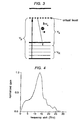
- FIG. 5 An example of a multiple pump system that is designed to produce a flat gain is shown in Fig. 5. Note that the power levels required at the longer wavelengths are significantly less than those at the shorter wavelengths.
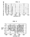
- Use of this multiple pump arrangement in a WDM Raman amplifier produces the output WDM signal shown in Fig. 6, where a relatively flat gain is obtained over the C-and L-bands.
- FWM four wave mixing
- vp1, vp2, and ⁇ p3 correspond to two or more individual pump wavelengths.
- FWM results from non-linear interaction between three wavelengths which, in the illustration given here, are three pump wavelengths. It is also possible for FWM to occur with only two pump wavelengths, and a third wavelength from another source that travels in the medium.
- spurious wavelength components resulting from FWM in the signal band may lead to transmission errors.
- the efficiency of FWM depends on a proper choice of frequencies and refractive indices. There are three contributions to the phase mismatch, material dispersion, waveguide dispersion and fiber nonlinearity.
- By manipulating the location of the zero dispersion wavelength (hence the waveguide dispersion) of the fiber very efficient FWM can occur. In practice this translates to either having a pump wavelength near the dispersion zero of the fiber, or two pumps with wavelengths on either side of the dispersion zero. It therefore becomes clear that as the number of pumps in a multi-pump wavelength Raman amplification scheme increases the likelihood of FWM increases.
- TDM time division multiplex
- Laser diode pump sources 71, 72, and 73 operating at 1480 nm, 1494 nm, and 1508 nm, respectively, are synchronized together and multiplexed into separate time slots represented by 74, 75 and 76.
- Pump sources 71 and 72 are combined in WDM combiner 81, and pump source 73 is added to 71 and 72 at WDM combiner 82. While the approach represented by Fig. 8 will aid in controlling FWM and other deleterious nonlinear effects, there are several problems with it.
- the backscatter peak at approximately 1527 nm is the result of FWM between the pump wavelengths 1508 nm, 1494 nm and 1480 nm. With reference to Fig. 7, these correspond to ⁇ p1, ⁇ p2, and ⁇ p3 respectively.
- the peak at 1527 corresponds to ⁇ FWM.
- the peak at approximately 1537 nm is the result of FWM where ⁇ p1 is 1494 nm, ⁇ p2 is 1480 nm, and ⁇ p3 is 1445 nm.
- the peak at approximately 1540 nm is the result of FWM where ⁇ p1 is 1508 nm, ⁇ p2 is 1494 nm, and ⁇ p3 is 1466 nm. From Fig. 7 it will be understood that all three pump wavelengths are necessary to produce the FWM peaks in Fig. 9. The recognition that the longer wavelengths are the main participants in the FWM for all three peaks, leads to one aspect of the invention. By multiplexing just the longer wavelengths, i.e. 1480 nm, 1494 nm, and 1508 nm, ensures that there is no time when all of the wavelengths necessary for FWM are present simultaneously. Therefore it is not necessary, in order to obtain the advantages of TDM multiple pump sources, to TDM ALL the multiple pump sources.
- Fig. 10 A system based on these principles is shown in Fig. 10. This results in a significant advance in terms of the factors enumerated above. Once it is recognized that fewer than all of the pump sources need to be multiplexed, the selection of those is straightforward. The measurements implicit in Fig. 9 follow well-known principles, and may be confirmed empirically.
- the swept diode of Fig. 10 (FM) and Fig. 11 may operate over the wavelength range 1480 nm - 1508 nm while the remaining pumps operating in the 1420 nm -1480 nm range are individual diodes operating CW.
- the multiple pump multiplexing technique is effective in a counter propagation configuration since the signal channels walk through the modulated pumps. If the pump powers are increased so as to compensate for the decreased interaction length, the path-averaged Raman gain is constant. The rate at which the TDM or FM source cycles through all the different pump wavelengths also has to be fast enough so that no gain dependent modulation of the signal power occurs. Past work on noise transfer from the pump to signal suggests that the overall repetition rate for all the pump wavelengths should be greater than 50 kHz. Each wavelength is then modulated approximately n times faster, where n is the number of wavelengths. Note that the modulation rate and required peak powers are linked. The higher the modulation rate the more peak power needed at a given wavelength.
- the length of the interaction be substantial, i.e. 1 km or more.
- This length may represent a transmission span operating in a distributed mode (typically longer than 1 km, i.e. 3-100 km) or may be an optical fiber used in a discrete amplifier device.
- the 2nd order pump It takes a finite length of fiber for the 2 nd order pump to be converted to the 1st order pump.
- the 1 st order pump then pumps the signal. This then allows the signal amplification to occur closer to the signal input end of the fiber.
- the 2nd order pump travels in the same direction as the signal (co-pumped) (Fig. 15), and the first order pump is counter pumped.
- the 2nd order pump pumps the first order pump at the input end of the fiber, which allows the 1 st order pump to pump the signal. This again allows the Raman gain to occur closer to the signal input end of the fiber.
- Multiple order pumping is advantageous because in first order Raman pumping the pump generally travels in the opposite direction of the signal.
- the principles of the invention may be applied to Raman amplification of other wavelengths, e.g. the S-band. Therefore the range of signal wavelengths contemplated for the invention is 1490 nm to 1610 nm, and above.
- the range of pump wavelengths will typically be 1380 nm to 1520 nm, although other wavelengths may be found useful.
- Suitable pump sources for implementing the invention are semiconductor diodes, e.g. Si, GaAlAs, InGaAs, lnGaAsP.
- Semiconductor pump lasers are preferred but other pump sources, e.g. Nd-glass, Ti-sapphire, can be used.
- the amplifier of the invention will be counter-pumped.
- One of the examples above describes a counter pump and a co-pump, and typically some, if not all, counter-pumping will be used.
- the invention may be implemented using either TDM or FM of fewer than all the amplifier pump sources.
- modulating where used in this description or in the claims below, is intended to include both TDM and FM.
Landscapes
- Physics & Mathematics (AREA)
- Electromagnetism (AREA)
- Engineering & Computer Science (AREA)
- Computer Networks & Wireless Communication (AREA)
- Signal Processing (AREA)
- Nonlinear Science (AREA)
- Plasma & Fusion (AREA)
- Optics & Photonics (AREA)
- Optical Communication System (AREA)
- Optical Modulation, Optical Deflection, Nonlinear Optics, Optical Demodulation, Optical Logic Elements (AREA)
- Lasers (AREA)
Applications Claiming Priority (2)
| Application Number | Priority Date | Filing Date | Title |
|---|---|---|---|
| US98200 | 2002-03-15 | ||
| US10/098,200 US6748136B2 (en) | 2002-03-15 | 2002-03-15 | Wide band Raman amplifiers |
Publications (2)
| Publication Number | Publication Date |
|---|---|
| EP1345345A1 EP1345345A1 (en) | 2003-09-17 |
| EP1345345B1 true EP1345345B1 (en) | 2007-12-19 |
Family
ID=27765426
Family Applications (1)
| Application Number | Title | Priority Date | Filing Date |
|---|---|---|---|
| EP03005729A Expired - Lifetime EP1345345B1 (en) | 2002-03-15 | 2003-03-13 | Wide band raman amplifiers |
Country Status (5)
| Country | Link |
|---|---|
| US (1) | US6748136B2 (enExample) |
| EP (1) | EP1345345B1 (enExample) |
| JP (1) | JP4018566B2 (enExample) |
| CN (1) | CN1332484C (enExample) |
| DE (1) | DE60318142T2 (enExample) |
Families Citing this family (19)
| Publication number | Priority date | Publication date | Assignee | Title |
|---|---|---|---|---|
| JP2002323710A (ja) * | 2001-04-24 | 2002-11-08 | Sumitomo Electric Ind Ltd | ラマン増幅器および光通信システム |
| US7580183B2 (en) * | 2002-03-01 | 2009-08-25 | Sumitomo Electric Industries, Ltd. | Light generator, optical amplifier, and optical communication system |
| US7016104B2 (en) * | 2002-07-01 | 2006-03-21 | Jds Uniphase Corporation | Wider dynamic range to a FBG stabilized pump |
| WO2004032384A1 (en) * | 2002-10-04 | 2004-04-15 | Fujitsu Limited | Raman amplification system utilizing modulated second-order raman pumping |
| US20040070819A1 (en) * | 2002-10-11 | 2004-04-15 | Nortel Networks Limited | Broadband tunable optical amplifier |
| JP4062062B2 (ja) | 2002-11-15 | 2008-03-19 | 住友電気工業株式会社 | ラマン増幅用励起モジュール |
| US7038839B1 (en) * | 2003-01-24 | 2006-05-02 | Sprint Communications Company L.P. | Optical signal amplification using multiple backward-pumping systems |
| FR2861233B1 (fr) * | 2003-10-17 | 2006-04-21 | Cit Alcatel | Systeme de transmission a fibre optique a amplificateur par effat raman |
| ATE428232T1 (de) * | 2003-11-14 | 2009-04-15 | Alcatel Lucent | Ramanverstarker mit verschiedenen ordnungen |
| US7039283B2 (en) * | 2004-04-16 | 2006-05-02 | Sprint Communications Company L.P. | Optical amplification producing wider total gain bandwidth |
| US7768698B2 (en) * | 2004-08-30 | 2010-08-03 | Independent Administrative Institution, Japan Agency For Marine-Earth Science And Technology | Raman amplifier and optical communication system |
| JP2006084882A (ja) * | 2004-09-17 | 2006-03-30 | Fujitsu Ltd | 光ノード |
| US8228598B2 (en) * | 2008-01-07 | 2012-07-24 | Xtera Communications, Inc. | Optical amplifier with Raman and rare-earth-doped fiber amplifier both pumped efficiently using direct and reflected pump light |
| US20090185262A1 (en) * | 2008-01-22 | 2009-07-23 | Xiaodong Duan | Optical Amplifier With Time-Multiplexed Pump Laser |
| CN102338965B (zh) * | 2011-08-24 | 2013-06-19 | 武汉邮电科学研究院 | 一种超宽谱光梳产生的方法 |
| US20130128905A1 (en) | 2011-11-18 | 2013-05-23 | Stephen Moffatt | Broadband laser source for laser thermal processing and photonically activated processes |
| WO2016182068A1 (ja) * | 2015-05-13 | 2016-11-17 | 古河電気工業株式会社 | ラマン増幅用光源、ラマン増幅用光源システム、ラマン増幅器、ラマン増幅システム |
| JP6774753B2 (ja) | 2015-05-13 | 2020-10-28 | 古河電気工業株式会社 | ラマン増幅用光源システム、ラマン増幅器、ラマン増幅システム |
| US11637635B1 (en) * | 2021-12-07 | 2023-04-25 | Ciena Corporation | Calibrating a Raman amplifier by maximizing gain and minimizing intermodulation effects |
Family Cites Families (6)
| Publication number | Priority date | Publication date | Assignee | Title |
|---|---|---|---|---|
| JP3137632B2 (ja) * | 1989-08-31 | 2001-02-26 | 富士通株式会社 | 光ファイバ増幅器を備えた光通信方式 |
| JPH07176813A (ja) * | 1993-12-17 | 1995-07-14 | Fujitsu Ltd | 光ファイバ増幅器 |
| US6163636A (en) | 1999-01-19 | 2000-12-19 | Lucent Technologies Inc. | Optical communication system using multiple-order Raman amplifiers |
| US6445492B1 (en) * | 2000-03-03 | 2002-09-03 | Lucent Technologies Inc. | Reduction of four-wave mixing in raman amplified optical transmission systems |
| US6611368B1 (en) | 2000-04-20 | 2003-08-26 | Lucent Technologies Inc. | Time-division multiplexed pump wavelengths resulting in ultra broad band, flat, backward pumped Raman gain |
| US20030081307A1 (en) | 2001-09-28 | 2003-05-01 | Fludger Christopher R. | Raman amplification |
-
2002
- 2002-03-15 US US10/098,200 patent/US6748136B2/en not_active Expired - Lifetime
-
2003
- 2003-03-13 EP EP03005729A patent/EP1345345B1/en not_active Expired - Lifetime
- 2003-03-13 DE DE60318142T patent/DE60318142T2/de not_active Expired - Lifetime
- 2003-03-17 CN CNB031427960A patent/CN1332484C/zh not_active Expired - Fee Related
- 2003-03-17 JP JP2003072205A patent/JP4018566B2/ja not_active Expired - Fee Related
Also Published As
| Publication number | Publication date |
|---|---|
| CN1459659A (zh) | 2003-12-03 |
| DE60318142T2 (de) | 2008-12-04 |
| US20030174938A1 (en) | 2003-09-18 |
| US6748136B2 (en) | 2004-06-08 |
| DE60318142D1 (de) | 2008-01-31 |
| JP4018566B2 (ja) | 2007-12-05 |
| EP1345345A1 (en) | 2003-09-17 |
| JP2003295238A (ja) | 2003-10-15 |
| CN1332484C (zh) | 2007-08-15 |
Similar Documents
| Publication | Publication Date | Title |
|---|---|---|
| EP1345345B1 (en) | Wide band raman amplifiers | |
| EP1250737B1 (en) | Raman amplifier with bi-directional pumping | |
| US7480092B2 (en) | Optical amplification method and device usable with bands other than the C-band | |
| US6903865B2 (en) | Communication system using S-band Er-doped fiber amplifiers with depressed cladding | |
| US20030035202A1 (en) | Active gain equalization | |
| US6943936B2 (en) | Co-propagating Raman amplifiers | |
| JP2003295238A5 (enExample) | ||
| JP2003529205A (ja) | 2つの波長で励起された導波路増幅器 | |
| CN1323458A (zh) | 在光放大器中控制和利用放大自发发射 | |
| JP2002229084A (ja) | ラマン増幅器およびそれを用いた光伝送システム | |
| US20020191277A1 (en) | Method and apparatus for amplifying an optical signal | |
| CA2649027A1 (en) | System and method for implementing a high capacity unrepeatered optical communication system | |
| CN1689254A (zh) | 拉曼放大器 | |
| US7038842B2 (en) | Reduced four-wave mixing and Raman amplification architecture | |
| US6924926B2 (en) | Laser diode pump sources | |
| US20030063372A1 (en) | Long wavelength optical amplifier | |
| JP2021518056A (ja) | 光増幅器、光通信システム及び光増幅方法 | |
| US8194309B2 (en) | Optical amplifier using delayed phase matching fiber | |
| KR20010101027A (ko) | 이조된 980㎚ 펌프를 갖는 l-밴드 증폭 | |
| JP3960995B2 (ja) | 変調2次ラマン励起を利用したラマン増幅システム | |
| CN1351278A (zh) | 应用于拉曼放大中的多波长相干光源 | |
| US20040196535A1 (en) | Long wavelength optical amplifier with C-band seed | |
| Suzuki et al. | Optimized Gain Distribution map for Low-noise Raman/EDF Hybrid Repeaters in Long Haul WDM Transmission | |
| Bayart | TDPA for amplification in the S-band |
Legal Events
| Date | Code | Title | Description |
|---|---|---|---|
| PUAI | Public reference made under article 153(3) epc to a published international application that has entered the european phase |
Free format text: ORIGINAL CODE: 0009012 |
|
| AK | Designated contracting states |
Kind code of ref document: A1 Designated state(s): AT BE BG CH CY CZ DE DK EE ES FI FR GB GR HU IE IT LI LU MC NL PT RO SE SI SK TR |
|
| AX | Request for extension of the european patent |
Extension state: AL LT LV MK |
|
| 17P | Request for examination filed |
Effective date: 20030731 |
|
| AKX | Designation fees paid |
Designated state(s): DE FR GB |
|
| 17Q | First examination report despatched |
Effective date: 20061201 |
|
| GRAP | Despatch of communication of intention to grant a patent |
Free format text: ORIGINAL CODE: EPIDOSNIGR1 |
|
| GRAS | Grant fee paid |
Free format text: ORIGINAL CODE: EPIDOSNIGR3 |
|
| GRAA | (expected) grant |
Free format text: ORIGINAL CODE: 0009210 |
|
| AK | Designated contracting states |
Kind code of ref document: B1 Designated state(s): DE FR GB |
|
| REG | Reference to a national code |
Ref country code: GB Ref legal event code: FG4D |
|
| REF | Corresponds to: |
Ref document number: 60318142 Country of ref document: DE Date of ref document: 20080131 Kind code of ref document: P |
|
| ET | Fr: translation filed | ||
| PLBE | No opposition filed within time limit |
Free format text: ORIGINAL CODE: 0009261 |
|
| STAA | Information on the status of an ep patent application or granted ep patent |
Free format text: STATUS: NO OPPOSITION FILED WITHIN TIME LIMIT |
|
| 26N | No opposition filed |
Effective date: 20080922 |
|
| REG | Reference to a national code |
Ref country code: FR Ref legal event code: PLFP Year of fee payment: 14 |
|
| PGFP | Annual fee paid to national office [announced via postgrant information from national office to epo] |
Ref country code: DE Payment date: 20160427 Year of fee payment: 14 |
|
| REG | Reference to a national code |
Ref country code: FR Ref legal event code: PLFP Year of fee payment: 15 |
|
| REG | Reference to a national code |
Ref country code: DE Ref legal event code: R119 Ref document number: 60318142 Country of ref document: DE |
|
| PG25 | Lapsed in a contracting state [announced via postgrant information from national office to epo] |
Ref country code: DE Free format text: LAPSE BECAUSE OF NON-PAYMENT OF DUE FEES Effective date: 20171003 |
|
| REG | Reference to a national code |
Ref country code: FR Ref legal event code: PLFP Year of fee payment: 16 |
|
| PGFP | Annual fee paid to national office [announced via postgrant information from national office to epo] |
Ref country code: FR Payment date: 20210325 Year of fee payment: 19 |
|
| PGFP | Annual fee paid to national office [announced via postgrant information from national office to epo] |
Ref country code: GB Payment date: 20210329 Year of fee payment: 19 |
|
| GBPC | Gb: european patent ceased through non-payment of renewal fee |
Effective date: 20220313 |
|
| PG25 | Lapsed in a contracting state [announced via postgrant information from national office to epo] |
Ref country code: GB Free format text: LAPSE BECAUSE OF NON-PAYMENT OF DUE FEES Effective date: 20220313 Ref country code: FR Free format text: LAPSE BECAUSE OF NON-PAYMENT OF DUE FEES Effective date: 20220331 |