EP1345169A2 - Method and apparatus for image reduction - Google Patents
Method and apparatus for image reduction Download PDFInfo
- Publication number
- EP1345169A2 EP1345169A2 EP03005481A EP03005481A EP1345169A2 EP 1345169 A2 EP1345169 A2 EP 1345169A2 EP 03005481 A EP03005481 A EP 03005481A EP 03005481 A EP03005481 A EP 03005481A EP 1345169 A2 EP1345169 A2 EP 1345169A2
- Authority
- EP
- European Patent Office
- Prior art keywords
- wavelet transform
- coefficients
- image
- sub
- size
- Prior art date
- Legal status (The legal status is an assumption and is not a legal conclusion. Google has not performed a legal analysis and makes no representation as to the accuracy of the status listed.)
- Withdrawn
Links
Images









Classifications
-
- G—PHYSICS
- G06—COMPUTING OR CALCULATING; COUNTING
- G06T—IMAGE DATA PROCESSING OR GENERATION, IN GENERAL
- G06T3/00—Geometric image transformations in the plane of the image
- G06T3/40—Scaling of whole images or parts thereof, e.g. expanding or contracting
- G06T3/4084—Scaling of whole images or parts thereof, e.g. expanding or contracting in the transform domain, e.g. fast Fourier transform [FFT] domain scaling
Definitions
- the present invention generally relates to image data generators, and more particularly to an image data generator for generating a size-reduced image of an original.
- a size-reduced image can be the one whose aspect ratio is different from that of the original image.
- the present invention is 'applicable to an application program for generating a size-reduced image of an original, a device driver such as a printer driver, and other apparatuses for processing images.
- Wavelet transform has been employed more often lately as a substitute frequency conversion technique for DCT (Discrete Cosine Transform) employed in JPEG (Joint Photographic Coding Experts Group).
- DCT Discrete Cosine Transform
- JPEG Joint Photographic Coding Experts Group
- a typical example of wavelet transform is JPEG 2000, which is an image compression and decompression method standardized internationally in 2001 as a successor to JPEG.
- Wavelet transform is characterized in that an image is compressed at high compression rates with excellent image quality, and at the time of compression, is decomposed into a plurality of resolution components so that an image having a lower resolution than the original image is generated.
- Japanese Laid-Open Patent Applications No. 2000-125293 and No. 2000-125294 (hereinafter referred to as first prior art and second prior art, respectively), showing the above-described problem in resolution conversion, disclose wavelet decoders and methods.
- Those wavelet decoders and methods are allowed to decode an image signal compressed and coded by wavelet transform with resolutions of any rational numbers without being affected by the constraints on the terminal side.
- those wavelet decoders and methods are allowed to effectively store and display, for instance, a so-called thumbnail, which is frequently used in electronic still cameras and printers, and an image obtained by converting the resolution of an original image (a reduced or enlarged original image).
- those wavelet decoders and methods can be applied to a wider variety of products.
- Each of the wavelet decoders of the first prior art and the second prior art includes an entropy decoding part that applies entropy decoding to a coded bit stream, an inverse quantization part that inversely quantizes quantization coefficients and outputs transform coefficients, a transform coefficient inverse scanning part that scans the transform coefficients according to a predetermined method and rearranges the transform coefficients, and a wavelet inverse transform part that inversely. transforms the rearranged transform coefficients and provides a decoded image.
- the wavelet inverse transform part includes means for limiting the bandwidth of the transform coefficients in accordance with magnifications of resolution conversion, and has. a configuration where up-samplers, down-samplers, and synthesis filers are adaptively arranged.
- FIG. 1 is a diagram showing the configuration of the wavelet inverse transform part of the wavelet decoder of the second prior art in the case of obtaining a 1/3 resolution of an original image.
- the wavelet inverse transform part of FIG. 1 includes 2 ⁇ up-samplers 119, 121, 124, 126, 129 and 131, low-pass filters 120, 125, and 130 for synthesis, high-pass filters 122, 127, and 132 for synthesis, adders 123, and a down-sampler 134. Due to band restriction, the coefficients of resolution components (LH signal and H signal) 111 and 112 higher than one third of the resolution of the original image are not employed.
- the coefficient of low-resolution components (LLL signal and LLH signal) 109 and 110 are combined and output from the adder 123 further to be inversely converted, so that an image (signal) 114 whose resolution is a half of the resolution of the original image is obtained.
- the signal 114 is further inversely transformed so that an image (signal) 117 that has the same resolution as the original image is obtained.
- the signal 117 is thinned out or reduced to one third by the down-sampler 134 so that a desired image (signal) 118 is obtained.
- the elements indicated by the broken lines are unnecessary.
- Japanese Laid-Open Patent Applications No. 2002-152517, No. 2002-152744, and No. 2002-344732 disclose an apparatus and methods for obtaining a decompressed image from a coded image.
- wavelet coefficients of up to a resolution level close to a desired size are extracted to be subjected to inverse wavelet transform so that a decoded image is generated. Thereafter, processing for varying magnification is performed so that an image of the desired size is obtained. In these inventions, it is required to vary magnification.
- the present invention has a more specific object of providing an image data generator and an image data generating method that can generate decoded image data of a desired resolution, or desired size-reduced image data, with a smaller amount of processing by performing inverse wavelet transform only on the coefficients that are related to pixels desired to be finally obtained, using the correspondence between the wavelet coefficients and their pixel positions.
- a size-reduced image can be the one whose aspect ratio is not equal to that of the original image.
- the technique of imposing band restriction on a wavelet coefficient in the first prior art and the second prior art is effective to some extent in increasing processing speed.
- This technique is based on the premise that all of the codes of the wavelet coefficients that are not subjected to band restriction are decoded in the entropy decoding part, and therefore, is not efficient.
- an image data generator for generating data on a size-reduced image of an original image
- the image data generator including: an inverse wavelet transform part performing inverse wavelet transform on wavelet coefficients; and a coefficient selecting part selecting, of wavelet coefficients in a sub-band, wavelet coefficients to be subjected to the inverse wavelet transform, wherein the inverse wavelet transform part performs the inverse wavelet transform only on the wavelet coefficients selected in the coefficient selecting part with respect to the wavelet coefficients in the sub-band.
- an image data generator for generating data on a size-reduced image of an original image
- the image data generator including an inverse wavelet transform part performing inverse wavelet transform on wavelet coefficients of a plurality of components, the inverse wavelet transform part performing the inverse wavelet transform independently on each of the components with at least one of the components having a resolution set therefor, the resolution being set different from a resolution set for the rest of the components.
- an image data generator for generating data on a size-reduced image of an original image, the image data generator including: a coefficient decoding part decoding codes into which wavelet coefficients are coded; and a code omitting part omitting codes not to be decoded of codes in a sub-band, wherein the coefficient decoding part decodes codes other than those omitted in said code omitting part.
- the wavelet coefficients are subjected to inverse wavelet transform, and in the case of generating a size-reduced image of an original image, the wavelet coefficients in the same sub-band are selectively subjected to inverse wavelet transform. Therefore, the size-reduced image can be generated with a reduced amount of calculation.
- the wavelet coefficients in the same sub-band are partially decoded in performing inverse wavelet transform on the wavelet coefficients and generating a size-reduced image of an original image. Therefore, the size-reduced image can be generated with decoding speed and decoded image quality being balanced with each other.
- a method of generating data on a size-reduced image of an original image including the steps of: (a) selecting, of wavelet coefficients in a sub-band, wavelet coefficients to be subjected to inverse wavelet transform; and (b) performing the inverse wavelet transform on wavelet coefficients, wherein the step (b) performs the inverse wavelet transform only on the wavelet coefficients selected in the step (a) with respect to the wavelet coefficients in the sub-band.
- a method of generating data on a size-reduced image of an original image including the step of performing inverse wavelet transform on wavelet coefficients of a plurality of components, wherein the inverse wavelet transform is performed independently on each of the components with at least one of the components having a resolution set therefor, the resolution being set different from a resolution set for the rest of the components.
- a method of generating data on a size-reduced image of an original image comprising the steps of: (a) decoding codes into which wavelet coefficients are coded; (b) omitting codes not to be decoded of codes in a sub-band; and (c) decoding codes other than those omitted in the step (b).
- a program for causing a computer to execute a method of generating data on a size-reduced image of an original image, the method including the steps of: (a) selecting, of wavelet coefficients in a sub-band, wavelet coefficients to be subjected to inverse wavelet transform; and (b) performing the inverse wavelet transform on wavelet coefficients, wherein the step (b) performs the inverse wavelet transform only on the wavelet coefficients selected in the step (a) with respect to the wavelet coefficients in the sub-band.
- a program for causing a computer to execute a method of generating data on a size-reduced image of an original image, the method including the step of performing inverse wavelet transform on wavelet coefficients of a plurality of components, wherein the inverse wavelet transform is performed independently on each of the components with at least one of the components having a resolution set therefor, the resolution being set different from a resolution set for the rest of the components.
- a program for causing a computer to execute a method of generating data on a size-reduced image of an original image, the method including the steps of: (a) decoding codes into which wavelet coefficients are coded; (b) omitting codes not to be decoded of codes in a sub-band; and (c) decoding codes other than those omitted in the step (b).
- a computer-readable recording medium storing a program for causing a computer to execute a method of generating data on a size-reduced image of an original image, the method including the steps of: (a) selecting, of wavelet coefficients in a sub-band, wavelet coefficients to be subjected to inverse wavelet transform; and (b) performing the inverse wavelet transform on wavelet coefficients, wherein the step (b) performs the inverse wavelet transform only on the wavelet coefficients selected in the step (a) with respect to the wavelet coefficients in the sub-band.
- a computer-readable recording medium storing a program for causing a computer to execute a method of generating data on a size-reduced image of an original image, the method including the step of performing inverse wavelet transform on wavelet coefficients of a plurality of components, wherein the inverse wavelet transform is performed independently on each of the components with at least one of the components having a resolution set therefor, the resolution being set different from a resolution set for the rest of the components.
- a computer-readable recording medium storing a program for causing a computer to execute a method of generating data on a size-reduced image of an original image, the method including the steps of: (a) decoding codes into which wavelet coefficients are coded; (b) omitting codes not to be decoded of codes in a sub-band; and (c) decoding codes other than those omitted in the step (b).
- a vertical direction refers to upward and downward directions and a horizontal direction refers to rightward and leftward directions in the accompanying drawings.
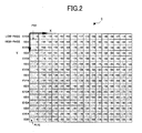
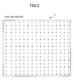
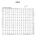
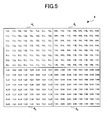
- FIGS. 2 through 5 are diagrams for illustrating a process of performing wavelet transform called a 5 ⁇ 3 transform employed in JPEG 2000 two-dimensionally (in the vertical and horizontal directions) on a 16 ⁇ 16 monochrome image.
- FIG. 2 is a diagram showing an original image and a coordinate system therefor.
- FIG. 3 is a diagram showing an array of coefficients after filtering in the vertical direction.
- FIG. 4 is a diagram showing an array of coefficients after filtering in the horizontal direction.
- FIG. 5 is a diagram showing an array of coefficients after rearrangement.
- JPEG 2000 provides two types of wavelet transform, that is, 5 ⁇ 3 wavelet transform and 9 ⁇ 7 wavelet transform. In the following description, only the 5 ⁇ 3 wavelet transform is given as an example of wavelet transform. The present invention, however, is also applicable to other wavelet transforms including the 9 ⁇ 7 wavelet transform.
- an X-Y coordinate plane is formed on the image with the horizontal direction being the X-axis, the vertical direction being the Y-axis, and the uppermost leftmost point being the origin.
- the pixel value of a pixel having a Y-coordinate value y for an X-coordinate value x is expressed as P( y ) (0 ⁇ y ⁇ 15).
- a pixel in the center may lack an adjacent pixel.
- an appropriate pixel value is supplemented in accordance with a predetermined rule, which is irrelevant to the essence of the present invention so that a description thereof will be omitted.
- a coefficient array 1 of FIG. 2 is converted to a coefficient array 2 of H and L coefficients as shown in FIG. 3 by the above-described vertical conversion.
- the coefficients obtained by performing low-pass filtering on the above-described coefficients L using its adjacent coefficients are expressed as LL
- the coefficients obtained by performing high-pass filtering on the above-described coefficients L using its adjacent coefficients are expressed as HL
- the coefficients obtained by performing low-pass filtering on the above-described coefficients H using its adjacent coefficients are expressed as LH
- the coefficients obtained by performing high-pass filtering on the above-described coefficients H using its adjacent coefficients are expressed as HH
- the coefficient array 2 of FIG. 3 is converted to a coefficient array 3 of FIG. 4.
- a group of coefficients assigned the same symbol (LL, for instance) is called a sub-band
- the image of FIG. 4 is composed of four sub-bands.
- the second wavelet transform operation may consider the LL sub-band 4 1 as an original image and perform the same conversion as described above.
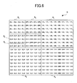
- a typical coefficient array 5 (of LL sub-band 5 1 , HL sub-band 5 2 , LH sub-band 5 3 , HH sub-band 5 4 , HL sub-band 4 2 , LH sub-band 4 3 , and HH sub-band 4 4 ) shown in FIG. 6 is obtained.
- FIG. 6 there exist seven types of sub-bands from 2LL to 1HH in total.
- the prefix of 1 or 2 to the coefficients indicates the number of wavelet transform operations by which the coefficients are obtained. This number is referred to as a decomposition level.
- the levels in FIG. 1 refer to the decomposition levels.
- a sub-band of a higher decomposition level has a lower resolution.
- wavelet transform in the case of performing wavelet transform only one-dimensionally, wavelet transform may be performed in either a horizontal or a vertical direction.
- a pixel in the center may lack an adjacent pixel.
- an appropriate pixel value is supplemented in accordance with a predetermined rule, which is irrelevant to the essence of the present invention so that a description thereof will be omitted.
- the coefficient array 3 of FIG. 4 is converted to the coefficient array 2, that is, the coefficient array 3 is inversely converted.
- This process is performed on each X-coordinate value x .
- one inverse wavelet transform operation is completed, so that the coefficient array 2 of FIG. 3 is returned to the coefficient array 1 of the image of FIG. 2.
- the coefficient array 1 of the original image is restructured.
- the same inverse wavelet transform operation may be repeated using the HL and other coefficients, considering the coefficient array 1 of FIG. 2 as the LL sub-band.
- a description of the way each sub-band is generated and restructured by wavelet transform and inverse wavelet transform will be given later (see FIG. 10).
- the result of inverse low-pass filtering is obtained from three coefficients including a coefficient of the filtering center (that is, a coefficient desired to be subjected to filtering), and it can also be understood that the result of inverse high-pass filtering is obtained from a coefficient of the filtering center and the two adjacent results of inverse low-pass filtering.
- the two results of inverse low-pass filtering are calculated from five coefficients including the coefficient of the filtering center. Therefore, the result of inverse high-pass filtering is obtained from five coefficients.
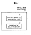
- FIG. 7 is a block diagram showing an image data generator 10 according to a first embodiment of the present invention.
- the image data generator 10 of this embodiment includes an inverse wavelet transform part 11 and a coefficient selecting part 12.
- the inverse wavelet transform part 11 performs inverse wavelet transform on wavelet coefficients obtained by performing wavelet transform on an original image one or a plurality of times, so that the image data generator 10 generates data on a size-reduced image of the original image.
- the original image includes an image obtained after performing conversion such as color conversion on the original image.
- the coefficient selecting part 12 selects those to be subjected to inverse wavelet transform of the coefficients in the same sub-band.
- all of the coefficients before selection can also be defined as all of the coefficients in one LL sub-band, which may be data on the original image. That is, the LL sub-band may be four sub-bands having a decomposition level higher than that of the LL sub-band by one.
- the selecting operation in this embodiment is different from the conventional technique of, for instance, selecting 2LL, 2HL, 2LH, and 2HH sub-bands but not selecting (that is, not performing inverse wavelet transform on) 1HL, 1LH, and 1HH sub-bands.
- the selecting operation can be performed more simply if the coefficients before selection are interleaved.
- the inverse wavelet transform part 11 performs inverse wavelet transform only on the coefficients selected by the coefficient selecting part 12 from the above-described wavelet coefficients in the same sub-band. Thereby, data on the size-reduced image is generated.
- the wavelet coefficients relating to other operations including an operation preceding the inverse wavelet transform such as coefficients in the 3LL sub-band (composed of 4LL, 4HL, 4LH, and 4HH sub-bands and not processed through the coefficient selecting part 12) to be obtained as required in the preceding operation may be inversely converted by the inverse wavelet transform part 11.
- the image data generator 10 includes a part selectively subjecting coefficients in the same or a single sub-band to inverse wavelet transform.
- the sub-band may be the entire original image.
- coefficients to be inversely converted (or subjected to inverse wavelet transform) by the inverse wavelet transform part 11 are referred to as wavelet coefficients or simply as coefficients.
- coefficients to be again inversely converted after being subjected to inverse wavelet transform are also referred to as wavelet coefficients or simply as coefficients.
- coefficients to be subjected to inverse wavelet transform in both directions and coefficients to be subjected to inverse wavelet transform in one direction are also referred to as wavelet coefficients or simply as coefficients.
- FIG. 8A is a diagram showing a 16 ⁇ 16 image generated by performing inverse wavelet transform on all of the coefficients obtained after performing 5 ⁇ 3 wavelet transform on the original image of FIG. 2.
- the size of the original image is defined as 16 ⁇ 16, and a 1/3 scale image, or an image reduced to one third of the original image vertically and horizontally in size, is generated from the original image as previously described in the first prior art and the second prior art.
- the 1/3 scale image is a 5 ⁇ 5 image since 16 is not divisible by three.
- FIG. 8A shows a coefficient array (equal to the coefficient array 1 of FIG. 2) of the 16 ⁇ 16 image generated by subjecting all of the coefficients to inverse wavelet transform first horizontally and then vertically.
- inverse wavelet transform may be performed centered only on the coefficients of the underlined pixels of all of the coefficients in FIG. 8A.
- This embodiment employs a 5 ⁇ 3 transform, so that the result of vertical inverse high-pass filtering can be obtained from a coefficient of the filtering center and its two adjacent results of inverse low-pass filtering. Therefore, finally, it is sufficient to (vertically) perform inverse wavelet transform only for the 45 shaded pixels in FIG. 8A.
- Pixels to be obtained in the case of employing a 5 ⁇ 3 transform and performing three-to-one scaling as in this embodiment are the 25 underlined pixels, so that at the preceding stage, that is, at the stage after performing horizontal filtering (before vertical filtering) at the time of an inverse wavelet transform operation, it is sufficient that only the 45 shaded pixels have been obtained.
- This embodiment employs a 5 ⁇ 3 transform, so that the result of vertical inverse high-pass filtering can be obtained from a coefficient of the filtering center and its two adjacent results of inverse low-pass filtering. Therefore, finally, it is sufficient to (vertically) perform inverse wavelet transform only for the 20 shaded pixels in FIG. 8B. This means that it is sufficient to select pixels equivalent to less than 8 % of the entire image and obtain the coefficients of the 20 pixels by vertical filtering at the time of an inverse wavelet transform operation.
- the coefficient selecting part 12 may include a part selecting at least all of the wavelet coefficients relating to the pixels of a size-reduced image to be generated (or desired to be finally obtained). Further, the coefficient selecting part 12 may include a part selecting only the wavelet coefficients relating to the pixels of a size-reduced image to be generated (or desired to be finally obtained). That is, inverse wavelet transform may be performed only on the wavelet coefficients relating to the pixels of a size-reduced image desired to be finally obtained.
- the term "relating" refers to a relationship originating from the nature of wavelet transform, such as a relationship derived from the above-described equations (1) through (4) (the shaded pixels to the underlined pixels in FIG. 8A). According to this configuration, a size-reduced image can be generated with the smallest amount of calculation.
- a finally obtained image as a result of performing inverse wavelet transform only on the coefficients relating to the pixels of a size-reduced image desired to be finally obtained is mathematically equivalent to a size-reduced image generated by thinning out or reducing an image obtained by performing inverse wavelet transform on all of the wavelet coefficients.
- a size-reduced image of the same size can be obtained.
- the inverse wavelet transform is performed using coefficients different from those obtained in the "forward" wavelet transform. Therefore, the obtained size-reduced image has no mathematical grounds.
- the coefficient selecting part 12 may include a part selecting, of the above-described wavelet coefficients in the same sub-band (in the interleaved state), all of the coefficients positioned on a straight line extending in one direction (in the vertical direction in the above-described case) in which inverse wavelet transform is performed finally, the straight line including a wavelet coefficient in a position of a pixel of a size-reduced image desired to be generated.
- FIG. 9A is a diagram showing a 16 ⁇ 16 image generated by performing horizontal filtering, at the time of an inverse wavelet transform operation, on all of the coefficients obtained after performing 5 ⁇ 3 wavelet transform on the original image of FIG. 1.
- a coefficient array 7 of FIG. 9A corresponds to the coefficient array 2 of FIG. 3.
- FIG. 9B is a diagram showing the 16 ⁇ 16 image of FIG. 9A in the case of obtaining its 5 ⁇ 4 image.
- the pixels of the shaded parts of FIG. 9A be selected as the coefficients in the state before horizontal filtering is performed at the time of an inverse wavelet transform operation.
- the 126 shaded pixels shown in FIG. 9A do not have the coefficients shown therein, which are obtained only after horizontal filtering at the time of an inverse wavelet transform operation.
- the actual application may also be simplified without making determination as to the "surrounding pixels" in the case of FIG. 9A.
- inverse wavelet transform may be performed two-dimensionally, and all of the coefficients positioned on straight lines perpendicular to the direction in which the first inverse wavelet transform in an inverse wavelet transform operation is performed may be obtained, the straight lines including the coefficients corresponding to the positions of the pixels of the size-reduced image and the positions relating to the positions of the pixels.
- the coefficient selecting part 12 of this embodiment may include a part that, at the time of selecting coefficients for inverse wavelet transform performed in one direction (in the horizontal direction in the above-described case) in which the inverse wavelet transform is performed first in an inverse wavelet transform operation, selects, of the above-described wavelet coefficients in the same sub-band (in the interleaved state), all of the coefficients on straight lines perpendicular to the direction in which the inverse wavelet transform is performed first, the straight lines including the coefficients corresponding to the positions of the pixels of the size-reduced image to be generated and the positions of pixels necessary for obtaining the positions of the pixels of the size-reduced image.
- the selected coefficients are subjected to inverse wavelet transform in the direction in which inverse wavelet transform is performed first, and are subjected to inverse wavelet transform in the other direction and thinned out as required.
- the coefficients of the pixel positions of the size-reduced image desired to be generated are obtained. According to this configuration, the actual application can be simplified in generating a size-reduced image.
- FIG. 10 is a diagram showing a configuration for generating a 1/3-resolution image along the flow of wavelet transform and inverse wavelet transform according to the present invention.
- the LL coefficients of a resolution lower than a desired resolution that is, the 2LL coefficients of a one-fourth resolution
- the obtained 2LL coefficients are selectively subjected to inverse wavelet transform using the coefficients of the 2HL, 2LH, and 2HH sub-bands, so that a 1/3-resolution image can be finally obtained.
- inverse wavelet transform may be performed on all of the coefficients of up to the resolution closest to a desired resolution. That is, the coefficient selecting part 12 of the present invention may include a part that selects all of the wavelet coefficients in the sub-bands of the same decomposition level higher than that of the LL sub-band having the highest resolution below the resolution of a size-reduced image to be obtained so that the LL sub-band is obtained by inverse wavelet transform.
- the number of adjacent pixels to be obtained differs depending on whether an underlined pixel desired to be finally obtained is located in an odd or even position. As previously described, this results from the difference in tap length between the low-pass filter and the high-pass filter. In this case, therefore, by selecting pixels desired to be finally obtained so that the desired pixels are located in even positions as much as possible, the number of adjacent pixels to be obtained can be minimized, so that processing can be performed at high speed.
- a vertex pixel of the pixels desired to be obtained that is, the pixel of -3 in FIG. 8A, may be located in an even position.
- the coefficients of pixels in such positions as to reduce the sum of the tap lengths of the filters may be selected.
- the tap length for inverse wavelet transform per direction becomes Tlow, namely, a minimum length.
- the, tap length for inverse wavelet transform per direction becomes Thigh, namely, a maximum length.
- the high-pass filter and the low-pass filter may have different tap lengths for inverse wavelet transform, so that the sum of the tap lengths of the high-pass and low-pass filters that perform filtering centered on the coefficients corresponding to the pixel positions of a size-reduced image to be .generated of all of the above-described coefficients in the same sub-band (in the interleaved state) is smaller than d ⁇ n(Tlow + Thigh)/2, where d is the dimensional number of inverse wavelet transform, n is the number of pixels of the size-reduced image, Tlow is the tap length of the low-pass filter, and Thigh is the tap length of the high-pass filter.
- processing can be performed at high speed in generating a size-reduced image by inverse wavelet transform.
- a step of performing inverse wavelet transform selectively on the coefficients in the same (or a single) sub-band, and a step of causing the sum of the tap lengths of the high-pass and low-pass filters to be smaller than n(Tlow + Thigh) the high-pass and low-pass filters having different tap lengths for inverse wavelet transform and performing filtering centered on the coefficients corresponding to the pixel positions of a size-reduced image of all of the coefficients in the interleaved state may be provided.
- processing can also be performed at high speed.
- the following processes (a) through (c) may be performed as main procedures to which the selective inverse wavelet transform of the present invention is applied.
- it may be determined based on the direction in which inverse wavelet transform is performed whether the selective inverse wavelet transform of the present invention is employed.
- RCT Reversible Component Transform
- FIG. 11 is a block diagram for illustrating an image data generator according to a second embodiment of the present invention and for illustrating a DWT (Discrete Wavelet Transform) image compression and decompression algorithm in JPEG 2000.
- DWT Discrete Wavelet Transform
- JPEG 2000 is an image compression and decompression method standardized internationally in 2001 as a successor to JPEG.
- the image data generator of FIG. 11 includes a two-dimensional wavelet transform and inverse transform part 22, a quantization and inverse quantization part 23, and an entropy coding and decoding part 24.
- the two-dimensional wavelet transform and inverse transform part 22 relates to the present invention.
- the two-dimensional wavelet transform and inverse transform part 22 is described mainly as an inverse wavelet transform part.
- the two-dimensional wavelet transform and inverse transform part 22, the quantization and inverse quantization part 23, and the entropy coding and decoding part 24 are provided as a part receiving an input from and transmitting an output to a color space conversion and inverse conversion part 21 and a tag processing part 25.
- Each of these parts may have independent configurations for the forward (compression) and inverse (decompression) operations. Further, each of these parts may perform processing component by component.
- the wavelet coefficients of each of the components obtained through entropy decoding and inverse quantization are subjected to inverse wavelet transform. Thereafter, the wavelet coefficients are subjected to color conversion so as to be returned to the R, G, and B pixel values.
- the color-difference components are more quantized in the quantization process of FIG. 11 than the luminance component because, generally, luminance has a greater effect than color difference.
- an apparatus for generating a size-reduced image of an original image by performing inverse wavelet transform on the wavelet coefficients of a plurality of components may include a part that performs inverse wavelet transform on the components to different resolutions so that the resolution differs between the components when inverse wavelet transform is performed. That is, inverse wavelet transform may be performed with a difference between the resolutions of the components.
- the image data generator of this embodiment may be an apparatus for generating data on a size-reduced image of an original image, the apparatus including an inverse wavelet transform part that performs inverse wavelet transform on the wavelet components of a plurality of components.
- the inverse wavelet transform part performs inverse wavelet transform component by component with the resolution differing between at least one of the components and the rest of the components. According to this embodiment, a size-reduced image formed of a plurality of components can be generated at high speed with a reduced amount of processing using the characteristic between the components.
- the coefficients of the LL sub-band having the highest resolution below the resolution of a size-reduced image to be generated may be obtained. According to this configuration, a size-reduced image formed of a plurality of components can be generated at higher speed with more simplicity.
- the above-described components may be a luminance component and a color-difference component, and the luminance component is subjected to inverse wavelet transform to a resolution higher than a resolution to which the color-difference component is subjected to inverse wavelet transform.
- the color-difference component has a lower resolution. According to this configuration, a size-reduced image formed of luminance and color-difference components can be generated at higher speed with a reduced amount of processing while the effect on image quality is controlled.
- the above-described components may include two color-difference components, and the two color-difference components may be subjected to inverse wavelet transform to different resolutions.
- a size-reduced image formed of a plurality of components may be generated at higher speed by setting a lower resolution for one of the color-difference components than for the other one of the color-difference components, using the characteristic between the color-difference components.
- the resolution of the color-difference components may be set to a half of the resolution of the luminance component.
- this resolution combination which corresponds to sub-sampling color difference to one-fourth of luminance, provides a good balance between image quality and processing speed.
- a size-reduced image formed of a plurality of components can be generated with image quality and processing speed being in balance with each other.
- the present invention can also be realized as: an image data generating method including the processing steps performed in the image data generators; a program for causing a computer to function as any of the above-described image data generators or as each part thereof or a program for causing a computer to execute the image data generating method (a computer program with the contents of the processing steps); and a computer-readable recording medium recording the program (a computer-readable information recording medium recording the contents of the processing steps).
- this image data generating method of the present invention a size-reduced image can be generated with a reduced amount of calculation and/or a size-reduced image can be generated at high speed using the characteristics between components. Further, this program makes it possible to provide a system that can generate a size-reduced image with a reduced amount of calculation, can generate a size-reduced image simply with high image quality, and can generate a size-reduced image at high speed using the characteristics between components by the operations corresponding to the above-described embodiments.
- this recording medium makes it possible to provide a system that can generate a size-reduced image with a reduced amount of calculation, can generate a size-reduced image simply with high image quality, and can generate a size-reduced image at high speed using the characteristics between components with the configurations corresponding to the above-described embodiments. It is apparent that this program and this recording medium can be realized easily based on the later-described embodiment in addition to the above-described embodiments.
- the recording medium may be any of a CD-ROM, a magneto-optical disk, a DVD-ROM, a FD, a flash memory, and other various ROMs and RAMs.
- the recording medium is recorded with a program for causing a computer to execute the functions relating to the above-described embodiments according to the present invention so as to realize the image data generating function of the present invention.
- the image data generating function according to the present invention can be performed by loading the recording medium into an information processing apparatus such as a computer and causing the information processing apparatus to read out the program or by storing the program in a recording medium provided in an information processing apparatus and reading out the program as required.
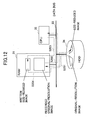
- FIG. 12 is a block diagram showing an image data generator according to the third embodiment of the present invention.
- a RAM 31, a CPU 32, and an HDD 34 are connected via a data bus 33.
- a size-reduced image is generated from a compressed image of an original resolution and stored in the HDD 34 in the following process.
- step S201 compressed image data of an original resolution recorded on the HDD 34 is read into the RAM 31 by a command transmitted from the CPU 32.
- step S202 the CPU 32 reads the compressed image data recorded in the RAM 31 only for an amount corresponding to a predetermined resolution, and obtains wavelet coefficients.
- the CPU 32 performs processing on the wavelet coefficients according to the present invention, thereby generating a size-reduced image.
- step S203 the CPU 32 writes the generated size-reduced image to another region in the RAM 31.
- step S204 the size-reduced image is recorded on the HDD 34 by a command transmitted from the CPU 32.
- FIG. 13 is a block diagram showing another image data generator according to the third embodiment of the present invention.
- a RAM 35 inside a personal computer (PC), a CPU 36 inside the PC, an HDD 38, and a monitor 39 such as a CRT or LCD monitor are connected via a data bus 39.
- a size-reduced image is generated at high speed from image data of an original resolution and displayed on the monitor 39.
- step S211 compressed image data of an original resolution recorded on the HDD 38 is read into the RAM 35 by a command transmitted from the CPU 36.
- step S212 the CPU 36 reads the compressed image data recorded on the RAM 35 only for an amount corresponding to a predetermined resolution, and obtains wavelet coefficients. Then, the CPU 36 performs processing on the wavelet coefficients according to the present invention, thereby generating a size-reduced image.
- step S213 the CPU 36 writes the generated size-reduced image to another region in the RAM 35.
- step S214 the size-reduced image is transmitted to and displayed on the monitor 39 by a command transmitted from the CPU 36.
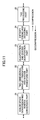
- FIG. 14 is a flowchart for illustrating the basic flow of an operation of generating a size-reduced image in an image data generator according to a fourth embodiment of the present invention.
- FIG. 15 is a diagram showing a code configuration according to the fourth embodiment of the present invention.
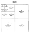
- FIG. 16 is a diagram showing the relationship between decomposition level and resolution level according to the fourth embodiment of the present invention.
- step S1 the resolution level of a size-reduced image to be generated is set to (resolution level) r based on a resolution (1/k) specified by a user. It is preferable that the image data generator include a part that allows the user to specify a desired resolution. Then, in step S2, (resolution level) i is set to zero. In steps S3 through S5, i is incremented until i reaches r . During this process, in step S4, the entropy codes of all components are decoded with respect to each resolution level i .
- the decoding of the entropy codes is the decoding of variable length codes, and an MQ-coder is employed for the decoding in JPEG 2000. Since the decoding of the entropy codes is irrelevant to the point of this embodiment, a description thereof will be omitted.
- FIG. 15 shows the codes of the components arranged in the following order: component 0 (luminance), component 1 (color difference Cb), and component 2 (color difference Cr) of resolution 0 (minimum resolution), components 0, 1, and 2 of resolution 1, components 0, 1, and 2 of resolution 2, ....
- component 0 luminance
- component 1 color difference Cb
- component 2 color difference Cr
- FIG. 16 shows the relationship between decomposition level and resolution level.
- Each "LL" sub-band takes an exceptional value in this relationship. That is, the resolution level of 3LL is resolution level 0, the resolution level of 3HL, 3LH, and 3HH is resolution level 1, the resolution level of 2HL, 2LH, and 2HH is resolution level 2, and the resolution level of 1HL, 1LH, and 1HH is resolution level 3. Further, the resolution level of 2LL is resolution level 1, and the resolution level of 1LL is resolution level 2.
- the value of r is calculated by the equation (7) to be set in step S1.
- the resolution of the size-reduced image is specified by a user as 1/kh horizontally and 1/kv vertically with respect to the original image, the smaller of kh and kv is defined as k .
- r is calculated by the equation (7) to be set in step S1, so that the operation of FIG. 14 is performed.
- step S6 the inversely quantized wavelet coefficients are subjected to a selected inverse wavelet transform operation.
- the selected inverse wavelet transform operation of step S7 which forms an important part of the present invention, is composed of an LL generating operation performed shown in FIG. 17, a horizontal pixel position determining and horizontal filtering operation performed shown in FIG.
- step S8 an inverse color conversion operation is performed when there are two or more components.
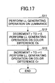
- FIG. 17 is a flowchart for illustrating the LL generating operation performed on each component according to the fourth embodiment of the present invention.
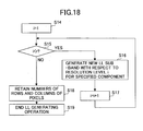
- FIG. 18 is a flowchart for illustrating the operation of FIG. 17 in detail.
- FIG. 18 illustrates an operation of obtaining the coefficients of an LL sub-band having a resolution lower than that of a size-reduced image to be generated.
- step S11 of FIG. 17 the LL generating operation is performed on the luminance Y.
- the resolution of luminance is reduced in the ratio of k : 1
- the resolution of Cr and the resolution of Cb are reduced in the ratio of 2k : 1 and 4k : 1, respectively.
- k in FIGS. 20 and 22 are treated as 2k and 4k, respectively.
- step S16 with respect to each resolution level i , using an LL sub-band and three HL, LH, and HH sub-bands of resolution level i, inverse wavelet transform is performed to generate a new LL sub-band for a specified component.
- step S18 the number of vertical pixels (rows) LLheight and the number of horizontal pixels (columns) LLwidth of the new LL sub-band are retained.
- step S19 the LL generating operation ends. Thereby, all of the wavelet coefficients of the LL sub-band having the highest resolution below the resolution of a size-reduced image to be generated are obtained.
- the LL sub-band is generated using the sub-bands of up to a resolution level lower than that of the luminance Y by two.
- the LL sub-band is generated using the sub-bands of up to a resolution level higher than that of the color difference Cb by one.
- the resolution of the color difference Cr is set to a half of the resolution of the luminance Y.
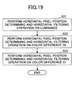
- FIG. 19 is a flowchart for illustrating the horizontal pixel position determining and horizontal filtering operation performed on each component according to the fourth embodiment of the present invention.
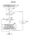
- FIG. 20 is a flowchart for illustrating the operation of FIG. 19 in detail.
- step S21 of FIG. 19 the horizontal pixel position determining and horizontal filtering operation is performed on the luminance Y.
- step S22 the horizontal pixel position determining and horizontal filtering operation is performed on the color difference Cb.
- step S23 the horizontal pixel position determining and horizontal filtering operation is performed on the color difference Cr.
- FIG. 20 shows the operation of obtaining the maximum value p of 2 n smaller than k , obtaining the horizontal positions of the above-described "pixels desired to be finally obtained" with k/p being employed as a unit (a horizontal position determining operation), and performing horizontal filtering on all of the vertical positions of each of the horizontal positions.
- horizontal filtering is performed on all of the vertical positions, the wavelet coefficients can be selected so as to be selectively subjected to inverse wavelet transform. This is because the horizontal position determining operation is performed. That is, according to'the horizontal pixel position determining and horizontal filtering operation, first, in step S24 of FIG. 20, the maximum value p of 2 n smaller than k is obtained based on the resolution 1/k specified by the user.
- . Thereafter, in steps S27 and S28, i is incremented until xs equals 2 ⁇ LLwidth (xs 2 ⁇ LLwidth), while step S26 is performed. During this process, in step S29, horizontal filtering is performed on all of the vertical positions of each column whose X-coordinate value is xs. If the result of step S27 is "NO", the operation ends.
- the value of r is calculated by the equation (7) using the smaller of kh and kv as k .
- the number of adjacent pixels to be obtained can be reduced by first selecting (0, 0) of FIG. 2, that is, a horizontally and vertically even-numbered position, as the "vertex pixel of the pixels desired to be finally obtained" of each component.
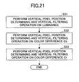
- FIG. 21 is a flowchart for illustrating the vertical pixel position determining and vertical filtering operation performed on each component according to the fourth embodiment of the present invention.
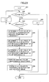
- FIG. 22 is a flowchart for illustrating the operation of FIG. 21 in detail.
- step S31 the vertical pixel position determining and vertical filtering operation is performed on the luminance Y.
- step S32 the vertical pixel position determining and vertical filtering operation is performed on the color difference Cb.
- step S33 the vertical pixel position determining and vertical filtering operation is performed on the color difference Cr.
- the vertical pixel position determining and vertical filtering operation which is similar to the horizontal pixel position determining and horizontal filtering operation of FIGS. 19 and 20, is performed only on necessary pixel positions.
- step S49 each pixel value after the filtering is stored in the position (i, j) in a buffer for reduced component. Thereafter, as previously described, step S47 is performed.
- step S47 is performed.
- the operation of obtaining xs may be omitted. In this case, the vertical filtering is performed with respect to each horizontal position (column).
- in step S42 and the vertical position ys is determined by ys
- FIG. 23 is a diagram for illustrating the inverse color conversion operation according to this embodiment.
- the maximum value of the decomposition level and the number of vertical pixels (height) and the number of horizontal pixels (width) of an original image can be read from the headers of the codes, and the number of vertical pixels and the number of horizontal pixels of a size-reduced image to be finally generated are given by
- the color difference components are subjected to inverse wavelet transform only up to resolutions lower than that of the luminance component by one or more levels. Therefore, the number of pixels of the size-reduced image to be generated is defined by the following:
- the number of pixels of the size-reduced image to be generated is defined by the following:
- step S55 In the inverse color conversion operation, if i ⁇
- with j being set to zero ( j 0). During this operation, below-described operations are performed, and if it is determined in step S52 that i ⁇
- the operations performed during the above-described operation are as follows.
- step S53 steps S55 through S59 are performed until j equals
- (that is, "NO” in step S53), i is incremented and j is set to zero ( j 0), and the operation returns to step S52.
- step S55 with respect to the luminance Y, Y is determined to be the value of the position (i, j) in the buffer for reduced component of the luminance Y.
- step S56 with respect to the color difference Cb, Cb is determined to be the value of the position (i/4, j/4) in the buffer for reduced component of the color difference Cb.
- step S57 with respect to the color difference Cr, Cr is determined to be the value of the position (i/2, j/2) in the buffer for reduced component of the color difference Cr.
- step S58 inverse color conversion is performed by the above-described equations (6), and in step S59, the R, G, and B values are stored in the position (i, j) in a buffer for size-reduced image.
- the wavelet coefficients of up to an LL sub-band (and HL, LH, and HH sub-bands) that may be interleaved to have a resolution (or pixels) half the resolution (or pixels) of the original image are obtained, and the 2/3-resolution image of the interleaved coefficients of the LL sub-band is generated by the processing of the present invention.
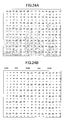
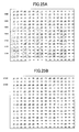
- FIGS. 24A and 25A are diagrams showing pixels to be obtained in the case of generating the 2/3-resolution image of the interleaved coefficients.
- FIG. 24A those pixels in the state after horizontal filtering at the time of an inverse wavelet transform operation are indicated by shading.
- FIG. 25A those pixels in the state after vertical filtering at the time of the inverse wavelet transform operation are indicated by shading.
- FIGS. 24A and 25A the pixels to be finally obtained are shown underlined as in FIG. 8A.
- a coefficient array 8 of FIG. 24A and a coefficient array 9 of FIG. 25A as in FIGS.
- FIGS. 24A and 25A show pixels to be obtained in the case of generating a 10 ⁇ 8 image of the 16 ⁇ 16 interleaved coefficients (sub-band).
- FIG. 24B the coefficient positions to be subjected to horizontal inverse wavelet transform are indicated by shading
- FIG. 25B the coefficient positions to be subjected to vertical inverse wavelet transform are indicated by shading.
- Decoding is often employed in generating a size-reduced image to be displayed on a display unit having a small screen.
- the display unit is limited in representation performance, the image quality of the size-reduced image itself may not be strictly questioned. Rather, decoding time may become an issue. Further, due to the limited representation performance of the display unit, the degradation of data on the size-reduced image often cannot be observed visually.
- the entropy decoding of wavelet coefficients can be performed at high speed by limiting the code-decoding ratio.
- code-decoding ratio the ratio of codes to be decoded
- the binary representation of a wavelet coefficient is decoded bit by bit from MSB (Most Significant Bit) to LSB (Least Significant Bit)
- decoding image quality and decoding speed can be optimized by selecting an appropriate bit up to which the decoding is to be performed.
- FIG. 26 is a block diagram showing an image data generator 40 according to this embodiment.
- the image data generator 40 which generates data on a size-reduced image of an original image, includes a coefficient decoding part 41 decoding coded wavelet coefficients and a code omitting part 42.
- the code omitting part 42 omits, of the codes of the same sub-band, the codes that are not to be decoded.
- the coefficient decoding part 41 decodes the codes other than those omitted in the code omitting part 42. That is, the coefficient decoding part 41 decodes part of the codes of the same sub-band.
- the image data generator 40 may decode part of a layer and obtain a size-reduced image based on the decoded data. According to this embodiment, it is possible to generate size-reduced data, balancing decoding speed and decoded image quality.
- the partial decoding according to the present invention excludes the case of performing no decoding, which case is equivalent to the case of omitting decoding by band restriction.
- the sub-bands may be provided with different code-decoding ratios. That is, the amount or ratio of codes to be omitted (not to be decoded) in the code omitting part 42 may be caused to differ among the sub-bands. According to this configuration, by considering the effect on image quality by each sub-band, a size-reduced image can be generated with decoding speed and decoded image quality being optimized.
- the LL, HL, LH, and HH sub-bands may be provided with different code-decoding ratios. That is, the amount or ratio of codes to be omitted in the code omitting part 42 may be caused to differ among the sub-bands of the same decomposition level. According to this configuration, by considering the effect on image quality by each of the sub-bands of the same decomposition level, a size-reduced image can be generated with decoding speed and decoded image quality being optimized.
- the decomposition levels may be provided with different code-decoding ratios. That is, the amount or ratio of codes to be omitted in the code omitting part 42 may be caused to differ among the decomposition levels. According to this configuration, by considering the effect on image quality by each decomposition level, a size-reduced image can be generated with decoding speed and decoded image quality being optimized.
- R G + Cr
- B Cb + G
- represents a floor function of x that replaces a real number x with the largest of all the integers smaller than or equal to x.
- the components may be provided with different code-decoding ratios. That is, decoding may be performed component by component, and the amount or ratio of codes to be omitted in the code omitting part 42 may be caused to differ among the components. According to this configuration, by considering the effect on image quality by each component, a size-reduced image can be generated with decoding speed and decoded image quality being optimized.
- the LL sub-band may be provided with the smallest amount or ratio of codes not to be decoded. According to this configuration, by considering the effect on image quality by the LL sub-band, a size-reduced image can be generated with decoding speed and decoded image quality being optimized.
- the HH sub-band may be provided with the largest amount or ratio of codes not to be decoded. According to this configuration, by considering the effect on image quality by the HH sub-band, a size-reduced image can be generated with decoding speed and decoded image quality being optimized.
- a higher decomposition level may be provided with a smaller amount or ratio of codes not to be decoded. According to this configuration, by considering the effect on image quality by the decomposition level, a size-reduced image can be generated with decoding speed and decoded image quality being optimized.
- the luminance component in an apparatus decoding a luminance component, may be provided with the smallest amount or ratio of codes not to be decoded of all components. According to this configuration, by considering the effect on image quality by luminance, a size-reduced image can be generated with decoding speed and decoded image quality being optimized.
- the color-difference components may be provided with different amounts or ratios of codes not to be decoded. According to this configuration, by considering the effect on image quality by each color-difference component, a size-reduced image can be generated with decoding speed and decoded image quality being optimized.
- Y ⁇ Cr ⁇ Cb may hold in terms of the amount or ratio of codes not to be decoded. It is empirically known that in light of human visual characteristics, Cb has a smaller effect than Cr. According to this configuration, by considering the effect on image quality by each of Cb and Cr, a size-reduced image can be generated with decoding speed and decoded image quality being optimized.
- codes are decoded to a size larger than the desired size and thinned out after being subjected to inverse wavelet transform, or codes are decoded to a size smaller than the desired size and subjected to interpolation.
- the code-decoding ratio should be set higher in the latter case (with interpolation processing) than in the former case (with thinning-out processing).
- the image data generator 40 of this embodiment may include a part decoding only a sub-band of a size smaller than or equal to a desired image size.
- the codes are extracted in the size of an LL sub-band. According to this configuration, by restricting the size of a sub-band to be decoded, a size-reduced image can be generated with decoding speed and decoded image quality being optimized.
- the image data generator 40 of this embodiment may include a part decoding only a sub-band of a size smaller than a desired image size and a part thinning out the decoded sub-band. According to this configuration, by restricting the size of a sub-band to be decoded, a size-reduced image can be generated with decoding speed and decoded image quality being optimized.
- the image data generator 40 of this embodiment may include a part decoding sub-bands of up to the maximum of sizes smaller than or equal to a desired image size and a part performing interpolation. According to this configuration, by restricting the size of a sub-band to be decoded, a size-reduced image can be generated with decoding speed and decoded image quality being optimized.
- the above description is given, focusing on the image data generator performing the partial decoding of the present invention.
- the present invention may also be realized as: an image data generating method including the processing steps performed in the image data generator; a program for causing a computer to function as the above-described image data generator or as each part thereof or a program for causing a computer to execute the image data generating method (a computer program with the contents of the processing steps); and a computer-readable recording medium recording the program (a computer-readable information recording medium recording the contents of the processing steps).
- an image data generating method of the present invention a size-reduced image can be generated with decoding speed and decoded image quality being balanced or optimized.
- this program makes it possible to provide a system that can generate a size-reduced image, balancing or optimizing decoding speed and decoded image quality, by the operations corresponding to the above-described embodiment.
- this recording medium makes it possible to provide a system that can generate a size-reduced image, balancing or optimizing decoding speed and decoded image quality, with the configurations corresponding to the above-described embodiment. It is apparent that this program and this recording medium can be realized easily based on the later-described embodiment in addition to the above-described embodiment.
- the recording medium may be any of a CD-ROM, a magneto-optical disk, a DVD-ROM, a FD, a flash memory, and other various ROMs and RAMs.
- the recording medium is recorded with a program for causing a computer to execute the functions relating to the above-described embodiment according to the present invention so as to realize the image data generating function of the present invention.
- the image data generating function according to the present invention can be performed by loading the recording medium into an information processing apparatus such as a computer and causing the information processing apparatus to read out the program or by storing the program in a recording medium provided in an information processing apparatus and reading out the program as required.
- the amount or ratio of codes not to be decoded in the partial decoding operation of the present invention means, for instance, the "number of bit planes not to be decoded” or the “number of bit planes not to be decoded against the total number of coded bit planes.”
- JPEG 2000 selecting the 5 ⁇ 3 wavelet transform is employed. Therefore, a description will first be given of the outline of the JPEG 2000 operation.
- the application range of the present invention is not limited to JPEG 2000.
- the rightward arrow ( ⁇ ) and the leftward arrow ( ⁇ ) in the JPEG 2000 encoding and decoding processes indicate the direction of encoding (compression) and the direction of decoding (decompression), respectively.
- FIG. 11 shows that at the time of decoding, the wavelet coefficients of each component obtained through entropy decoding and inverse quantization (as required) are subjected component by component to inverse wavelet transform and then inverse color conversion to be returned to the R, G, and B pixel values.
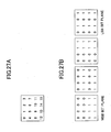
- FIG. 27A is a diagram showing the coefficients of a 2LL sub-band
- FIG. 27B is a diagram showing the coefficients divided into bit planes.
- FIG. 28 is a diagram showing a code configuration according to the sixth embodiment. FIG. 28 shows that codes can be arranged in the order the codes are arranged from top to bottom in FIG. 28.
- the coefficients of the 2LL sub-band 5 1 of FIG. 6 take the values shown in FIG. 27A. These values are expressed in binary numbers and the binary numbers of the same digit position are grouped into a bit plane.
- the coefficients of FIG. 27A can be divided into the four bit planes of FIG. 27B.
- the decimal number 15 is expressed as a binary 1111, so that a binary 1 occupies the position corresponding to 15 in each bit plane.
- each bit plane is individually coded. That is, it is possible to generate codes with the configuration of FIG. 28.
- FIG. 28 shows that the codes start from the 2LL sub-band and end at the 1HH sub-band.
- the bit planes are coded in order from the MSB bit plane to the LSB bit plane, and the decoder can recognize the total number of coded bit planes. Therefore, the decoder can easily omit the decoding of the LSB bit plane or the decoding of the two bit planes counted from the LSB bit plane.
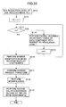
- FIG. 29 is a flowchart for illustrating the basic flow of the size-reduced image generating operation performed in an image data generator according to the sixth embodiment of the present invention.
- FIGS. 30 through 32 are flowcharts for expatiating the partial decoding in the operation of FIG. 29, showing the partial decoding in the luminance component Y, the color difference component Cr, and the color difference component Cb, respectively.
- FIG. 28 shows the codes of the components arranged in the following order: component 0 (luminance), component 1 (color difference V), and component 2 (color difference U) of resolution 0 (minimum resolution), components 0, 1, and 2 of resolution 1, components 0, 1, and 2 of resolution 2, ....
- component 0 luminance
- component 1 color difference V
- component 2 color difference U
- resolution 0 minimum resolution
- components 0, 1, and 2 of resolution 1 components 0, 1, and 2 of resolution 2, ....
- the codes of all components can be arranged in the order of resolutions as shown in FIG. 28. Therefore, it is possible to extract only the wavelet coefficients from the lowest resolution up to a desired resolution with ease (steps S71 through S75).
- FIG. 16 shows the relationship between decomposition level and resolution level.
- Each "LL" sub-band takes an exceptional value in this relationship. That is, the resolution level of 3LL is resolution level 0, the resolution level of 3HL, 3LH, and 3HH is resolution level 1, the resolution level of 2HL, 2LH, and 2HH is resolution level 2, and the resolution level of 1HL, 1LH, and 1HH is resolution level 3. Further, the resolution level of 2LL is resolution level 1, and the resolution level of 1LL is resolution level 2.
- the value of r is calculated by the equation (7) to be set in step S71.
- step S76 when the decoding is completed in each resolution level i lower than resolution level r (that is, "NO" in step S73), in step S76, all of the decoded wavelet coefficients are inversely quantized. Thereafter, in step S77, the inversely quantized wavelet coefficients are subjected to an inverse wavelet transform operation.
- the above-described selected inverse wavelet transform operation may be applied as the inverse wavelet transform operation of step S77.
- step S78 it is determined whether i equals r .
- step S79 thinning-out processing is performed.
- i that is, "YES” in step S78
- step S80 inverse color conversion is performed and the operation ends.
- Partial decoding which is one feature of the present invention, is the operation of step S74.
- the wavelet coefficients of each component are obtained by partially decoding the codes of each component in the following manner, depending on the value of i of the resolution level (or depending on the decomposition level).
- step S81 it is determined whether the component is the luminance Y. If the component is other than the luminance Y, the operation of FIG. 31 or 32 is started. With respect to the luminance Y (that is, in the case of "YES" in step S81), in step S82, it is determined whether i ⁇ r-2 is satisfied, and in step S84, it is determined whether i ⁇ r-1 is satisfied. Based on the results of determination of these steps, the codes of the luminance Y are partially decoded so that the wavelet coefficients of the luminance Y are obtained.
- step S83 the codes of all of the bit planes are decoded with respect to each sub-band. Since the LL sub-band exists only at resolution level 0, all of the codes of the LL sub-band are decoded as a result of step S83, so that the amount of codes not to be decoded is minimized.
- step S85 decoding is performed on the bit planes of the sub-bands except for the two bit planes counted from the LSB bit plane (that is, the LSB bit plane and the next low-order bit plane) with respect to the HL and LH sub-bands and the three bit planes counted from the LSB bit plane with respect to the HH sub-band.
- step S86 decoding is performed on the bit planes of the sub-bands except for the three bit planes counted from the LSB bit plane with respect to the HL and LH sub-bands and the four bit planes counted from the LSB bit plane with respect to the HH sub-band.
- step S91 of FIG. 31 it is determined whether the component is the color difference Cr. If the component is other than the color difference Cr, the operation of FIG. 32 (or 30) is started. With respect to the color difference Cr (that is, in the case of "YES" in step S91), in step S92, it is determined whether i ⁇ r-3 is satisfied, in step S94, it is determined whether i ⁇ r-2 is satisfied, and in step S96, it is determined whether i ⁇ r-1 is satisfied. Based on the results of determination of these steps, the codes of the color difference Cr are partially decoded so that the wavelet coefficients of the color difference Cr are obtained. With respect to the codes of the color difference Cr, the wavelet coefficients are obtained by further omitting the decoding of one more bit plane than with respect to the codes of the luminance Y.
- step S93 the codes of all of the bit planes are decoded with respect to each sub-band.
- step S95 decoding is performed on the bit planes of the sub-bands except for the two bit planes counted from the LSB bit plane with respect to the HL and LH sub-bands and the three bit planes counted from the LSB bit plane with respect to the HH sub-band.
- step S97 decoding is performed on the bit planes of the sub-bands except for the three bit planes counted from the LSB bit plane with respect to the HL and LH sub-bands and the four bit planes counted from the LSB bit plane with respect to the HH sub-band.
- step S98 decoding is performed on the bit planes of the sub-bands except for the four bit planes counted from the LSB bit plane with respect to the HL and LH sub-bands and the five bit planes counted from the LSB bit plane with respect to the HH sub-band.
- step S101 of FIG. 32 it is determined whether the component is the color difference Cb. If the component is other than the color difference Cb, the operation of FIG. 30 or 31 is started. With respect to the color difference Cb (that is, in the case of "YES" in step S101), in step S102, it is determined whether i ⁇ r-3 is satisfied, in step S104, it is determined whether i ⁇ r-2 is satisfied, and in step S106, it is determined whether i ⁇ r-1 is satisfied. Based on the results of determination of these steps, the codes of the color difference Cb are partially decoded so that the wavelet coefficients of the color difference Cb are obtained. With respect to the codes of the color difference Cb, the wavelet coefficients are obtained by further omitting the decoding of one more bit plane than with respect to the codes of the color difference Cr.
- step S103 the codes of all of the bit planes are decoded with respect to each sub-band.
- step S105 decoding is performed on the bit planes of the sub-bands except for the three bit planes counted from the LSB bit plane with respect to the HL and LH sub-bands and the four bit planes counted from the LSB bit plane with respect to the HH sub-band.
- step S107 decoding is performed on the bit planes of the sub-bands except for the four bit planes counted from the LSB bit plane with respect to the HL and LH sub-bands and the five bit planes counted from the LSB bit plane with respect to the HH sub-band.
- step S108 decoding is performed on the bit planes of the sub-bands except for the five bit planes counted from the LSB bit plane with respect to the HL and LH sub-bands and the six bit planes counted from the LSB bit plane with respect to the HH sub-band.
- Y ⁇ Cr ⁇ Cb holds among the components in terms of the amount of codes not to be decoded. Further, the amount of codes not to be decoded is smaller at a higher decomposition level. When each sub-band has the same total number of coded bit planes, the amount of codes not to be decoded is directly equal to the ratio of codes not to be decoded.
- an MQ-coder is employed as an entropy coder.
- the resolution level of wavelet transform is higher than the resolution specified by the user. Therefore, in step S79, each of Y, Cr, and Cb is converted to a desired size by well-known thinning-out processing after being subjected to inverse quantization and inverse wavelet transform.
- thinning-out processing is performed before inverse color conversion instead of thinning out the R, G, and B values obtained after inverse color conversion.
- Omitting the decoding of the LSB bit plane is equivalent to dividing (quantizing) the wavelet coefficients by two. Omitting the decoding of the n bit planes counted from the LSB bit plane is equivalent to quantizing the wavelet coefficients by 2 n . Therefore, in the case of omitting the decoding of bit planes, multiplying the decoded wavelet coefficients by 2 n is equivalent to performing inverse quantization on the decoded wavelet coefficients.
- the equations (8) are employed to calculate Y, Cr, and Cb.
- the technique of this embodiment is also applicable.
- the nearest neighbor method which is widely used, is taken as an example of thinning-out processing. Since the algorithm of thinning-out processing itself does not affect the theme of the partial decoding of the present invention, an expatiation of the algorithm will be omitted. For the details of the algorithm, "Introduction to Computer Image Processing" (by Hideyuki Tamura, Soken Publishing Ltd., 1985) may be referred to.
- FIG. 33 is a flowchart for illustrating the basic flow of another size-reduced image generating operation performed in the image data generator according to this embodiment to which method the partial decoding of the present invention is applied.
- step S73 the conditional expression of step S73 is i ⁇ r . Therefore, the resolution level of the extracted wavelet coefficients is equal to or higher by one than the resolution specified by the user. If the conditional expression of step S73 is changed to i ⁇ r , however, the resolution level lower than the resolution level specified by the user by one can be extracted, so that each of Y, Cr, and Cb is converted to a desired size by well known interpolation processing after being subjected to inverse wavelet transform.
- step S116 when the decoding is completed in each resolution level i lower than resolution level r (that is, "NO" in step S113), in step S116, all of the decoded wavelet coefficients are inversely quantized. Thereafter, in step S117, the inversely quantized wavelet coefficients are subjected to an inverse wavelet transform operation.
- the above-described selected inverse wavelet transform operation may be applied as the inverse wavelet transform operation of step S117.
- step S118 interpolation is performed.
- the nearest neighbor method which is widely used, is taken as an example of interpolation. For the expatiation of the algorithm of interpolation, the above-described "Introduction to Computer Image Processing" may be referred to.
- step S119 inverse color conversion is performed and the operation ends.
- the wavelet coefficients are subjected to inverse wavelet transform, and in the case of generating a size-reduced image of an original image, the wavelet coefficients in the same sub-band are selectively subjected to inverse wavelet transform. Therefore, the size-reduced image can be generated with a reduced amount of calculation.
- the wavelet coefficients in the same sub-band are partially decoded in performing inverse wavelet transform on the wavelet coefficients and generating a size-reduced image of an original image. Therefore, the size-reduced image can be generated with decoding speed and decoded image quality being balanced with each other.
Landscapes
- Physics & Mathematics (AREA)
- General Physics & Mathematics (AREA)
- Engineering & Computer Science (AREA)
- Theoretical Computer Science (AREA)
- Editing Of Facsimile Originals (AREA)
- Compression Or Coding Systems Of Tv Signals (AREA)
- Compression Of Band Width Or Redundancy In Fax (AREA)
- Image Processing (AREA)
Abstract
Description
Claims (24)
- An image data generator for generating data on a size-reduced image of an original image, the image data generator including an inverse wavelet transform part performing inverse wavelet transform on wavelet coefficients, characterized by:a coefficient selecting part selecting, of wavelet coefficients in a sub-band, wavelet coefficients to be subjected to the inverse wavelet transform,the image data generator being characterized in that said inverse wavelet transform part performs the inverse wavelet transform only on the wavelet coefficients selected in said coefficient selecting part with respect to the wavelet coefficients in the sub-band.
- The image data generator as claimed in claim 1, characterized in that said coefficient selecting part comprises a part selecting at least all of wavelet coefficients relating to pixels of the size-reduced image to be generated.
- The image data generator as claimed in claim 1, characterized in that said coefficient selecting part comprises a part selecting only wavelet coefficients relating to pixels of the size-reduced image to be generated.
- The image data generator as claimed in any of claims 1 to 3, characterized in that:the inverse wavelet transform comprises a plurality of inverse wavelet transforms; andsaid coefficient selecting part comprises a part selecting, of the wavelet coefficients in the sub-band in an interleaved state, all of wavelet coefficients positioned on straight lines extending in a direction in which the last one of the inverse wavelet transforms is performed, the straight lines each including a wavelet coefficient corresponding to a pixel position of the size-reduced image to be generated.
- The image data generator as claimed in any of claims 1 to 3, characterized in that:said inverse wavelet transform is performed two-dimensionally in first and second directions perpendicular to each other in an order described; andsaid coefficient selecting part comprises a part that, in selecting wavelet coefficients to be subjected to the inverse wavelet transform performed in the first direction, selects, of the wavelet coefficients in the sub-band in an interleaved state, all of wavelet coefficients positioned on straight lines extending in the second direction, the straight lines including a wavelet coefficient corresponding to a pixel position of the size-reduced image to be generated or a wavelet coefficient required to obtain the pixel position by the inverse wavelet transform in the first direction.
- The image data generator as claimed in any of claims 1 to 5, characterized in that said coefficient selecting part comprises a part selecting all of wavelet coefficients in sub-bands of a decomposition level higher than a decomposition level of an LL sub-band having a maximum resolution below a resolution of the size-reduced image to be generated, so that the LL sub-band is obtained by the inverse wavelet transform.
- The image data generator as claimed in any of claims 1 to 6, further characterized by a high-pass filter and a low-pass filter having different tap lengths for the inverse wavelet transform,
the image data generator being characterized in that the sum of the tap lengths of the high-pass and low-pass filters performing filtering centered on wavelet coefficients corresponding to pixel positions of the size-reduced image to be generated of the wavelet coefficients in the sub-band in an interleaved state is smaller than d·n(Tlow + Thigh)/2 where d is a dimensional number of the inverse wavelet transform, n is the number of pixels of the size-reduced image, Tlow is the tap length of the low-pass filter, and Thigh is the tap length of the high-pass filter. - The image data generator as claimed in any of claims 1 to 7, characterized in that the inverse wavelet transform is performed independently on each of a plurality of components with at least one of the components having a resolution set therefor, the resolution being set different from a resolution set for the rest of the components.
- An image data generator for generating data on a size-reduced image of an original image, characterized by:an inverse wavelet transform part performing inverse wavelet transform on wavelet coefficients of a plurality of components, the inverse wavelet transform part performing the inverse wavelet transform independently on each of the components with at least one of the components having a resolution set therefor, the resolution being set different from a resolution set for the rest of the components.
- The image data generator as claimed in claim 8 or 9, characterized in that:the components comprises a luminance component and two color-difference components; andthe luminance component is subjected to the inverse wavelet transform to a resolution higher than the color-difference components.
- An image data generator for generating data on a size-reduced image of an original image, the image data generator including a coefficient decoding part decoding codes into which wavelet coefficients are coded, characterized by:a code omitting part omitting codes not to be decoded of codes in a sub-band,the image data generator being characterized in that said coefficient decoding part decodes codes other than those omitted in said code omitting part.
- The image data generator as claimed in claim 11, further characterized by a part causing the amount or ratio of codes omitted in said code omitting part to differ between sub-bands.
- The image data generator as claimed in claim 11 or 12, further characterized by a part causing the amount or ratio of codes omitted in said code omitting part to differ between sub-bands of a decomposition level.
- The image data generator as claimed in any of claims 11 to 13, further characterized by a part causing the amount or ratio of codes omitted in said code omitting part to differ between decomposition levels.
- The image data generator as claimed in any of claims 11 to 14, further characterized by a part causing the amount or ratio of codes omitted in said code omitting part to differ between a plurality of components,
the image data generator being characterized in that said coefficient decoding part decodes the codes component by component. - A method of generating data on a size-reduced image of an original image, the method characterized by the steps of:wherein said step (b) performs the inverse wavelet transform only on the wavelet coefficients selected in said step (a) with respect to the wavelet coefficients in the sub-band.(a) selecting, of wavelet coefficients in a sub-band, wavelet coefficients to be subjected to inverse wavelet transform; and(b) performing the inverse wavelet transform on wavelet coefficients,
- A method of generating data on a size-reduced image of an original image, the method characterized by the step of:wherein the inverse wavelet transform is performed independently on each of the components with at least one of the components having a resolution set therefor, the resolution being set different from a resolution set for the rest of the components.performing inverse wavelet transform on wavelet coefficients of a plurality of components,
- A method of generating data on a size-reduced image of an original image, the method characterized by the steps of:(a) decoding codes into which wavelet coefficients are coded;(b) omitting codes not to be decoded of codes in a sub-band; and(c) decoding codes other than those omitted in said step (b).
- A program for causing a computer to execute a method of generating data on a size-reduced image of an original image, the method characterized by the steps of:wherein said step (b) performs the inverse wavelet transform only on the wavelet coefficients selected in said step (a) with respect to the wavelet coefficients in the sub-band.(a) selecting, of wavelet coefficients in a sub-band, wavelet coefficients to be subjected to inverse wavelet transform; and(b) performing the inverse wavelet transform on wavelet coefficients,
- A program for causing a computer to execute a method of generating data on a size-reduced image of an original image, the method characterized by the step of:wherein the inverse wavelet transform is performed independently on each of the components with at least one of the components having a resolution set therefor, the resolution being set different from a resolution set for the rest of the components.performing inverse wavelet transform on wavelet coefficients of a plurality of components,
- A program for causing a computer to execute a method of generating data on a size-reduced image of an original image, the method characterized by the steps of:(a) decoding codes into which wavelet coefficients are coded;(b) omitting codes not to be decoded of codes in a sub-band; and(c) decoding codes other than those omitted in said step (b).
- A computer-readable recording medium storing a program for causing a computer to execute a method of generating data on a size-reduced image of an original image, the method characterized by the steps of:wherein said step (b) performs the inverse wavelet transform only on the wavelet coefficients selected in said step (a) with respect to the wavelet coefficients in the sub-band.(a) selecting, of wavelet coefficients in a sub-band, wavelet coefficients to be subjected to inverse wavelet transform; and(b) performing the inverse wavelet transform on wavelet coefficients,
- A computer-readable recording medium storing a program for causing a computer to execute a method of generating data on a size-reduced image of an original image, the method characterized by the step of:wherein the inverse wavelet transform is performed independently on each of the components with at least one of the components having a resolution set therefor, the resolution being set different from a resolution set for the rest of the components.performing inverse wavelet transform on wavelet coefficients of a plurality'of components,
- A computer-readable recording medium storing a program for causing a computer to execute a method of generating data on a size-reduced image of an original image, the method characterized by the steps of:(a) decoding codes into which wavelet coefficients are coded;(b) omitting codes not to be decoded of codes in a sub-band; and(c) decoding codes other than those omitted in said step (b).
Applications Claiming Priority (4)
| Application Number | Priority Date | Filing Date | Title |
|---|---|---|---|
| JP2002072696 | 2002-03-15 | ||
| JP2002072696 | 2002-03-15 | ||
| JP2003065785 | 2003-03-11 | ||
| JP2003065785A JP4189957B2 (en) | 2002-03-15 | 2003-03-11 | Image data generation apparatus and image data generation method |
Publications (2)
| Publication Number | Publication Date |
|---|---|
| EP1345169A2 true EP1345169A2 (en) | 2003-09-17 |
| EP1345169A3 EP1345169A3 (en) | 2006-05-17 |
Family
ID=27767243
Family Applications (1)
| Application Number | Title | Priority Date | Filing Date |
|---|---|---|---|
| EP20030005481 Withdrawn EP1345169A3 (en) | 2002-03-15 | 2003-03-17 | Method and apparatus for image reduction |
Country Status (2)
| Country | Link |
|---|---|
| EP (1) | EP1345169A3 (en) |
| JP (1) | JP4189957B2 (en) |
Family Cites Families (2)
| Publication number | Priority date | Publication date | Assignee | Title |
|---|---|---|---|---|
| US6545687B2 (en) * | 1997-01-09 | 2003-04-08 | Canon Kabushiki Kaisha | Thumbnail manipulation using fast and aspect ratio zooming, compressing and scaling |
| FR2805640B1 (en) * | 2000-02-28 | 2002-07-19 | Canon Kk | METHOD AND DEVICE FOR GENERATING A REDUCED IMAGE FROM A STORED IMAGE IN COMPRESSED FORM IN A DATABASE |
-
2003
- 2003-03-11 JP JP2003065785A patent/JP4189957B2/en not_active Expired - Fee Related
- 2003-03-17 EP EP20030005481 patent/EP1345169A3/en not_active Withdrawn
Also Published As
| Publication number | Publication date |
|---|---|
| JP2003338932A (en) | 2003-11-28 |
| JP4189957B2 (en) | 2008-12-03 |
| EP1345169A3 (en) | 2006-05-17 |
Similar Documents
| Publication | Publication Date | Title |
|---|---|---|
| US7577308B2 (en) | Image data generation with reduced amount of processing | |
| US7167592B2 (en) | Method and apparatus for compression using reversible wavelet transforms and an embedded codestream | |
| CA2676099C (en) | Method of compressing digital images | |
| JP4365957B2 (en) | Image processing method and apparatus and storage medium | |
| US7302105B2 (en) | Moving image coding apparatus, moving image decoding apparatus, and methods therefor | |
| JP2001326936A (en) | Image coding apparatus and method | |
| JP2000299863A (en) | Image compressing device | |
| GB2303031A (en) | Reversible wavelet transform and embedded codestream manipulation | |
| JP2007159154A (en) | Multi-resolution image data management system and method based on tiled wavelet-like transform and sparse data coding | |
| JP2004505520A (en) | Video coding method using wavelet decomposition | |
| US8150184B2 (en) | Method and apparatus for encoding/decoding image, computer-readable program therefore, and information recording medium storing same program | |
| JP4189956B2 (en) | Image data generation apparatus and image data generation method | |
| EP1345169A2 (en) | Method and apparatus for image reduction | |
| US7787700B2 (en) | Signal processing method, signal processing apparatus, computer-readable medium and a data recording medium | |
| JP4194472B2 (en) | Image processing method and apparatus | |
| JP4726040B2 (en) | Encoding processing device, decoding processing device, encoding processing method, decoding processing method, program, and information recording medium | |
| JP4988623B2 (en) | Image encoding apparatus and image decoding apparatus | |
| US20040090441A1 (en) | Method and device for translating two-dimensional data of a discrete wavelet transform system | |
| JP3775180B2 (en) | Image processing method and apparatus | |
| EP2254338B1 (en) | Coding and decoding methods and devices, computer program and information carrier enabling the implementation of such methods | |
| EP1235185A2 (en) | Method of compressing digital images | |
| JP4194311B2 (en) | Moving picture encoding apparatus, moving picture decoding apparatus, and methods thereof | |
| JP2001275119A (en) | Image processing apparatus and method, computer readable memory | |
| JP4077706B2 (en) | Interlaced image processing apparatus and processing method | |
| JP5078199B2 (en) | Image encoding apparatus and method, program code, and storage medium |
Legal Events
| Date | Code | Title | Description |
|---|---|---|---|
| PUAI | Public reference made under article 153(3) epc to a published international application that has entered the european phase |
Free format text: ORIGINAL CODE: 0009012 |
|
| 17P | Request for examination filed |
Effective date: 20030317 |
|
| AK | Designated contracting states |
Kind code of ref document: A2 Designated state(s): AT BE BG CH CY CZ DE DK EE ES FI FR GB GR HU IE IT LI LU MC NL PT SE SI SK TR |
|
| AX | Request for extension of the european patent |
Extension state: AL LT LV MK RO |
|
| PUAL | Search report despatched |
Free format text: ORIGINAL CODE: 0009013 |
|
| AK | Designated contracting states |
Kind code of ref document: A3 Designated state(s): AT BE BG CH CY CZ DE DK EE ES FI FR GB GR HU IE IT LI LU MC NL PT SE SI SK TR |
|
| AX | Request for extension of the european patent |
Extension state: AL LT LV MK RO |
|
| 17Q | First examination report despatched |
Effective date: 20060627 |
|
| AKX | Designation fees paid |
Designated state(s): DE FR GB IT NL |
|
| STAA | Information on the status of an ep patent application or granted ep patent |
Free format text: STATUS: THE APPLICATION HAS BEEN WITHDRAWN |
|
| 18W | Application withdrawn |
Effective date: 20090525 |