JP4194472B2 - Image processing method and apparatus - Google Patents
Image processing method and apparatus Download PDFInfo
- Publication number
- JP4194472B2 JP4194472B2 JP2003374819A JP2003374819A JP4194472B2 JP 4194472 B2 JP4194472 B2 JP 4194472B2 JP 2003374819 A JP2003374819 A JP 2003374819A JP 2003374819 A JP2003374819 A JP 2003374819A JP 4194472 B2 JP4194472 B2 JP 4194472B2
- Authority
- JP
- Japan
- Prior art keywords
- pixel
- wavelet transform
- image
- frequency component
- dimensional
- Prior art date
- Legal status (The legal status is an assumption and is not a legal conclusion. Google has not performed a legal analysis and makes no representation as to the accuracy of the status listed.)
- Expired - Fee Related
Links
Images


Description
本発明は、デジタル信号の変換に関し、特に画像に離散ウェーブレット変換(DWT:Discrete Wavelet Transformation)を行う画像処理に関する。 The present invention relates to digital signal conversion, and more particularly, to image processing for performing discrete wavelet transformation (DWT) on an image.
近年、DWTを用いたJPEG2000という画像符号化がISO/IECにて規格化された(ISO/IEC−15444)。JPEG2000は、入力された2次元画像に2次元のDWT変換を施したのち、量子化して算術符号化による圧縮を行う符号化方式である。なお、以下の説明において、「ウェーブレット変換」とは「離散ウェーブレット変換」の意味で使われる場合がある。 In recent years, image coding called JPEG2000 using DWT has been standardized by ISO / IEC (ISO / IEC-15444). JPEG2000 is an encoding method in which an input two-dimensional image is subjected to two-dimensional DWT transformation and then quantized and compressed by arithmetic coding. In the following description, “wavelet transform” may be used to mean “discrete wavelet transform”.
JPEG2000では、1枚の画像をタイル(Tile)と呼ばれる区分領域に分割し、Tile毎に符号化処理を行う。画像全体を1枚のTileとして符号化することもできる。 In JPEG2000, one image is divided into divided areas called tiles, and encoding processing is performed for each tile. The entire image can be encoded as a single tile.
そして、DWTもTile単位で行われる。JPEG2000に用いられているDWTには、リフティング演算が採用されている。リフティング演算とは、1次元に連なるデータにおいて、あるデータに対し、その前後に存在する1つ以上のデータの和に係数を掛けたものを加える演算を繰り返すことで、フィルタリングとサブサンプリングを同時に行う演算である(JPEG2000におけるリフティング演算については、例えば特許文献1参照)。JPEG2000規格で定められている非可逆フィルタのリフティング演算(順変換)は、下記の漸化式で表される。
DWT is also performed in units of tiles. The DWT used in JPEG2000 employs a lifting operation. Lifting calculation is a process of filtering and sub-sampling at the same time by repeating the calculation of adding data obtained by multiplying the sum of one or more existing data before and after a certain data in one-dimensional data. It is a calculation (for example, see

ただし、
α=−1.586 134 342 059 924
β=−0.052 980 118 572 961
γ= 0.882 911 075 530 934
δ= 0.443 506 852 043 971
K= 1.230 174 104 914 001
nは整数である。 …(式1)
However,
α = −1.586 134 342 059 924
β = −0.052 980 118 572 961
γ = 0.882 911 075 530 934
δ = 0.443 506 852 043 971
K = 1.230 174 104 914 001
n is an integer. ... (Formula 1)
上述したように、リフティング演算ではあるデータに対する演算を行うために、そのデータの前後に存在するデータが必要であるが、画像の端部のデータに対しては演算に必要な画素が実在しない。そのため、JPEG2000のリフティング演算は、画像の端部で画素列を折り返して、仮想の画素列を補う。補う画素列の個数は、端部の画素の座標が奇数の場合は3画素、偶数の場合は4画素である。 As described above, in order to perform an operation on certain data in the lifting operation, data existing before and after the data is necessary, but the pixel necessary for the operation does not actually exist for the data at the end of the image. Therefore, the JPEG2000 lifting calculation makes up the virtual pixel column by folding the pixel column at the edge of the image. The number of pixel rows to be supplemented is 3 pixels when the coordinates of the end pixels are odd, and 4 pixels when the coordinates are even.
この画素の折り返しを図11により説明する。図11において、アルファベットA〜Fを実在する画素列とし、画素の座標を画素AからFにかけて順に0〜5とすると、偶数アドレスの画素AについてはB,C,D,Eの4画素が逆順で画素Aの左側に、奇数アドレスの画素Fについては、列が折り返したような仮想の画素列が、実在する画素列の端部に補われる。 This pixel folding will be described with reference to FIG. In FIG. 11, when alphabets A to F are actual pixel columns and the coordinates of the pixels are 0 to 5 in order from the pixels A to F, the four pixels B, C, D, and E are in reverse order for the pixel A having an even address. Thus, on the left side of the pixel A, with respect to the pixel F having an odd address, a virtual pixel column in which the column is folded is supplemented to the end of the actual pixel column.
リフティング演算の結果、画素の座標が偶数(Y(2n))の場合は低周波成分、画素の座標が奇数(Y(2n+1))の場合は高周波成分が表れる。従って、式1におけるstep 2,4,6の演算はローパスフィルタ処理、step 1,3,5の演算はハイパスフィルタ処理と見ることができる。DWTは、式1の漸化式に示されるリフティング演算を1次元方向に繰り返し行い、画像データを低周波成分と高周波成分とに分割する。さらに、この演算を左端から右端に向かう横方向と、上端から下端に向かう縦方向に画素ライン毎に順次適用することで、画像データを2次元のサブバンドに分割する。
As a result of the lifting operation, a low frequency component appears when the pixel coordinates are even (Y (2n)), and a high frequency component appears when the pixel coordinates are odd (Y (2n + 1)). Accordingly, the calculation of
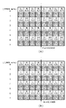
図12は、ウェーブレット変換によって縦4画素横4画素の画像がサブバンドに分割される様子を示したものである。図中のL、Hは変換係数に含まれる周波数成分を表しており、Lは低周波成分、Hは高周波成分を表している。また、カッコ内に示された数字は、元画像における画素の座標を表しており、左側の値が上端から下端に向かう縦方向の座標、右側の値が左端から右端へ向かう横方向の座標を表している。 FIG. 12 shows a state in which an image of 4 pixels in the vertical direction and 4 pixels in the horizontal direction is divided into subbands by the wavelet transform. L and H in the figure represent frequency components included in the conversion coefficient, L represents a low frequency component, and H represents a high frequency component. The numbers shown in parentheses represent the coordinates of the pixels in the original image, the left-hand value is the vertical coordinate from the upper end to the lower end, and the right-hand value is the horizontal coordinate from the left end to the right end. Represents.
2次元DWTでは、はじめに上端から下端に向かう縦の画素ライン毎に左端から右端まで1次元のリフティング演算が行われる。図12(a)は、縦の画素ライン毎に1次元のリフティング演算を行った結果を示している。リフティング演算の後、演算結果をL、Hの成分ごとにまとめる並び替えを行う。係数を並び替えた結果を図12(b)に示す。続いて、左端から右端に向かう横の画素ライン毎に上端から下端まで1次元のリフティング演算を行う。この結果を図12(c)に示す。続いて、縦の画素ライン毎の演算と同様に、演算結果をL、Hの成分ごとにまとめる並び替えを行う。この結果を図12(d)に示す。結果として、ウェーブレット変換で生成された係数は、図12(e)のようにサブバンドにまとめられる。 In the two-dimensional DWT, first, a one-dimensional lifting operation is performed from the left end to the right end for each vertical pixel line from the upper end to the lower end. FIG. 12A shows the result of performing a one-dimensional lifting operation for each vertical pixel line. After the lifting calculation, rearrangement is performed to combine the calculation results for each of the L and H components. The result of rearranging the coefficients is shown in FIG. Subsequently, a one-dimensional lifting operation is performed from the upper end to the lower end for each horizontal pixel line from the left end to the right end. The result is shown in FIG. Subsequently, similar to the calculation for each vertical pixel line, the calculation result is rearranged for each of the L and H components. The result is shown in FIG. As a result, the coefficients generated by the wavelet transform are grouped into subbands as shown in FIG.
図13は、縦4画素横4画素の画像にウェーブレット変換を施して生成されたサブバンドの係数が、元の画像においてどこに位置しているかを示している。図13(a)は上端から下端に向かう縦の画素ライン毎の1次元のDWTにより生成された係数の分布を元の画素の位置関係で示しており、図13(b)は2次元のDWTにより生成された係数の分布を元の画素の位置関係で示している。図13より、画素ラインのアドレスが奇数であるか偶数であるかによって、ウェーブレット変換で生成される係数の周波数成分が異なることがわかる。 FIG. 13 shows where the subband coefficients generated by performing wavelet transform on an image of four vertical pixels and four horizontal pixels are located in the original image. FIG. 13A shows the distribution of the coefficients generated by the one-dimensional DWT for each vertical pixel line from the upper end to the lower end in the positional relationship of the original pixels, and FIG. 13B shows the two-dimensional DWT. The distribution of the coefficients generated by the above is shown by the positional relationship of the original pixels. FIG. 13 shows that the frequency component of the coefficient generated by the wavelet transform differs depending on whether the pixel line address is an odd number or an even number.
上述したように、JPEG2000でウェーブレット変換はTile毎に適用されるので、ここでTileにウェーブレット変換が施されたときの係数の分布について説明する。図14は、縦4画素横8画素の画像を縦横各4画素の2つのTileに分割した場合において、ウェーブレット変換により生成された係数の分布を、元の画素の位置関係で示したものである。図14(a)は、2次元のDWTにより生成された係数の分布を示したものである。また、図14(b)は、図14(a)に示す係数のうち、Tile分割境界の方向と同じ縦方向の周波数成分の分布のみを示したものである。図14(b)より、Tile分割を行うと、Tile分割境界の方向と同じ縦方向の周波数成分に関して、分割境界面に同じ周波数成分の係数が並ぶことがわかる。 As described above, since wavelet transform is applied to each tile in JPEG 2000, the distribution of coefficients when the wavelet transform is performed on the tile will be described here. FIG. 14 shows the distribution of coefficients generated by wavelet transform in terms of the original pixel positional relationship when an image of 4 pixels in the vertical direction and 8 pixels in the horizontal direction is divided into two tiles of 4 pixels in the vertical and horizontal directions. . FIG. 14A shows a distribution of coefficients generated by a two-dimensional DWT. FIG. 14B shows only the distribution of frequency components in the same vertical direction as the direction of the Tile division boundary among the coefficients shown in FIG. From FIG. 14B, it can be seen that when Tile division is performed, coefficients of the same frequency component are arranged on the division boundary surface with respect to the frequency component in the same vertical direction as the direction of the Tile division boundary.
通常、JPEG2000の非可逆圧縮の量子化では、高周波成分を含む係数は、低周波成分を含む係数より大きな量子化ステップで量子化される。これは、低周波成分の視認性に比べて高周波成分の視認性が劣るという人間の視覚特性を利用して、効率よく符号化するためである。結果として、高周波成分を含む係数の量子化誤差は大きくなり、低周波成分を含む係数より劣化する。そして、上述したように、2次元DWTの変換係数は画素ラインのアドレスに応じて高周波成分と低周波成分が並んだ構成を有するため、画素ラインのアドレスに応じて劣化の大きな画素と小さな画素が並ぶことになる。 Normally, in the lossy compression quantization of JPEG 2000, a coefficient including a high frequency component is quantized in a larger quantization step than a coefficient including a low frequency component. This is to efficiently encode using the human visual characteristic that the visibility of the high frequency component is inferior to the visibility of the low frequency component. As a result, the quantization error of the coefficient including the high frequency component becomes larger and deteriorates than the coefficient including the low frequency component. As described above, since the conversion coefficient of the two-dimensional DWT has a configuration in which a high frequency component and a low frequency component are arranged in accordance with the address of the pixel line, a pixel having a large deterioration and a small pixel in accordance with the address of the pixel line. Will be lined up.
また、図12を用いて説明したように、JPEG2000のリフティング演算では画像の端部で画素列を折り返して、仮想の画素列を補う。そのため、不可逆変換を行うと、逆ウェーブレット変換時(復号時)に、仮想の画素列に係る画質劣化が、実際の画素列の生成に影響を与えて、実際の画素列の画質が劣化してしまう。 As described with reference to FIG. 12, in the JPEG2000 lifting calculation, the pixel column is folded at the end of the image to compensate for the virtual pixel column. For this reason, when irreversible conversion is performed, image quality degradation related to the virtual pixel column affects the generation of the actual pixel column during inverse wavelet transform (decoding), and the image quality of the actual pixel column deteriorates. End up.
ここで、仮想の画素列を補間することに伴う画質劣化は、仮想の画素列の影響を最も受ける最端部の画素において最も著しくなる。リフティング演算では補間の必要な画素をその周辺の画素を用いて補間するので、低周波成分の保存性に優れている反面、高周波成分の保存性には優れていない。このため、仮想の画素列を補間したことによる画質劣化は、画像の端部に低周波成分を含む変換係数が生成される場合は軽微であるが、高周波成分を含む変換係数が生成される場合には、復号された画像の端部に著しい画質劣化が生じる可能性がある。 Here, the image quality degradation accompanying the interpolation of the virtual pixel column is most significant in the endmost pixel most affected by the virtual pixel column. In the lifting calculation, pixels that need to be interpolated are interpolated using the peripheral pixels, so that the low-frequency component storage is excellent, but the high-frequency component storage is not excellent. For this reason, image quality degradation due to interpolation of a virtual pixel row is slight when a conversion coefficient including a low frequency component is generated at the edge of the image, but when a conversion coefficient including a high frequency component is generated. May cause significant image quality degradation at the end of the decoded image.
また、図14を用いて説明したように、JPEG2000の非可逆圧縮を行う場合、Tileの境界部分に、境界と同一方向に関して同一の周波数成分を含む係数が並び、特にTile境界の一方に高周波成分を含む係数が一列に並ぶ場合がある。 In addition, as described with reference to FIG. 14, when JPEG2000 irreversible compression is performed, coefficients including the same frequency component in the same direction as the boundary are arranged at the boundary of the tile, and in particular, a high-frequency component is located at one of the tile boundaries. In some cases, the coefficients including are arranged in a line.
この場合、Tile分割境界面に、画素補間に起因する画質劣化の著しい画素が並ぶことになり、結果としてTile分割境界面に不連続面が視認されやすくなってしまう。 In this case, pixels with significant image quality degradation due to pixel interpolation are arranged on the Tile division boundary surface, and as a result, a discontinuous surface is likely to be visually recognized on the Tile division boundary surface.
本発明は、上記問題点を鑑みてなされたものであり、ウェーブレット変換において、Tile境界面に異なる周波数成分を含む係数を並ばせることで、画質劣化の視認性を軽減することを主な目的とする。 The present invention has been made in view of the above problems, and it is a main object of the present invention to reduce visibility of image quality degradation by arranging coefficients including different frequency components on the Tile boundary surface in wavelet transform. To do.
上述の目的は、2次元画像データを所定の画素数から成る画素エリアに分割し、画素エリアごとにウェーブレット変換を行う画像処理装置であって、画素エリアを構成する縦方向の画素ライン又は横方向の画素ライン単位で1次元ウェーブレット変換を行う1次元ウェーブレット変換処理手段を有し、1次元ウェーブレット変換処理手段が、高域周波数成分と低域周波数成分とが交互に出現するように画素ラインを1次元ウェーブレット変換するとともに、隣り合う画素ラインにおいては、高周波成分と低周波成分との出現順序を逆転させて変換を行い、画素エリアの分割境界の方向と同じ方向の周波数成分について、分割境界の面に異なる周波数成分の係数が交互に並ぶようにすることを特徴とする画像処理装置によって達成される。 The above objects, the two-dimensional image data is divided into a pixel area having a predetermined number of pixels, an image processing apparatus for performing a wavelet transform for each pixel area, the vertical direction of the pixel line or the lateral direction in the pixel area has a one-dimensional wavelet transform processing means in the pixel line unit performs one-dimensional wavelet transform, the one-dimensional wavelet transform process unit, the pixel lines as the high frequency components and low frequency components appear alternately 1 as well as the dimension wavelet transform, in adjacent pixels line, reverses the order of appearance of the high frequency and low frequency components have rows the conversion, for the same direction of the frequency component and the direction of the division boundary of the pixel area, the division boundary This is achieved by an image processing apparatus characterized in that coefficients of different frequency components are alternately arranged on the surface.
また、上述の目的は、1つのインタレース画像を構成する2つのフィールド画像に独立してウェーブレット変換を行う画像処理装置であって、フィールド画像データを構成する縦方向の画素ライン又は横方向の画素ライン単位で1次元ウェーブレット変換を行う1次元ウェーブレット変換処理手段と、フィールド画像データの一方に対し、各画素の横方向のアドレスに奇数のオフセットを付加するオフセット付加手段とを有し、1次元ウェーブレット変換処理手段が、画素ラインに含まれる画素の横方向のアドレスが奇数である画素に対しては高域周波数成分又は低域周波数成分の一方が出現するように、偶数である画素に対しては高域周波数成分又は低域周波数成分の他方が出現するように画素ラインを変換し、2つのフィールド画像から1つのインタレース画像を構成した際にインタレース画像における縦方向の1次元周波数成分に異なる周波数成分が交互に並ぶようにすることを特徴とする画像処理装置によっても達成される。 The above-described object is an image processing device that performs wavelet transform independently on two field images constituting one interlaced image, and is a vertical pixel line or horizontal pixel constituting field image data. 1-dimensional wavelet transform processing means for performing 1-dimensional wavelet transform in units of lines, and offset addition means for adding an odd-numbered offset to the horizontal address of each pixel for one of the field image data. For pixels that are even numbers, such that one of the high-frequency components or the low-frequency components appears for pixels whose horizontal addresses of the pixels included in the pixel line are odd. It converts the pixel line as the other high frequency components or low frequency components appear, from the two field images One of the different frequency components in a one-dimensional frequency component in the vertical direction in the interlaced image when constituting an interlaced image is also achieved by an image processing apparatus, characterized in that the alternately arranged.
また、上述の目的は、2次元画像データを所定の画素数から成る画素エリアに分割し、画素エリアごとにウェーブレット変換を行う画像処理方法であって、画素エリアを構成する縦方向の画素ライン又は横方向の画素ライン単位で1次元ウェーブレット変換を行う1次元ウェーブレット変換処理ステップを有し、1次元ウェーブレット変換処理ステップが、高域周波数成分と低域周波数成分とが交互に出現するように画素ラインを1次元ウェーブレット変換するとともに、隣り合う画素ラインにおいては、高周波成分と低周波成分との出現順序を逆転させて変換を行い、画素エリアの分割境界の方向と同じ方向の周波数成分について、分割境界の面に異なる周波数成分の係数が交互に並ぶようにすることを特徴とする画像処理方法によっても達成される。 The object described above is a two-dimensional image data is divided into a pixel area having a predetermined number of pixels, an image processing method for performing a wavelet transform for each pixel area, the vertical direction of the pixel lines in the pixel area or It has a one-dimensional wavelet transform processing step that performs one-dimensional wavelet transform in units of horizontal pixel lines, and the one-dimensional wavelet transform processing step has pixel lines so that high-frequency components and low-frequency components appear alternately. the addition to one-dimensional wavelet transform in the adjacent pixel line is reversed order of appearance of the high frequency and low frequency components have rows the conversion, the frequency components in the same direction as the direction of the division boundary of the pixel area, divided by the image processing method characterized in that coefficients of different frequency components in the plane of the boundary are alternately arranged It is made.
また、上述の目的は、1つのインタレース画像を構成する2つのフィールド画像に独立してウェーブレット変換を行う画像処理方法であって、フィールド画像データを構成する縦方向の画素ライン又は横方向の画素ライン単位で1次元ウェーブレット変換を行う1次元ウェーブレット変換処理ステップと、フィールド画像データの一方に対し、各画素の横方向のアドレスに奇数のオフセットを付加するオフセット付加ステップとを有し、1次元ウェーブレット変換処理ステップが、画素ラインに含まれる画素の横方向のアドレスが奇数である画素に対しては高域周波数成分又は低域周波数成分の一方が出現するように、偶数である画素に対しては高域周波数成分又は低域周波数成分の他方が出現するように画素ラインを変換し、2つのフィールド画像から1つのインタレース画像を構成した際にインタレース画像における縦方向の1次元周波数成分に異なる周波数成分が交互に並ぶようにすることを特徴とする画像処理方法によっても達成される。 Further, the above-described object is an image processing method for performing wavelet transform independently on two field images constituting one interlaced image, in which vertical pixel lines or horizontal pixels constituting field image data are provided. A one-dimensional wavelet transform processing step for performing one-dimensional wavelet transform in units of lines, and an offset addition step for adding an odd offset to the horizontal address of each pixel with respect to one of the field image data. For pixels that are even, the transformation step is such that one of the high frequency components or low frequency components appears for pixels whose horizontal addresses of pixels included in the pixel line are odd. It converts the pixel line as the other high frequency components or low frequency components appear, the two fees Different frequency components in a one-dimensional frequency component in the vertical direction is also achieved by an image processing method characterized by alternately arranged at the time of constructing a single interlaced image from de image in interlaced image.
また、上述の目的は、本発明の方法をコンピュータに実現させるプログラムや、当該プログラムを格納したコンピュータ装置読み取り可能な記録媒体によっても達成される。 The above-described object can also be achieved by a program that causes a computer to implement the method of the present invention, or a computer-readable recording medium that stores the program.
本発明によれば、画像を複数のTileに分割してウェーブレット変換する際に、同じ周波数成分を含む係数が一列に並ばないようにすることで、Tile分割したことによるTile端部の不連続面の視認性を低下させることができる。 According to the present invention, when the image is divided into a plurality of tiles and subjected to wavelet transform, the discontinuous surface at the end of the tile due to the tile division is performed by preventing the coefficients including the same frequency component from being arranged in a line. Visibility can be reduced.
以下、添付図面を参照して本発明をその好適な実施形態に基づき詳細に説明する。
●<第1の実施形態>
はじめに、本発明の第1の実施形態に係る画像処理装置について説明する。
本発明の第1の実施形態に係る画像処理装置は、画像データを入力して、その画像データに、所定の分解レベルまで、上端から下端へ向かう縦の画素ラインおよび左端から右端へ向かう横の画素ライン毎に1次元のリフティング演算を繰り返し行うことで2次元の離散ウェーブレット変換を実現し、算出されたサブバンド係数を出力する。
Hereinafter, the present invention will be described in detail based on preferred embodiments with reference to the accompanying drawings.
● <First embodiment>
First, an image processing apparatus according to the first embodiment of the present invention will be described.
The image processing apparatus according to the first embodiment of the present invention inputs image data, and to the image data, a vertical pixel line from the upper end to the lower end and a horizontal line from the left end to the right end up to a predetermined decomposition level. A two-dimensional discrete wavelet transform is realized by repeatedly performing a one-dimensional lifting operation for each pixel line, and the calculated subband coefficients are output.
図1を用いて装置の大まかな構成を説明すると、本実施形態に係る画像処理装置は、1次元の画素ラインの座標により演算切替器103の出力先を切り替えて、バッファメモリ102から出力された1次元の画素列を、画素補間器A104〜1次元リフティング演算器A106という第1の系統、あるいは画素補間器B105〜1次元リフティング演算器B107という第2の系統で処理することで、画素列に1次元のウェーブレット変換を施し、サブバンド係数を生成する。そして、所定の分解レベルに達するまで、横方向および縦方向において共に低周波成分を含むLL成分を含むサブバンド(LLサブバンド)の係数に2次元の離散ウェーブレット変換を繰り返し行う。
The rough configuration of the apparatus will be described with reference to FIG. 1. The image processing apparatus according to the present embodiment switches the output destination of the
ここで、本発明の第1の実施形態に係る画像処理装置が行う、画素補間器A104〜1次元リフティング演算器A106の第1の系統と、画素補間器B105〜1次元リフティング演算器B107の第2の系統の処理内容について説明する。 Here, the first system of the pixel interpolator A104 to the one-dimensional lifting arithmetic unit A106 and the first unit of the pixel interpolator B105 to the one-dimensional lifting arithmetic unit B107 performed by the image processing apparatus according to the first embodiment of the present invention. The processing contents of the second system will be described.
本実施形態に係る画像処理装置は、Tileに分割された画像(Tile画像)をリフティング演算するとき、縦方向あるいは横方向の画素の座標が偶数であるか奇数であるかにより、リフティング演算の順序を変更する。すなわち、上端から下端へ向かう縦の画素ライン毎に演算を行う場合は、その画素の横方向の座標(ラインの座標)に従って、また、左端から右端までの横の画素ライン毎に演算を行う場合は、その画素の縦方向の座標に従って、リフティング演算の順序を変更する。 When the image processing apparatus according to the present embodiment performs a lifting operation on an image (Tile image) divided into tiles, the order of the lifting operation depends on whether the vertical or horizontal pixel coordinates are even or odd. To change. In other words, when performing calculations for each vertical pixel line from the upper end to the lower end, according to the horizontal coordinates (line coordinates) of the pixel and for each horizontal pixel line from the left end to the right end Changes the order of lifting operations according to the vertical coordinates of the pixel.
このため、画素ラインの座標が偶数であるときのリフティング演算および演算に応じた画素補間処理と、画素ラインの座標が奇数であるときの同処理との2種類の処理を行う。すなわち、画像処理装置は、画素ラインの座標ごとに演算切替器103の出力先を切り替えながら、画素ラインの座標が偶数であるときは、演算切替器103を通じて第1の系統(画素補間器A104〜1次元リフティング演算器A106)を用い、画素ラインの座標が奇数であるときは、同様にして第2の系統(画素補間器B105〜1次元リフティング演算器B107)を用いる。
For this reason, two types of processing are performed: lifting computation when the pixel line coordinates are even, and pixel interpolation processing according to the computation, and the same processing when the pixel line coordinates are odd. That is, the image processing apparatus switches the output destination of the
はじめに、第1の系統(画素補間器A104〜1次元リフティング演算器A106)での処理について説明する。画素補間器A104は、画素列の始点の座標および終点の座標が奇数であるか偶数であるかに応じて、図11を用いて説明したように、所定の個数の画素を画素列の端に補間する。本実施形態で画素補間器A104が補間する画素の個数は、座標が偶数の場合は4画素、奇数の場合は3画素である。 First, processing in the first system (pixel interpolator A104 to one-dimensional lifting arithmetic unit A106) will be described. As described with reference to FIG. 11, the pixel interpolator A104 sets a predetermined number of pixels at the end of the pixel column depending on whether the coordinates of the start point and the end point of the pixel column are odd or even. Interpolate. In this embodiment, the number of pixels interpolated by the pixel interpolator A104 is 4 pixels when the coordinates are even, and 3 pixels when the coordinates are odd.
画素を補間された入力画素列は、1次元リフティング演算器A106にて、1次元のリフティング演算が施される。ここでのリフティング変換の漸化式は次の通りである。 A one-dimensional lifting operation is performed on the input pixel row in which the pixels are interpolated by a one-dimensional lifting operation unit A106. The recurrence formula of the lifting conversion here is as follows.
ただし、
α=−1.586 134 342 059 924
β=−0.052 980 118 572 961
γ= 0.882 911 075 530 934
δ= 0.443 506 852 043 971
K= 1.230 174 104 914 001
nは整数
…(式2)
However,
α = −1.586 134 342 059 924
β = −0.052 980 118 572 961
γ = 0.882 911 075 530 934
δ = 0.443 506 852 043 971
K = 1.230 174 104 914 001
n is an integer
... (Formula 2)
次に、第2の系統(画素補間器B105〜1次元リフティング演算器B107)での処理について説明する。画素補間器B105は、画素列の始点の座標および終点の座標が奇数であるか偶数であるかに応じて、所定の個数の画素を画素列の端に補間する。画素補間器B105において、補間する画素の個数は、端に位置する画素の座標が偶数の場合は3画素、奇数の場合は4画素である。 Next, processing in the second system (pixel interpolator B105 to 1-dimensional lifting arithmetic unit B107) will be described. The pixel interpolator B105 interpolates a predetermined number of pixels at the end of the pixel column depending on whether the coordinates of the start point and end point of the pixel column are odd or even. In the pixel interpolator B105, the number of pixels to be interpolated is 3 pixels when the coordinates of the pixels located at the ends are even, and 4 pixels when the coordinates are odd.
画素を補間された入力画素列は、1次元リフティング演算器B107にて、1次元のリフティング変換が施される。ここでのリフティング変換の漸化式は次の通りである。 The one-dimensional lifting arithmetic unit B107 performs one-dimensional lifting conversion on the input pixel string in which the pixels are interpolated. The recurrence formula of the lifting conversion here is as follows.
(式3)に示す漸化式は、(式2)に示す漸化式について、1次元の入力画素列における画素の座標が奇数のときの演算処理と偶数のときの演算処理とを入れ替えたものである。従って、(式3)のリフティング演算の結果、画素の座標が偶数(Y(2n))の場合は高周波成分、画素の座標が奇数(Y(2n+1))の場合は低周波成分が表れる。すなわち、(式3)におけるstep 2,4,6の演算はハイパスフィルタ処理、step 1,3,5の演算はローパスフィルタ処理と見ることができ、これは(式2)におけるローパスフィルタ処理とハイパスフィルタ処理を入れ替えたものと見ることができる。
The recurrence formula shown in (Formula 3) is the same as the recurrence formula shown in (Formula 2), but replaces the arithmetic processing when the pixel coordinates in the one-dimensional input pixel column are odd and the arithmetic processing when the pixel coordinates are even. Is. Therefore, as a result of the lifting calculation of (Equation 3), a high frequency component appears when the pixel coordinates are even (Y (2n)), and a low frequency component appears when the pixel coordinates are odd (Y (2n + 1)). That is, the operations of
本発明の第1の実施形態に係る画像処理装置に入力された画像は、まず上端から下端へ向かう縦の画素ライン毎に左端から右端までの1次元のリフティング演算が施される。縦の画素ライン毎のリフティング演算は、左端から右端へ向かう横方向の座標が偶数の画素ラインには(式2)を、奇数の画素ラインには(式3)を用いる。この演算結果を図2(a)に示す。縦の画素ライン毎にリフティング演算を行った後、ウェーブレット変換では、演算結果をL、Hの成分ごとに係数をまとめるために、係数の並び替えを行う。並び替えの結果を図2(b)に示す。 The image input to the image processing apparatus according to the first embodiment of the present invention is first subjected to a one-dimensional lifting operation from the left end to the right end for each vertical pixel line from the upper end to the lower end. In the lifting calculation for each vertical pixel line, (Equation 2) is used for pixel lines with an even horizontal coordinate from the left end to the right end, and (Equation 3) is used for odd pixel lines. The calculation result is shown in FIG. After performing the lifting operation for each vertical pixel line, in the wavelet transform, the coefficients are rearranged in order to compile the coefficients for the L and H components. The result of rearrangement is shown in FIG.
本発明の第1の実施形態に係る画像処理装置は、縦の画素ライン毎のリフティング演算に続けて、横の画素ライン毎に上端から下端まで1次元のリフティング演算を行う。横の画素ライン毎のリフティング演算についても、上端から下端に向かう縦方向の座標が偶数の画素ラインには(式2)を、奇数の画素ラインには(式3)を用いる。この演算結果を図2(c)に示す。横の画素ライン毎にリフティング演算を行った後、ウェーブレット変換では、演算結果をL、Hの成分ごとに係数をまとめるために、係数の並び替えを行う。この結果を図2(d)に示す。 The image processing apparatus according to the first embodiment of the present invention performs a one-dimensional lifting calculation from the upper end to the lower end for each horizontal pixel line following the lifting calculation for each vertical pixel line. Also for the lifting calculation for each horizontal pixel line, (Equation 2) is used for pixel lines with an even vertical coordinate from the upper end to the lower end, and (Equation 3) is used for odd pixel lines. The calculation result is shown in FIG. After performing the lifting operation for each horizontal pixel line, in the wavelet transform, the coefficients are rearranged in order to collect the coefficients for the L and H components. The result is shown in FIG.
図3は、縦4画素横4画素の画像に第1の実施形態に係るウェーブレット変換を施して生成されたサブバンドの係数が、元の画像においてどこに位置しているかを示している。図3(a)は上端から下端に向かう縦の画素ライン毎の1次元のウェーブレット変換により生成された係数の分布を元の位置関係で示しており、図3(b)は第1の実施形態に係る2次元のウェーブレット変換により生成された係数の分布を元の画素の位置関係で示している。 FIG. 3 shows where the subband coefficients generated by applying the wavelet transform according to the first embodiment to an image of 4 pixels vertically and 4 pixels horizontally are located in the original image. FIG. 3A shows the distribution of coefficients generated by one-dimensional wavelet transform for each vertical pixel line from the upper end to the lower end in the original positional relationship, and FIG. 3B shows the first embodiment. 2 shows the distribution of coefficients generated by the two-dimensional wavelet transform according to the positional relationship of the original pixels.
図13との比較から明らかなように、本実施形態の画像処理装置による処理結果は、縦方向あるいは横方向の1次元の周波数成分に関して、ウェーブレット変換で生成された係数の周波数成分は、隣接する係数の周波数成分と異なる成分となっていることがわかる。 As is clear from the comparison with FIG. 13, the processing result by the image processing apparatus of this embodiment shows that the frequency component of the coefficient generated by the wavelet transform is adjacent to the one-dimensional frequency component in the vertical direction or the horizontal direction. It turns out that it is a component different from the frequency component of a coefficient.
次に、本実施形態に係る画像処理装置の構成の詳細について、図1を用いて説明する。
バッファメモリ102は、CPU101からの画像データ入力命令に基づいて、ウェーブレット変換を施す画像データを入力する。バッファメモリ102は、CPU101からのデータ列の出力命令に基づいて、データ列を演算切替器103へ出力する。また、1次元リフティング演算器A106あるいは1次元リフティング演算器B107より出力されたサブバンド係数を一時記憶する。また、バッファメモリ102は、CPU101からの係数出力命令に基づいて、演算を終えた全てのサブバンド係数を出力する。
Next, details of the configuration of the image processing apparatus according to the present embodiment will be described with reference to FIG.
The
演算切替器103は、CPU101からの切替情報に基づいて、入力された1次元のデータ列を画素補間器A104あるいは画素補間器B105へ選択的に出力する。
画素補間器A104は、1次元のデータ列とその始点および終点の座標を入力し、(式2)に基づく1次元のリフティング演算に必要な仮想のデータ列を、始点及び終点の座標が奇数か偶数かに応じてデータ列の両端に各々補間し、1次元リフティング演算器A106へ出力する。画素補間器B105は、(式3)に基づく1次元のリフティング演算に必要な仮想のデータ列を、始点及び終点の座標に応じてデータ列の両端に各々補間し、1次元リフティング演算器B107へ出力する。
The
The pixel interpolator A104 inputs a one-dimensional data string and the coordinates of the start point and the end point of the data, and determines whether the virtual data string necessary for the one-dimensional lifting operation based on (Equation 2) is an odd number of coordinates of the start point and the end point. Depending on whether it is an even number, it is interpolated at both ends of the data string and output to the one-dimensional lifting calculator A106. The pixel interpolator B105 interpolates the virtual data string necessary for the one-dimensional lifting calculation based on (Equation 3) at both ends of the data string in accordance with the coordinates of the start point and the end point, and sends it to the one-dimensional lifting calculator B107. Output.
1次元リフティング演算器A106は、1次元のデータ列を入力し、(式2)に示す漸化式に基づいた1次元のリフティング演算を行い、生成された1次元のサブバンド係数について、低周波成分を含む係数を左側へ、高周波成分を含む係数を右側へ詰めるようにして、サブバンドごとに集まるように並び替えを行い、バッファメモリ102へ出力する。1次元リフティング演算器B107は、(式3)に示す漸化式に基づいて、上記と同様の処理を行う。
The one-dimensional lifting arithmetic unit A106 inputs a one-dimensional data string, performs a one-dimensional lifting operation based on the recurrence formula shown in (Equation 2), and generates a low frequency for the generated one-dimensional subband coefficient. The coefficients including the components are rearranged so that the coefficients including the high-frequency components are concentrated on the left side and the coefficients including the high-frequency component are aligned on the right side, and are output to the
CPU101は、はじめに、入力する画像データの画像サイズ情報と、ウェーブレット変換の分解レベル数の情報をたとえば図示しない不揮発性メモリから、あるいは図示しない入力装置等からの設定により、もしくは図示しない外部回路または外部装置から取得した後、画像データに2次元のウェーブレット変換を施すために、バッファメモリ102、演算切替器103、画素補間器A104、画素補間器B105へ、上述した各種の情報や命令を出力する。
First, the
次に、上記構成の画像処理装置の動作について説明する。
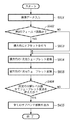
図4は、本発明の第1の実施形態に係る画像処理装置の動作を説明するためのフローチャートである。
はじめにステップS401において、CPU101は、入力する画像データの画像サイズ情報と、ウェーブレット変換の分解レベル数の情報を取得する。画像サイズ情報に基づいて、CPU101はバッファメモリ102へ画像サイズ分のメモリ確保命令と画像データの入力命令を送信する。バッファメモリ102は、CPU101より送信されたメモリ確保命令に基づいて、画像サイズ分の領域を確保し、その後、画像データの入力命令を受信すると、画像データを例えばハードディスク等の外部記憶装置から取得し、確保した領域に一時記憶する。
Next, the operation of the image processing apparatus having the above configuration will be described.
FIG. 4 is a flowchart for explaining the operation of the image processing apparatus according to the first embodiment of the present invention.
First, in step S401, the
次に、ステップS402において、CPU101は、画像の左端から右端まで(横方向)の座標を順次読み込む。座標を読み込む度に、CPU101は演算切替器103へ入力データの出力先を命令する。
Next, in step S402, the
ここで、CPU101が読み込んだ座標が偶数である場合の動作と奇数である場合の動作について説明する。
もし読み込んだ横の画素座標が偶数である場合、CPU101は、バッファメモリ102からの画素列を第1の系統(画素補間器A104)へ出力するように、演算切替器103へ命令する。演算切替器103は、CPU101からの命令に基づいて、入力データが画素補間器A104へ出力するよう、内蔵するスイッチを切り替える。その後、CPU101は、読み込んだ横の画素座標に対応する上端から下端までの縦方向の画素ラインについて、画素列の始点と終点における縦方向の座標を、画素補間器A104へ送信する。その後、CPU101は、その縦方向の画素列を出力するよう、バッファメモリ102へ命令する。バッファメモリ102は、CPU101から送信された命令に基づいて、指定された画素列を演算切替器103へ出力する。
Here, an operation when the coordinates read by the
If the read horizontal pixel coordinate is an even number, the
演算切替器103は、バッファメモリ102より送信された画素列を設定に従って画素補間器A104へ出力する。画素列が入力されると画素補間器A104は、CPU101より送信された画素列の始点および終点の座標に基づいて、例えば図11を用いて説明したように、端に位置する画素の座標が偶数の場合は4画素、奇数の場合は3画素を画素列の両端に補間し、1次元リフティング演算器A106へ出力する。画素列が入力されると1次元リフティング演算器A106は、(式2)の漸化式に基づいた1次元のリフティング演算を画素列全体に行い、演算で生成されたサブバンド係数をサブバンド毎に並び替えて、バッファメモリ102へ出力する。バッファメモリ102は入力されたサブバンド係数を一時記憶する。
The
もし読み込んだ横の画素座標が奇数である場合、CPU101は、バッファメモリ102からの画素列を第2の系統(画素補間器B105)へ出力するように、演算切替器103へ命令する。演算切替器103は、CPU101からの命令に基づいて、入力データが画素補間器B105へ出力するよう、内蔵するスイッチを切り替える。その後、CPU101は、読み込んだ横の画素座標に対応する上端から下端までの縦方向の画素ラインについて、画素列の始点と終点における縦方向の座標を、画素補間器B105へ送信する。その後、CPU101は、その縦方向の画素列を出力するよう、バッファメモリ102へ命令する。バッファメモリ102は、CPU101から送信された命令に基づいて、指定された画素列を演算切替器103へ出力する。
If the read horizontal pixel coordinate is an odd number, the
演算切替器103は、バッファメモリ102より送信された画素列を設定に従って画素補間器B105へ出力する。画素列が入力されると画素補間器B105は、CPU101より送信された画素列の始点および終点の座標に基づいて、端に位置する画素の座標が偶数の場合は3画素、奇数の場合は4画素だけ補間し、1次元リフティング演算器B107へ出力する。画素列が入力されると、1次元リフティング演算器B107は、(式3)の漸化式に基づいた1次元のリフティング演算を画素列全体に行い、演算で生成されたサブバンド係数をサブバンド毎に並び替えて、バッファメモリ102へ出力する。バッファメモリ102は入力されたサブバンド係数を一時記憶する。
The
ステップS402において、以上のような一連の処理を、CPU101が画像の左端から右端まで横方向の画素座標を全てカウントし終えるまで、繰り返し行う。
ここで、縦の画素列毎に左端から右端まで行われる横方向の1次元ウェーブレット変換を処理し終えたときにおける、バッファメモリ102に一時記憶されているサブバンド係数は、1次元リフティング演算器A106あるいは1次元リフティング演算器B107にてサブバンドごとに並び替えが行われるため、図2(b)に示したような、サブバンドごとに係数が集められた状態で一時記憶されている。
In step S402, the series of processes as described above are repeated until the
Here, the subband coefficients temporarily stored in the
次に、ステップS403において、横の画素ラインの座標ごとに上端から下端まで縦方向の画素列について行ったステップS402の処理を、上端から下端まで縦の画素ラインの座標ごとに左端から右端まで横方向の画素列に対して同様に行う。 Next, in step S403, the processing in step S402 performed for the vertical pixel line from the upper end to the lower end for each coordinate of the horizontal pixel line is performed from the left end to the right end for each coordinate of the vertical pixel line from the upper end to the lower end. The same is done for the pixel columns in the direction.
ここで、横の画素ラインの座標ごとに上端から下端まで行われる縦方向の1次元ウェーブレット変換を処理し終えたときにおける、バッファメモリ102に一時記憶されているサブバンド係数は、サブバンドごとに並び替えて記憶されているため、図2(d)に示したような、サブバンドごとに係数が集められた状態で一時記憶されている。
Here, the subband coefficients temporarily stored in the
次に、ステップS404において、CPU101は、ステップS401にて取得した分解レベル数の情報に基づいて、2次元のウェーブレット変換により所定の分解レベルに達したかどうか判断する。もし、所定の分解レベルに達したと判断した場合は、ステップS405へ進み、メモリバッファ102に一時記憶されている全てのサブバンド係数を出力する。もし、所定の分解レベルに達したと判断しなかった場合は、メモリバッファ102に一時記憶されているサブバンド係数のうち、横方向および縦方向において共に低周波成分を含むLLサブバンドについて、再度、ステップS402とステップS403の処理を行う。
Next, in step S404, the
ここで、上述したウェーブレット変換がTileに施されたときの係数の分布について説明する。図5は、縦4画素横8画素の画像を縦横各4画素の2つのTileに分割した場合において、本実施形態に係る画像処理装置によって生成されたウェーブレット変換係数の分布を、元の画素の位置関係で示したものである。図5(a)は、本実施形態に係る画像処理装置による2次元ウェーブレット変換により生成された係数の分布を示したものである。また、図5(b)は、図5(a)に示す係数のうち、Tile分割境界の方向と同じ縦方向の周波数成分の分布のみを示したものである。図5(b)より、Tile分割を行うと、Tile分割境界の方向と同じ縦方向の周波数成分に関して、分割境界面に異なる周波数成分の係数が交互に並ぶことがわかる。 Here, the coefficient distribution when the above-described wavelet transform is applied to Tile will be described. FIG. 5 shows the distribution of wavelet transform coefficients generated by the image processing apparatus according to the present embodiment when the image of 4 pixels vertically and 8 pixels horizontally is divided into two tiles of 4 pixels vertically and horizontally. This is indicated by the positional relationship. FIG. 5A shows the distribution of coefficients generated by the two-dimensional wavelet transform by the image processing apparatus according to the present embodiment. FIG. 5 (b) shows only the distribution of frequency components in the same vertical direction as the direction of the tile division boundary among the coefficients shown in FIG. 5 (a). From FIG. 5B, it can be seen that when Tile division is performed, coefficients of different frequency components are alternately arranged on the division boundary surface with respect to frequency components in the same vertical direction as the direction of the Tile division boundary.
以上の動作を行うことにより、本発明の第1の実施形態に係る画像処理装置は、複数のTileに分割された画像をJPEG2000符号化する際に、縦方向および横方向の画素ラインの座標が偶数であるか奇数であるかにより、リフティング演算の順序を変更することで、同じ周波数成分を含む係数が1列に並ばないようにすることができる。 By performing the above operation, when the image processing apparatus according to the first embodiment of the present invention performs JPEG2000 encoding on an image divided into a plurality of tiles, the coordinates of the pixel lines in the vertical and horizontal directions are changed. By changing the order of the lifting operation depending on whether it is an even number or an odd number, it is possible to prevent the coefficients including the same frequency component from being arranged in a line.
●<第2の実施形態>
以下、本発明の第2の実施形態に係る画像処理装置について説明する。
本実施形態に係る画像処理装置は、インターレース画像を構成する第1のフィールド画像あるいは第2のフィールド画像を入力し、フィールド画像を独立してJPEG2000方式で圧縮する場合に、一方のフィールド画像に対し、JPEG2000方式で定義されるReference gridと呼ばれる座標系に関して横方向のオフセットを付与してJPEG2000方式の圧縮を行うことで、フィールド画像からインターレース画像を構成したときに、インターレース画像における上端から下端へ向かう縦方向の1次元の周波数成分に関して、同じ周波数成分を含む係数が1列に並ばないようにするものである。
● <Second Embodiment>
The image processing apparatus according to the second embodiment of the present invention will be described below.
The image processing apparatus according to the present embodiment inputs a first field image or a second field image constituting an interlaced image, and compresses one field image with respect to one field image when the field image is independently compressed by the JPEG2000 method. By applying a JPEG2000 format compression by applying a horizontal offset to a coordinate system called a reference grid defined in the JPEG2000 format, when an interlaced image is constructed from a field image, the interlaced image moves from the upper end to the lower end. With respect to the one-dimensional frequency component in the vertical direction, coefficients including the same frequency component are prevented from being arranged in a line.
ここで、図6を用いて本実施形態に係る画像処理装置の大まかな構成を説明する。図6において、図1と同じ構成には同じ参照数字を付してある。本実施形態に係る画像処理装置は、バッファメモリ102から出力された1次元の画素列が、CPU601から出力される入力画像の座標情報に基づいて、画素補間器A104〜1次元リフティング演算器A106で処理されることで、画素列に1次元のウェーブレット変換が施され、サブバンド係数が生成される。Reference gridにCPU601がオフセットを付与するフィールド画像が入力画像である場合、オフセットを付与された座標情報がCPU601より画素補間器A104と1次元リフティング演算器A106へ送信される。本実施形態に係る画像処理装置は、所定の分解レベルに達するまで、LL成分を含むサブバンド係数に2次元のウェーブレット変換を繰り返し行う。
Here, a rough configuration of the image processing apparatus according to the present embodiment will be described with reference to FIG. In FIG. 6, the same components as those in FIG. 1 are denoted by the same reference numerals. In the image processing apparatus according to the present embodiment, the one-dimensional pixel row output from the
この処理について、図7に示す縦8画素横4画素のインターレース画像を用いて詳細に説明する。図7は、第2フィールド画像のReference gridに横方向のオフセットを1だけ付与して、画像を2次元のウェーブレット変換し、サブバンドに分割する処理を説明するための模式図である。図7(a)は、入力されるフィールド画像で構成される元画像のインターレース画像である。また、インターレース画像から分割された第1のフィールド画像と第2のフィールド画像を図7(b)に示す。なお、図7中にある“元画像 line No.”とは、インターレース画像における上端から下端に向かう縦のアドレス番号である。また、カッコ内に示された数字は、各フィールド画像におけるオフセット付与後の画素の座標を表しており、左側の値が上端から下端に向かう縦方向の座標、右側の値が左端から右端に向かう横方向の座標を表している。図7(b)に示すように、第2フィールド画像は横方向に+1のオフセットが付与されている。 This process will be described in detail using an interlaced image of 8 pixels vertically and 4 pixels horizontally shown in FIG. FIG. 7 is a schematic diagram for explaining a process of assigning only one lateral offset to the reference grid of the second field image, performing two-dimensional wavelet transform, and dividing the image into subbands. FIG. 7A is an interlaced image of an original image composed of input field images. Moreover, the 1st field image and 2nd field image which were divided | segmented from the interlace image are shown in FIG.7 (b). Note that “original image line No.” in FIG. 7 is a vertical address number from the upper end to the lower end of the interlaced image. The numbers shown in parentheses represent the coordinates of the pixel after offset addition in each field image, the left value is the vertical coordinate from the upper end to the lower end, and the right value is from the left end to the right end. Represents horizontal coordinates. As shown in FIG. 7B, the second field image is given an offset of +1 in the horizontal direction.
図7(b)の上段が図7(a)のインタレース画像(フレーム画像)を構成する第1フィールド画像であり、下段が同じく第2フィールド画像である。画像処理装置に入力された所定のフレーム画像は、各フィールド画像毎にまず上端から下端に向かう縦方向の画素ライン毎に左端から右端まで(式2)を用いた1次元リフティング演算が施される。この演算結果を図7(c)に示す。縦の画素ライン毎にリフティング演算を行った後、ウェーブレット変換では、演算結果をL、Hの成分ごとに係数をまとめるために、係数の並び替えを行う。並び替えの結果を図7(d)に示す。 The upper part of FIG. 7B is a first field image constituting the interlaced image (frame image) of FIG. 7A, and the lower part is a second field image. The predetermined frame image input to the image processing apparatus is subjected to a one-dimensional lifting operation using (Equation 2) from the left end to the right end for each vertical pixel line from the upper end to the lower end for each field image. . The calculation result is shown in FIG. After performing the lifting operation for each vertical pixel line, in the wavelet transform, the coefficients are rearranged in order to compile the coefficients for the L and H components. The result of the rearrangement is shown in FIG.
本実施形態に係る画像処理装置は、縦の画素ライン毎のリフティング演算に続けて、横の画素ライン毎に上端から下端まで(式2)を用いた1次元リフティング演算を行う。この演算結果を図7(e)に示す。ここで、第1のフィールド画像については、reference gridの座標値にオフセットを付与しなかったため、左端から右端に向かう横方向のアドレスは0つまり偶数で始まる。したがって、リフティング演算で生成される第1のフィールド画像のサブバンド係数に関して、係数に含まれる縦方向の1次元の周波数成分は、上端から下端にかけてLを先頭にL、H、L、・・・と並ぶ。これに対して、第2フィールド画像については、横方向にオフセット値1を付与したため、横方向のアドレスは1つまり奇数で始まる。したがって、リフティング演算で生成される第2のフィールド画像のサブバンド係数に関して、係数に含まれる縦方向の1次元周波数成分は、上端から下端にかけてHを先頭にH、L、H、・・・と並ぶ。
The image processing apparatus according to the present embodiment performs a one-dimensional lifting calculation using (Equation 2) from the upper end to the lower end for each horizontal pixel line following the lifting calculation for each vertical pixel line. The calculation result is shown in FIG. Here, for the first field image, since no offset is given to the coordinate value of the reference grid, the horizontal address from the left end to the right end starts with 0, that is, an even number. Therefore, regarding the subband coefficients of the first field image generated by the lifting operation, the vertical one-dimensional frequency component included in the coefficients is L, H, L,. Lined up. On the other hand, for the second field image, since the offset
よって、図7(e)より、同じサイズの画像であっても、Reference gridへオフセットを付与するか付与しないかにより、リフティング演算により生成されるサブバンド係数の出方が異なることがわかる。横の画素ライン毎にリフティング演算を行った後、ウェーブレット変換では、演算結果をL、Hの成分ごとに係数をまとめるために、係数の並び替えを行う。この結果を図7(f)に示す。 Therefore, it can be seen from FIG. 7 (e) that even when the images have the same size, the subband coefficients generated by the lifting operation differ depending on whether the offset is applied to the reference grid. After performing the lifting operation for each horizontal pixel line, in the wavelet transform, the coefficients are rearranged in order to collect the coefficients for the L and H components. The result is shown in FIG.
図8は、図7に示す第1及び第2フィールドの変換係数が、元の縦8画素横4画素のフレーム画像においてどこに位置しているかを示している。図8(a)は上端から下端に向かう縦の画素ライン毎の(横方向の)1次元のウェーブレット変換により生成された係数の分布を元の位置関係で示している。また、図8(b)は同様に2次元のウェーブレット変換により生成された係数の分布を元の画素の位置関係で示している。 FIG. 8 shows where the conversion coefficients of the first and second fields shown in FIG. 7 are located in the original frame image of 8 pixels vertically and 4 pixels horizontally. FIG. 8A shows the distribution of coefficients generated by one-dimensional wavelet transform (in the horizontal direction) for each vertical pixel line from the upper end to the lower end in the original positional relationship. Similarly, FIG. 8B shows the distribution of coefficients generated by the two-dimensional wavelet transform in the positional relationship of the original pixels.
図7(e)に示すように、オフセットが付与されてない第1のフィールド画像では、縦の画素ライン毎に左端から右端にかけてL、H、L、HとLを先頭にとサブバンド係数が並び、オフセットが付与された第2のフィールド画像では、縦の画素ライン毎に左端から右端にかけてH、L、H、LとHを先頭にサブバンド係数が並んでいるので、第1のフィールド画像を偶数ラインに、第2のフィールド画像を奇数ラインに配置した図8(b)のインターレース画像における縦方向の1次元の周波数成分は、LとHが交互に現れる。これらのことから、図8より、上端から下端へ向かう縦方向の1次元の周波数成分に関して、ウェーブレット変換で生成された係数の周波数成分は、隣接する係数の周波数成分と異なる成分となっていることがわかる。 As shown in FIG. 7E, in the first field image to which no offset is given, the subband coefficients are L, H, L, H and L starting from the left end to the right end for each vertical pixel line. In the second field image to which the array and offset are added, since the subband coefficients are arranged with H, L, H, L, and H as the head from the left end to the right end for each vertical pixel line, the first field image L and H appear alternately in the one-dimensional frequency component in the vertical direction in the interlaced image in FIG. 8B in which the second field image is arranged on the odd lines. From these facts, as shown in FIG. 8, regarding the one-dimensional frequency component in the vertical direction from the upper end to the lower end, the frequency component of the coefficient generated by the wavelet transform is different from the frequency component of the adjacent coefficient. I understand.
なお、上述した説明ではReference gridに横方向のオフセットを1だけ付与していたが、これに限らず、オフセットは任意の正の奇数であれば良い。また、第2のフィールド画像ではなく、第1のフィールド画像にオフセットを付与しても良い。また、オフセットの差が奇数となれば、両方のフィールド画像にオフセットを付与しても良い。 In the above description, only one lateral offset is given to the reference grid. However, the present invention is not limited to this, and the offset may be any positive odd number. Further, an offset may be given to the first field image instead of the second field image. If the difference in offset is an odd number, an offset may be given to both field images.
次に、本発明の第2の実施形態に係る画像処理装置の構成の詳細について、図6を用いて説明する。なお、図6において、本発明の第1の実施形態と同等の機能を有する構成部を同一番号で表している。 Next, details of the configuration of the image processing apparatus according to the second embodiment of the present invention will be described with reference to FIG. In FIG. 6, components having functions equivalent to those of the first embodiment of the present invention are denoted by the same numbers.
バッファメモリ102は、CPU601からの画像データ入力命令に基づいて、ウェーブレット変換を施す画像データを入力する。バッファメモリ102は、CPU601からのデータ列の出力命令に基づいて、データ列を画素補間器A104へ出力する。また、1次元リフティング演算器A106より出力されたサブバンド係数を一時記憶する。また、バッファメモリ102は、CPU601からの係数出力命令に基づいて、演算を終えた全てのサブバンド係数を出力する。
The
画素補間器A104および1次元リフティング演算器A106は、第1の実施形態と同様の処理を行い、バッファメモリ102より出力されたデータ列に1次元のウェーブレット変換を施す。
The pixel interpolator A104 and the one-dimensional lifting calculator A106 perform the same processing as in the first embodiment, and perform one-dimensional wavelet transformation on the data string output from the
CPU601は、はじめに、入力する画像データの画像サイズ情報と、ウェーブレット変換の分解レベル数の情報と、入力画像が第1のフィールド画像であるか第2のフィールド画像であるかを判別するフィールド区分情報を入力する。CPU601は、画像データに2次元のウェーブレット変換を施すために、バッファメモリ102、演算切替器103、画素補間器A104、画素補間器B105へ、既に上述した各種の情報や命令を各々へ出力する。もし、入力画像のReference gridのオフセットが値を付与されるフィールド画像である場合、CPU601は画像のReference gridにおける横方向の座標に所定のオフセット値を付与する。
First, the
次に、図9に示すフローチャートを用いて本実施形態に係る画像処理装置の動作について説明する。なお、図9において、第1の実施形態と同等の処理を行うステップを同一番号で表している。また、以下の説明においては、これまでの説明と合わせてReference gridの横方向の座標に付与するオフセットは1、オフセットを付与するフィールド画像は第2のフィールド画像のみとしている。 Next, the operation of the image processing apparatus according to the present embodiment will be described using the flowchart shown in FIG. In FIG. 9, steps that perform the same processing as in the first embodiment are denoted by the same numbers. In the following description, the offset to be given to the horizontal coordinate of the reference grid is 1 and the field image to which the offset is given is only the second field image in combination with the above explanation.
はじめにステップS901において、CPU601は、画像データの画像サイズ情報と、ウェーブレット変換の分解レベル数の情報と、入力画像が第1のフィールド画像であるか第2のフィールド画像であるかを判別するフィールド区分情報を取得する。画像サイズ情報に基づいて、CPU601は、バッファメモリ102へ画像サイズ分のメモリ確保命令と画像データの入力命令を送信する。バッファメモリ102は、CPU601より送信されたメモリ確保命令に基づいて、画像サイズ分の領域を確保し、その後、画像データの入力命令を受信すると、画像データを入力する。
First, in step S901, the
次に、ステップS902において、CPU601は、取得したフィールド区分情報が第1のフィールド画像を示すものであるか、第2のフィールド画像を示すものであるかを判断する。もし、フィールド区分情報が第2のフィールド区分画像を示すものであれば、ステップS903へ進む。もし、入力されたフィールド区分情報が第1のフィールド区分画像を示すものであれば、ステップS904へ進む。
ステップS903において、CPU601は、第2のフィールド画像のReference gridの横方向の座標にオフセット値1を付与する。
Next, in step S <b> 902, the
In step S903, the
ステップS904において、CPU601は、画像サイズの左端から右端まで横の画素座標を順次読み込む。また、CPU601は、読み込んだ横の画素座標に対応する上端から下端までの縦方向の画素列について、画素列の始点と終点における縦方向の座標を、画素補間器A104および1次元リフティング演算器A106へ送信する。その後、CPU601は、読み込んだ横の画素座標に対応する縦方向の画素列を出力する命令を、バッファメモリ102へ送信する。
In step S904, the
バッファメモリ102は、CPU601から送信された命令に基づいて、指定された画素列を画素補間器A104へ出力する。画素補間器A104に画素列が入力されると、画素補間器A104は、CPU601より送信された画素列の始点および終点の座標値に基づいて、例えば図11を用いて説明したように、端に位置する画素の座標が偶数の場合は4画素、奇数の場合は3画素を画素列の両端に補間し、1次元リフティング演算器A106へ出力する。画素列が入力されると、1次元リフティング演算器A106は、(式2)の漸化式に基づいた1次元リフティング演算を画素列全体に行い、演算で生成されたサブバンド係数はさらにサブバンド毎に並び替えて、バッファメモリ102へ出力する。バッファメモリ102は入力されたサブバンド係数を一時記憶する。
The
ステップS904において、以上のような一連の処理を、CPU601が画像の左端から右端まで横方向の座標を全てカウントし終えるまで、繰り返し行う。この結果を図7(c)に示す。なお、図7(c)において、上段の図が第1のフィールド画像の場合、下段の図が第2のフィールド画像の場合の様態である。
In step S904, the series of processes as described above are repeated until the
ここで、縦の画素列毎に左端から右端まで行われる横方向の1次元ウェーブレット変換を処理し終えたときにおける、バッファメモリ102に一時記憶されているサブバンド係数の様態を図7(d)に示す。なお、図7(d)において、上段の図が第1のフィールド画像の場合、下段の図が第2のフィールド画像の場合の様態である。サブバンド係数は、1次元リフティング演算器A106にてサブバンドごとに並び替えが行われるため、サブバンド毎に係数が集められた状態で一時記憶されている。
Here, FIG. 7D shows the state of the subband coefficients temporarily stored in the
次に、ステップS905において、横の画素ラインの座標ごとに上端から下端まで縦方向の画素列について行ったステップS904の処理を、縦の画素座標ごとに左端から右端まで横方向の画素列で同様に行う。この結果を図7(e)に示す。なお、図7(e)において、上段の図が第1のフィールド画像の場合、下段の図が第2のフィールド画像の場合の様態である。 Next, in step S905, the processing in step S904 performed for the vertical pixel column from the upper end to the lower end for each horizontal pixel line coordinate is the same for the horizontal pixel column from the left end to the right end for each vertical pixel coordinate. To do. The result is shown in FIG. In FIG. 7E, the upper diagram is a first field image, and the lower diagram is a second field image.
ここで、横の画素列毎に上端から下端まで行われる縦方向の1次元ウェーブレット変換を処理し終えたときにおける、バッファメモリ102に一時記憶されているサブバンド係数を図7(f)に示す。サブバンド係数は、サブバンドごとに並び替えて記憶されるため、サブバンドごとに係数が集められた状態で一時記憶されている。なお、図7(f)において、上段の図が第1のフィールド画像の場合、下段の図が第2のフィールド画像の場合の様態である。
Here, FIG. 7 (f) shows the subband coefficients temporarily stored in the
次に、ステップS404において、第1の実施形態と同様に、CPU601は、ステップS901にて取得した分解レベル数の情報に基づいて、2次元のウェーブレット変換により所定の分解レベルに達したかどうかを判断する。もし、所定の分解レベルに達したと判断した場合は、ステップS405へ進み、メモリバッファ102に一時記憶されている全てのサブバンド係数を出力する。もし、所定の分解レベルに達したと判断しなかった場合は、メモリバッファ102に一時記憶されているサブバンド係数のうち、横方向および縦方向において共に低周波成分を含むLLサブバンドについて、再度、ステップS904とステップS905の処理を行う。
Next, in step S404, as in the first embodiment, the
ここで、本実施形態における画像処理装置が実施するウェーブレット変換がTileに施されたときの係数の分布について、縦8画素横8画素のインターレース画像を用いて説明する。図10は、このインターレース画像を縦8画素横4画素の2つのTileに分割された場合において、本実施形態で実施するウェーブレット変換により生成された係数の分布を、元の画素の位置関係で示したものである。図10(a)は、本実施形態における2次元のウェーブレット変換により生成された係数の分布を示したものである。また、図10(b)は、図10(a)に示す係数のうち、Tile分割境界の方向と同じ縦方向の周波数成分の分布のみを示したものである。図10(b)より、Tile分割を行うと、Tile分割境界の方向と同じ縦方向の周波数成分に関して、分割境界面に異なる周波数成分の係数が交互に並ぶことがわかる。 Here, the distribution of coefficients when the wavelet transform performed by the image processing apparatus according to the present embodiment is applied to Tile will be described using an interlaced image of 8 pixels in the vertical direction and 8 pixels in the horizontal direction. FIG. 10 shows the distribution of coefficients generated by the wavelet transform performed in this embodiment in the positional relationship of the original pixels when this interlaced image is divided into two tiles of 8 pixels in the vertical direction and 4 pixels in the horizontal direction. It is a thing. FIG. 10A shows the distribution of coefficients generated by the two-dimensional wavelet transform in this embodiment. FIG. 10B shows only the distribution of frequency components in the same vertical direction as the direction of the Tile division boundary among the coefficients shown in FIG. From FIG. 10B, it can be seen that when Tile division is performed, coefficients of different frequency components are alternately arranged on the division boundary surface with respect to frequency components in the same vertical direction as the direction of the Tile division boundary.
以上説明したように、本実施形態に係る画像処理装置は、インターレース画像を構成する第1のフィールド画像あるいは第2のフィールド画像を入力してそれぞれを独立してJPEG2000方式の符号化を行う場合、Reference gridに横方向のオフセットの差が正の奇数となるよう、少なくとも一方のフィールド画像にオフセットを付与し、JPEG2000方式の符号化を行うことで、上端から下端へ向かう縦方向の1次元周波数成分について、同じ周波数成分を含む係数が1列に並ばないようにすることができる。 As described above, when the image processing apparatus according to the present embodiment inputs the first field image or the second field image constituting the interlaced image and independently encodes each of them, A one-dimensional frequency component in the vertical direction from the upper end to the lower end by adding an offset to at least one field image so that the difference in offset in the horizontal direction is a positive odd number in the Reference grid and performing JPEG2000 encoding. , It is possible to prevent the coefficients including the same frequency component from being arranged in a line.
<他の実施形態>
上述の実施形態においては、1つの機器から構成される画像処理装置についてのみ説明したが、同等の機能を複数の機器から構成されるシステムによって実現しても良い。
尚、前述した実施形態の機能を実現するソフトウェアのプログラムを、記録媒体から直接、或いは有線/無線通信を用いて当該プログラムを実行可能なコンピュータを有するシステム又は装置に供給し、そのシステム或いは装置のコンピュータが該供給されたプログラムを実行することによって同等の機能が達成される場合も本発明に含む。
<Other embodiments>
In the above-described embodiment, only the image processing apparatus including one device has been described. However, an equivalent function may be realized by a system including a plurality of devices.
A software program that realizes the functions of the above-described embodiments is supplied directly from a recording medium or to a system or apparatus having a computer that can execute the program using wired / wireless communication. The present invention includes a case where an equivalent function is achieved by a computer executing the supplied program.
従って、本発明の機能処理をコンピュータで実現するために、該コンピュータに供給、インストールされるプログラムコード自体も本発明を実現するものである。つまり、本発明の機能処理を実現するためのコンピュータプログラム自体も本発明に含まれる。
その場合、プログラムの機能を有していれば、オブジェクトコード、インタプリタにより実行されるプログラム、OSに供給するスクリプトデータ等、プログラムの形態を問わない。
Accordingly, the program code itself supplied and installed in the computer in order to implement the functional processing of the present invention by the computer also realizes the present invention. That is, the computer program itself for realizing the functional processing of the present invention is also included in the present invention.
In this case, the program may be in any form as long as it has a program function, such as an object code, a program executed by an interpreter, or script data supplied to the OS.
プログラムを供給するための記録媒体としては、例えば、フレキシブルディスク、ハードディスク、磁気テープ等の磁気記録媒体、MO、CD−ROM、CD−R、CD−RW、DVD−ROM、DVD−R、DVD−RW等の光/光磁気記憶媒体、不揮発性の半導体メモリなどがある。 As a recording medium for supplying the program, for example, a magnetic recording medium such as a flexible disk, a hard disk, a magnetic tape, MO, CD-ROM, CD-R, CD-RW, DVD-ROM, DVD-R, DVD- There are optical / magneto-optical storage media such as RW, and non-volatile semiconductor memory.
有線/無線通信を用いたプログラムの供給方法としては、コンピュータネットワーク上のサーバに本発明を形成するコンピュータプログラムそのもの、もしくは圧縮され自動インストール機能を含むファイル等、クライアントコンピュータ上で本発明を形成するコンピュータプログラムとなりうるデータファイル(プログラムデータファイル)を記憶し、接続のあったクライアントコンピュータにプログラムデータファイルをダウンロードする方法などが挙げられる。この場合、プログラムデータファイルを複数のセグメントファイルに分割し、セグメントファイルを異なるサーバに配置することも可能である。
つまり、本発明の機能処理をコンピュータで実現するためのプログラムデータファイルを複数のユーザに対してダウンロードさせるサーバ装置も本発明に含む。
As a program supply method using wired / wireless communication, a computer program forming the present invention on a server on a computer network, or a computer forming the present invention on a client computer such as a compressed file including an automatic installation function A method of storing a data file (program data file) that can be a program and downloading the program data file to a connected client computer can be used. In this case, the program data file can be divided into a plurality of segment files, and the segment files can be arranged on different servers.
That is, the present invention includes a server device that allows a plurality of users to download a program data file for realizing the functional processing of the present invention on a computer.
また、本発明のプログラムを暗号化してCD−ROM等の記憶媒体に格納してユーザに配布し、所定の条件を満たしたユーザに対して暗号化を解く鍵情報を、例えばインターネットを介してホームページからダウンロードさせることによって供給し、その鍵情報を使用することにより暗号化されたプログラムを実行してコンピュータにインストールさせて実現することも可能である。 In addition, the program of the present invention is encrypted, stored in a storage medium such as a CD-ROM, distributed to the user, and key information for decrypting the encryption for a user who satisfies a predetermined condition is provided via a homepage via the Internet, for example. It is also possible to realize the program by downloading it from the computer and executing the encrypted program using the key information and installing it on the computer.
また、コンピュータが、読み出したプログラムを実行することによって、前述した実施形態の機能が実現される他、そのプログラムの指示に基づき、コンピュータ上で稼動しているOSなどが、実際の処理の一部または全部を行ない、その処理によっても前述した実施形態の機能が実現され得る。 In addition to the functions of the above-described embodiments being realized by the computer executing the read program, the OS running on the computer based on the instruction of the program is a part of the actual processing. Alternatively, the functions of the above-described embodiment can be realized by performing all of them and performing the processing.
さらに、記録媒体から読み出されたプログラムが、コンピュータに挿入された機能拡張ボードやコンピュータに接続された機能拡張ユニットに備わるメモリに書き込まれた後、そのプログラムの指示に基づき、その機能拡張ボードや機能拡張ユニットに備わるCPUなどが実際の処理の一部または全部を行ない、その処理によっても前述した実施形態の機能が実現され得る。 Furthermore, after the program read from the recording medium is written in a memory provided in a function expansion board inserted into the computer or a function expansion unit connected to the computer, the function expansion board or The CPU of the function expansion unit performs part or all of the actual processing, and the functions of the above-described embodiments can also be realized by the processing.
Claims (8)
前記画素エリアを構成する縦方向の画素ライン又は横方向の画素ライン単位で1次元ウェーブレット変換を行う1次元ウェーブレット変換処理手段を有し、
前記1次元ウェーブレット変換処理手段が、
高域周波数成分と低域周波数成分とが交互に出現するように前記画素ラインを1次元ウェーブレット変換するとともに、
隣り合う画素ラインにおいては、前記高周波成分と前記低周波成分との出現順序を逆転させて変換を行い、前記画素エリアの分割境界の方向と同じ方向の周波数成分について、前記分割境界の面に異なる周波数成分の係数が交互に並ぶようにすることを特徴とする画像処理装置。 An image processing apparatus that divides two-dimensional image data into pixel areas having a predetermined number of pixels and performs wavelet transform for each pixel area ,
Has a one-dimensional wavelet transform processing means for performing one-dimensional wavelet transform on a pixel line basis in the vertical direction of the pixel line or the lateral direction that constitute the pixel area,
The one-dimensional wavelet transform processing means is
The pixel line is subjected to a one-dimensional wavelet transform so that a high frequency component and a low frequency component appear alternately,
In the adjacent pixel lines, wherein the high-frequency component reverses the order of appearance of the low-frequency components have rows the conversion, for the same direction of the frequency component and the direction of the division boundary of the pixel area, the surface of the division boundary An image processing apparatus , wherein coefficients of different frequency components are alternately arranged .
前記フィールド画像データを構成する縦方向の画素ライン又は横方向の画素ライン単位で1次元ウェーブレット変換を行う1次元ウェーブレット変換処理手段と、
前記フィールド画像データの一方に対し、各画素の横方向のアドレスに奇数のオフセットを付加するオフセット付加手段とを有し、
前記1次元ウェーブレット変換処理手段が、
前記画素ラインに含まれる画素の横方向のアドレスが奇数である画素に対しては高域周波数成分又は低域周波数成分の一方が出現するように、偶数である画素に対しては高域周波数成分又は低域周波数成分の他方が出現するように前記画素ラインを変換し、前記2つのフィールド画像から1つのインタレース画像を構成した際に前記インタレース画像における縦方向の1次元周波数成分に異なる周波数成分が交互に並ぶようにすることを特徴とする画像処理装置。 An image processing apparatus that performs wavelet transform independently on two field images constituting one interlaced image,
One-dimensional wavelet transform processing means for performing one-dimensional wavelet transform in units of vertical pixel lines or horizontal pixel lines constituting the field image data;
Offset adding means for adding an odd offset to the horizontal address of each pixel with respect to one of the field image data;
The one-dimensional wavelet transform processing means is
The high frequency component is applied to a pixel that is an even number, such that one of a high frequency component or a low frequency component appears for a pixel that has an odd horizontal address in the pixel line. Alternatively, when the pixel line is transformed so that the other of the low frequency components appears and one interlaced image is constructed from the two field images, the frequency differs in the one-dimensional frequency component in the vertical direction in the interlaced image. An image processing apparatus, wherein components are arranged alternately .
前記画素エリアを構成する縦方向の画素ライン又は横方向の画素ライン単位で1次元ウェーブレット変換を行う1次元ウェーブレット変換処理ステップを有し、
前記1次元ウェーブレット変換処理ステップが、
高域周波数成分と低域周波数成分とが交互に出現するように前記画素ラインを1次元ウェーブレット変換するとともに、
隣り合う画素ラインにおいては、前記高周波成分と前記低周波成分との出現順序を逆転させて変換を行い、前記画素エリアの分割境界の方向と同じ方向の周波数成分について、前記分割境界の面に異なる周波数成分の係数が交互に並ぶようにすることを特徴とする画像処理方法。 An image processing method for dividing two-dimensional image data into pixel areas having a predetermined number of pixels and performing wavelet transform for each pixel area ,
Has a one-dimensional wavelet transform processing step of performing one-dimensional wavelet transform on a pixel line basis in the vertical direction of the pixel line or the lateral direction that constitute the pixel area,
The one-dimensional wavelet transform processing step includes:
The pixel line is subjected to a one-dimensional wavelet transform so that a high frequency component and a low frequency component appear alternately,
In the adjacent pixel lines, wherein the high-frequency component reverses the order of appearance of the low-frequency components have rows the conversion, for the same direction of the frequency component and the direction of the division boundary of the pixel area, the surface of the division boundary An image processing method, wherein coefficients of different frequency components are alternately arranged .
前記フィールド画像データを構成する縦方向の画素ライン又は横方向の画素ライン単位で1次元ウェーブレット変換を行う1次元ウェーブレット変換処理ステップと、
前記フィールド画像データの一方に対し、各画素の横方向のアドレスに奇数のオフセットを付加するオフセット付加ステップとを有し、
前記1次元ウェーブレット変換処理ステップが、
前記画素ラインに含まれる画素の横方向のアドレスが奇数である画素に対しては高域周波数成分又は低域周波数成分の一方が出現するように、偶数である画素に対しては高域周波数成分又は低域周波数成分の他方が出現するように前記画素ラインを変換し、前記2つのフィールド画像から1つのインタレース画像を構成した際に前記インタレース画像における縦方向の1次元周波数成分に異なる周波数成分が交互に並ぶようにすることを特徴とする画像処理方法。 An image processing method for performing wavelet transform independently on two field images constituting one interlaced image,
A 1-dimensional wavelet transform processing step of performing one-dimensional wavelet transform on a pixel line basis in the vertical direction of the pixel line or lateral constituting the field image data,
An offset addition step of adding an odd offset to the horizontal address of each pixel with respect to one of the field image data;
The one-dimensional wavelet transform processing step includes:
The high frequency component is applied to a pixel that is an even number, such that one of a high frequency component or a low frequency component appears for a pixel that has an odd horizontal address in the pixel line. Alternatively, when the pixel line is transformed so that the other of the low frequency components appears and one interlaced image is constructed from the two field images, the frequency differs in the one-dimensional frequency component in the vertical direction in the interlaced image. An image processing method, wherein components are arranged alternately .
Priority Applications (1)
| Application Number | Priority Date | Filing Date | Title |
|---|---|---|---|
| JP2003374819A JP4194472B2 (en) | 2003-11-04 | 2003-11-04 | Image processing method and apparatus |
Applications Claiming Priority (1)
| Application Number | Priority Date | Filing Date | Title |
|---|---|---|---|
| JP2003374819A JP4194472B2 (en) | 2003-11-04 | 2003-11-04 | Image processing method and apparatus |
Publications (3)
| Publication Number | Publication Date |
|---|---|
| JP2005142673A JP2005142673A (en) | 2005-06-02 |
| JP2005142673A5 JP2005142673A5 (en) | 2006-12-21 |
| JP4194472B2 true JP4194472B2 (en) | 2008-12-10 |
Family
ID=34686417
Family Applications (1)
| Application Number | Title | Priority Date | Filing Date |
|---|---|---|---|
| JP2003374819A Expired - Fee Related JP4194472B2 (en) | 2003-11-04 | 2003-11-04 | Image processing method and apparatus |
Country Status (1)
| Country | Link |
|---|---|
| JP (1) | JP4194472B2 (en) |
Families Citing this family (4)
| Publication number | Priority date | Publication date | Assignee | Title |
|---|---|---|---|---|
| WO2008143158A1 (en) | 2007-05-17 | 2008-11-27 | Sony Corporation | Information processing device and method |
| US8503809B2 (en) | 2007-05-17 | 2013-08-06 | Sony Corporation | Information processing apparatus and method to entropy code upon processing of predetermined number of precincts |
| JP4821835B2 (en) * | 2008-05-16 | 2011-11-24 | ソニー株式会社 | Information processing apparatus and method |
| CN101631243B (en) * | 2009-08-07 | 2011-10-26 | 清华大学 | Image encoding/decoding method based on wavelet transformation |
-
2003
- 2003-11-04 JP JP2003374819A patent/JP4194472B2/en not_active Expired - Fee Related
Also Published As
| Publication number | Publication date |
|---|---|
| JP2005142673A (en) | 2005-06-02 |
Similar Documents
| Publication | Publication Date | Title |
|---|---|---|
| US7577308B2 (en) | Image data generation with reduced amount of processing | |
| US7190838B2 (en) | Method and device for processing a coded digital signal | |
| JP4707681B2 (en) | Multi-resolution image data management system and method based on tiled wavelet transform and sparse data coding | |
| US7529417B2 (en) | Apparatus, method and storage medium for image encoding/decoding using shape-based coefficient interpolation | |
| US7302105B2 (en) | Moving image coding apparatus, moving image decoding apparatus, and methods therefor | |
| JP5520122B2 (en) | Data converter | |
| JPH11285006A (en) | Image encoder and image decoder | |
| JP2002176553A (en) | Picture processor, its method, program, and storage medium | |
| JP5158096B2 (en) | Encoding data generation apparatus, encoding data generation method, decoding apparatus, and decoding method | |
| CN110278442A (en) | The image processing apparatus and its filtering method of filtering are executed for the image to recovery | |
| US20110135009A1 (en) | Combined lossy and lossless video compression | |
| JP2000341689A (en) | Wavelet inverse converting device and its method and wavelet decoding device and its method | |
| JP4194472B2 (en) | Image processing method and apparatus | |
| JP4000157B2 (en) | Image compression method and image expansion method | |
| JP5307681B2 (en) | Image coding structure automatic generation method, image coding structure automatic generation apparatus and program thereof | |
| JP4726040B2 (en) | Encoding processing device, decoding processing device, encoding processing method, decoding processing method, program, and information recording medium | |
| JP3614361B2 (en) | Image decoding device | |
| WO2012128209A1 (en) | Image encoding device, image decoding device, program, and encoded data | |
| JP3990949B2 (en) | Image coding apparatus and image coding method | |
| JP4034236B2 (en) | Specific transform coefficient priority coding apparatus, specific transform coefficient priority coding decoding system, and specific transform coefficient priority coding method | |
| JP5078199B2 (en) | Image encoding apparatus and method, program code, and storage medium | |
| JP4007507B2 (en) | Tile size converter | |
| JP2003244443A (en) | Image encoder and image decoder | |
| JP4194311B2 (en) | Moving picture encoding apparatus, moving picture decoding apparatus, and methods thereof | |
| JP4036665B2 (en) | Image encoding method and image decoding method |
Legal Events
| Date | Code | Title | Description |
|---|---|---|---|
| A521 | Written amendment |
Free format text: JAPANESE INTERMEDIATE CODE: A523 Effective date: 20061106 |
|
| A621 | Written request for application examination |
Free format text: JAPANESE INTERMEDIATE CODE: A621 Effective date: 20061106 |
|
| A977 | Report on retrieval |
Free format text: JAPANESE INTERMEDIATE CODE: A971007 Effective date: 20080529 |
|
| A131 | Notification of reasons for refusal |
Free format text: JAPANESE INTERMEDIATE CODE: A131 Effective date: 20080606 |
|
| A521 | Written amendment |
Free format text: JAPANESE INTERMEDIATE CODE: A523 Effective date: 20080805 |
|
| TRDD | Decision of grant or rejection written | ||
| A01 | Written decision to grant a patent or to grant a registration (utility model) |
Free format text: JAPANESE INTERMEDIATE CODE: A01 Effective date: 20080905 |
|
| A01 | Written decision to grant a patent or to grant a registration (utility model) |
Free format text: JAPANESE INTERMEDIATE CODE: A01 |
|
| A61 | First payment of annual fees (during grant procedure) |
Free format text: JAPANESE INTERMEDIATE CODE: A61 Effective date: 20080922 |
|
| R150 | Certificate of patent or registration of utility model |
Free format text: JAPANESE INTERMEDIATE CODE: R150 |
|
| FPAY | Renewal fee payment (event date is renewal date of database) |
Free format text: PAYMENT UNTIL: 20111003 Year of fee payment: 3 |
|
| FPAY | Renewal fee payment (event date is renewal date of database) |
Free format text: PAYMENT UNTIL: 20111003 Year of fee payment: 3 |
|
| FPAY | Renewal fee payment (event date is renewal date of database) |
Free format text: PAYMENT UNTIL: 20121003 Year of fee payment: 4 |
|
| FPAY | Renewal fee payment (event date is renewal date of database) |
Free format text: PAYMENT UNTIL: 20131003 Year of fee payment: 5 |
|
| LAPS | Cancellation because of no payment of annual fees |