EP1345102B1 - Gleichzeitige und schnelle Berechnung von Bode-Diagrammen im offenen und geschlossenen Regelkreis mit Hilfe einer binären Pseudozufallssequenz - Google Patents
Gleichzeitige und schnelle Berechnung von Bode-Diagrammen im offenen und geschlossenen Regelkreis mit Hilfe einer binären Pseudozufallssequenz Download PDFInfo
- Publication number
- EP1345102B1 EP1345102B1 EP03005240A EP03005240A EP1345102B1 EP 1345102 B1 EP1345102 B1 EP 1345102B1 EP 03005240 A EP03005240 A EP 03005240A EP 03005240 A EP03005240 A EP 03005240A EP 1345102 B1 EP1345102 B1 EP 1345102B1
- Authority
- EP
- European Patent Office
- Prior art keywords
- test
- signal
- output
- loop
- servo
- Prior art date
- Legal status (The legal status is an assumption and is not a legal conclusion. Google has not performed a legal analysis and makes no representation as to the accuracy of the status listed.)
- Expired - Lifetime
Links
Images
Classifications
-
- G—PHYSICS
- G05—CONTROLLING; REGULATING
- G05B—CONTROL OR REGULATING SYSTEMS IN GENERAL; FUNCTIONAL ELEMENTS OF SUCH SYSTEMS; MONITORING OR TESTING ARRANGEMENTS FOR SUCH SYSTEMS OR ELEMENTS
- G05B17/00—Systems involving the use of models or simulators of said systems
- G05B17/02—Systems involving the use of models or simulators of said systems electric
-
- H—ELECTRICITY
- H04—ELECTRIC COMMUNICATION TECHNIQUE
- H04B—TRANSMISSION
- H04B3/00—Line transmission systems
- H04B3/02—Details
- H04B3/46—Monitoring; Testing
-
- G—PHYSICS
- G01—MEASURING; TESTING
- G01R—MEASURING ELECTRIC VARIABLES; MEASURING MAGNETIC VARIABLES
- G01R27/00—Arrangements for measuring resistance, reactance, impedance, or electric characteristics derived therefrom
- G01R27/28—Measuring attenuation, gain, phase shift or derived characteristics of electric four pole networks, i.e. two-port networks; Measuring transient response
Definitions
- This invention relates to servo control mechanisms and methods of operating servo controlled mechanisms.
- the present invention relates to the control of servo loops and, in the preferred embodiment, the simultaneous rapid open and closed loop control measurements obtained using a binary pseudo-random sequence.
- the system comprises a random noise signal generator in communication with the servo controller, and a frequency response analyzer in communication with the servo controller.
- the random noise signal generator is configured to provide a random noise signal to the servo controller during controlled motion of the actuator.
- the frequency response analyzer is configured to generate frequency responses for the random noise signal.
- the previous binary pseudo-random sequence test apparatus uses only the output measurement of a system under test and cannot generate an open loop or closed loop bode plot, which would require both input and output of the system under test.
- EP-A1-1180734 discloses a similar system under test injecting a pseudo random noise signal to the feedback loop while the feedback loop is in a closed condition during test. It relies on frequency response data to generate a frequency model of an open-loop system, but not a Bode plot of an actual open loop system
- Other devices such as U.S. Patent 6,259,221, describe the calculation of open loop and closed loop responses, but fail to recognize the value of binary pseudo-random sequences used to generate a bode plot.
- the present invention according to claim 1, 8 or 14 injects a binary pseudo-random sequence, using both the input and the output of the system under test to generate bode plots.
- the invention has the advantage of generating the open and closed loop bode plots while the system under test is operating closed loop. This allows real-time bode plots to be computed for in-situ applications, such as on-orbit applications, while simultaneously maintaining-control of the system under test.
- the advantages of the present invention are significant.
- the invention produces measurement results approximately 1,000 times faster than a swept sinusoid approach and has superior dynamic range as compared to using random white noise as a test input source.
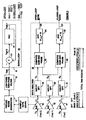
- Figure 1 illustrates a block diagram of the presently preferred embodiment to the present invention.
- the servo system under test 9 is operating with the servo loop 10 in closed loop.
- a binary pseudo-random sequence is applied to the servo by the combination of the pseudo-random noise generator 11 inputting to the low pass/high pass filter 12.
- the binary pseudo-random sequence consists of ten repeated blocks of a 1023 bit sequence, which is passed through the low pass/high pass filter, i.e., band pass filter 12, before injection into the servo 9. Simultaneously sampled measurements are taken at three points in the servo loop 10, "test,” “test 1,” and "test 2.”
- the open loop bode is computed from the gain and phase of Z/Y by averaging over the ten blocks.
- the closed loop bode is similarly computed from Z/X or can be computed directly from the quantity Z/Y as G/(1+G) where G equals Z/Y.
- test2, test1, and test signals are input into, respectively, A to D converters 15, 16, and 17, the output of which are input to the data analysis block 18.
- digital fast Fourier transforms operations are performed on the test2, test1, and test signals at blocks 19, 20, and 21.
- the output of the DFT blocks 19-21 are input, as appropriate, to gain and phase blocks 22 and 23 such that the open loop bode result 26 from the computer gain and phase block 22 and average computation block 24 is derived from the signals Z(f) and Y(f), respectively referring to the test1 and test2 transforms.
- the gain and phase bloc 23 and average block 25 yield the closed loop bode result 27 using the Z(f) and X(f) transforms of, respectively, test1 and test.
- the programmable band pass filter 12 allows the bode plots to be generated in distinct sub-octave frequency bands to eliminate aliased signal errors in the subsequent DFT processing in blocks 19-21.
- the distinct sub-octave frequency bands can later be concatenated to produce a continuous bode plot over the entire frequency range of interest. Segmenting into bands also allows different test signal amplitudes to be used for each band, optimizes the signal-to-noise ratio of the measurement, and prevents circuit saturation.
- each spectral line generated from the 1,023 bit pseudo-random noise sequence is at the exact center of the 1,023 point discrete fast Fourier transform channels, all 1,023 spectral lines are processed with total orthogonality relative to each other.
- the DFT guarantees this because all other spectral lines other than the channel center line will coincide with a "zero" of the sinX/X shaped DFT response. This produces a considerably superior measurement over techniques that use random noise generators other than pseudo-random noise sequence synced to a DFT.
- the present invention has application in any embedded system bode plot generation system, for example, on in-situ self-testing of any servo control mechanisms.
- One example in-situ system may be an on-orbit servo control mechanism where control of the servo may be maintained while the servo is under test.
- test equipment of any sort such as dynamic signal and FFT analyzers.
- FFT analyzers Other applications that may employ the present invention to advantage are test equipment of any sort such as dynamic signal and FFT analyzers.
Landscapes
- Engineering & Computer Science (AREA)
- Physics & Mathematics (AREA)
- General Physics & Mathematics (AREA)
- Automation & Control Theory (AREA)
- Computer Networks & Wireless Communication (AREA)
- Signal Processing (AREA)
- Feedback Control In General (AREA)
- Investigating Strength Of Materials By Application Of Mechanical Stress (AREA)
- Mobile Radio Communication Systems (AREA)
Claims (20)
- System, enthaltend:einen servogeregelten Mechanismus (9), der einen Regelkreis (10) hat,ein Bode-Diagrammerzeugungssystem (18), das in den Regelkreis eingebettet ist, um gleichzeitig ein Bode-Diagramm des offenen Regelkreises (26) und des geschlossenen Regelkreises (27) bereitzustellen, welches Erzeugungssystem einen Pseudozufalls-Rauschgenerator (11) einschließt, um eine Pseudozufallssequenz als ein Testsignal in den Regelkreis (10) einzuleiten, während der Regelkreis während des Tests des Systems in einem geschlossenen Zustand ist,ein programmierbares Sub-Oktav-Bandpassfilter (12), das es ermöglicht, die Bode-Diagramme in jedem einer Vielzahl von unterschiedlichen Sub-Oktav-Frequenzbändern zu erzeugen, wobei das Testsignal als ein Servoeingangssignal mit unterschiedlichen jeweiligen Amplituden für jedes der Vielzahl von Sub-Oktav-Frequenzbändern eingeleitet wird, undeinen diskrete schnelle Fourier-Transformation-Analysator (19, 20, 21), in welchem von der Pseudozufallssequenz definierte Spektrallinien mit Kanälen einer diskreten schnellen Fourier-Transformation des Analysators synchronisiert werden.
- System nach Anspruch 1, bei welchem das Bode-Diagrammerzeugungssystem (18) ferner dafür konstruiert und ausgelegt ist, sowohl einen Eingang (Test 2) in den Regelkreis als auch einen Ausgang (Test 1) des Regelkreises zu testen, um die Bode-Diagramme (26, 27) des offenen und des geschlossenen Regelkreises auf der Grundlage von Signalen sowohl von dem Eingang (Test 2) als auch dem Ausgang (Test 1) des Regelkreises bereitzustellen.
- System nach Anspruch 1, bei welchem das Bode-Diagrammerzeugungssystem (18) ferner dafür konstruiert und ausgelegt ist, einen Eingang (Test 2) in den Regelkreis (10), ein Signal (Test), das einen rückkopplungsmodifizierten Eingang in den Regelkreis darstellt, und einen Ausgang (Test 1) des Regelkreises zu testen, um die Bode-Diagramme (26, 27) des offenen und des geschlossenen Regelkreises zu erzeugen.
- System nach Anspruch 1, bei welchem der servogeregelte Mechanismus (9) eine Summiereinrichtung (13) in dem Regelkreis enthält und bei welchem das Bode-Diagrammerzeugungssystem ferner dafür konstruiert und ausgelegt ist, (A) einen Eingang (Test) in die Summiereinrichtung (13), (B) einen Ausgang (Test 2) der Summiereinrichtung und (C) einen Ausgang (Test 1) des Regelkreises zu testen, um die Bode-Diagramme (26, 27) des offenen und des geschlossenen Regelkreises bereitzustellen.
- System nach Anspruch 4, bei welchem das Bode-Diagrammerzeugungssystem (18) ein Datenanalyse-Dienstprogramm (19, 20, 21) enthält, um eine diskrete Fourier-Analyse an digitalisierten Versionen des Eingangs (Test) in die Summiereinrichtung (13), des Ausgangs (Test 2) der Summiereinrichtung (13) und des Ausgangs (Test 1) des Regelkreises (10) durchzuführen.
- System nach Anspruch 5, bei welchem das Datenanalyse-Dienstprogramm ferner dafür konstruiert und ausgelegt ist, zu berechnen:das Bode-Diagramm (26) des offenen Regelkreises, indem die digitalisierte Version des Ausgangs (Test 1) des Regelkreises durch die digitalisierte Version des Ausgangs (Test 2) der Summiereinrichtung (13) geteilt wird, unddas Bode-Diagramm (27) des geschlossenen Regelkreises, indem die digitalisierte Version des Ausgangs (Test 1) des Regelkreises (10) durch die digitalisierte Version des Eingangs (Test) der Summiereinrichtung (13) geteilt wird.
- System nach mindestens einem der Ansprüche 1 bis 6, bei welchem das Bode-Diagrammerzeugungssystem (18) ferner dafür konstruiert und ausgelegt ist, dass es so arbeitet, dass es die Bode-Diagramme (26, 27) des offenen und des geschlossenen Regelkreises bereitstellt, während der servogeregelte Mechanismus gleichzeitig die Servoregelung des getesteten Systems aufrechterhält.
- Verfahren, enthaltend die Schritte:Servoregeln eines Mechanismus (9), der einen Regelkreis (10) hat;Testen von in den Regelkreis eingebetteten Signalen während gleichzeitiger Servoregelung des Mechanismus;Erzeugen einer Pseudozufallssequenz (11);Leiten der Pseudozufallssequenz durch ein programmierbares Sub-Oktav-Bandpassfilter (12), um ein Servoeingangssignal zu erzeugen, das jeweils verschiedene Amplituden für jedes einer Vielzahl von Sub-Oktav-Frequenzbändern hat, und Spektrallinien definiert;Einleiten des Servoeingangssignals in den Regelkreis (10), während der Regelkreis während des Testens geschlossen ist; undErzeugen der Bode-Diagramme (26, 27) des offenen und des geschlossenen Regelkreises für jedes der unterschiedlichen Sub-Oktav-Frequenzbänder unter Verwendung von diskreten schnellen Fourier-Transformationen (19, 20, 21), die mit den Spektrallinien synchronisierende Kanäle haben.
- Verfahren nach Anspruch 8, bei welchem der Schritt des Testens das Testen sowohl eines Eingangs (Test) in den Regelkreis (10) als auch eines Ausgangs (Test 1) des Regelkreises einschließt, um die Bode-Diagramme (26, 27) des offenen und des geschlossenen Regelkreises auf der Grundlage von Signalen von sowohl dem Eingang als auch dem Ausgang des Regelkreises zu erzeugen.
- Verfahren nach Anspruch 8, bei welchem der Schritt des Testens das Testen sowohl eines Eingangs (Test) in den Regelkreis (10), eines Signals (Test 2), das einen rückkopplungsmodifizierten Eingang in den Regelkreis (10) darstellt, und eines Ausgangs (Test 1) aus dem Regelkreis einschließt, um die Bode-Diagramme (26, 27) des offenen und des geschlossenen Regelkreises zu erzeugen.
- Verfahren nach Anspruch 8, ferner enthaltend die Schritte:Summieren eines Eingangs (Test) in der Summiereinrichtung (13) und eines Ausgangs (Test 1) des Regelkreises (10) in einer Summiereinrichtung (13) in dem Regelkreis;Erstellen von digitalisierten Versionen des Eingangs in die Summiereinrichtung, des Ausgangs der Summiereinrichtung und des Ausgangs des Regelkreises; und Berechnen der Bode-Diagramme (26, 27) des offenen und des geschlossenen Regelkreises auf der Grundlage der digitalisierten Versionen des Eingangs (Test) in die Summiereinrichtung, des Ausgangs (Test 2) der Summiereinrichtung und des Ausgangs (Test 1) des Regelkreises (10).
- Verfahren nach Anspruch 11, ferner enthaltend den Schritt des Durchführens einer diskreten Fourier-Analyse an den digitalisierten Versionen des Eingangs (Test) in die Summiereinrichtung, des Ausgangs (Test 2) der Summiereinrichtung und des Ausgangs (Test 1) des Regelkreises (10).
- Verfahren nach Anspruch 12, bei welchem der Schritt des Berechnens ferner enthält:Berechnen des Bode-Diagramms (26) des offenen Regelkreises, indem die digitalisierte Version des Ausgangs (Test 1) des Regelkreises durch die digitalisierte Version des Ausgangs (Test 2) der Summiereinrichtung (13) geteilt wird, undBerechnen des Bode-Diagramms (27) des geschlossenen Regelkreises, indem die digitalisierte Version des Ausgangs (Test 1) des Regelkreises (10) durch die digitalisierte Version des Eingangs (Test) der Summiereinrichtung (13) geteilt wird.
- Verfahren nach Anspruch 8, ferner enthaltend:Verketten mindestens einiger der verschiedenen Sub-Oktav-Frequenzbänder, um ein kontinuierliches Bode-Diagramm über einen gesamten Frequenzbereich von Interesse zu erzeugen.
- Testvorrichtung für ein servogeregeltes Instrument, das ein Servoeingangssignal (Test), ein Instrumentenausgangssignal (Test 1) und ein rückkopplungsfehlerkompensiertes Signal (Test 2) hat, enthaltend:einen Testsignalgenerator (11), um eine Pseudozufalls-Rauschsequenz als ein Testsignal in das Instrument als das Servoeingangssignal (Test) einzuleiten, welches Servoeingangssignal Spektrallinien definiert;Testsignalerfassungsschaltungen zum Empfangen von Werten für das Servoeingangssignal, das Instrumentenausgangssignal und das rückkopplungsfehlerkompensierte Signal in geschlossenen Regelkreis-Bedingungen, während das Testsignal als das Servoeingangssignal eingeleitet wird und während das Instrument unter Servoregelung verbleibt, und zum Berechnen einer Korrekturfunktion für das Instrument in Übereinstimmung mit den erfassten Werten in Echtzeit;ein programmierbares Sub-Oktav-Bandpassfilter (12), um das Erzeugen von Bode-Diagrammen des offenen Regelkreises (26) und des geschlossenen Regelkreises (27) in jedem einer Vielzahl von verschiedenen Sub-Oktav-Frequenzbändern zu ermöglichen; undeinen Prozessor (19, 20, 21) zur diskreten schnellen Fourier-Transformation, der auf den Spektrallinien zentrierte Kanäle hat;wobei das Testsignal als das Servoeingangssignal mit jeweils verschiedenen Amplituden für jedes der Vielzahl von Sub-Oktav-Frequenzbändern eingeleitet wird.
- Testvorrichtung nach Anspruch 14, ferner dafür konstruiert und ausgelegt, dass sie die Pseudozufalls-Rauschsequenz empfängt und verarbeitet und ein Ausgangssignal von dem Filter als das Testsignal einleitet.
- Testvorrichtung nach Anspruch 16, bei welcher die Korrekturfunktion Bode-Diagramme (26, 27) einschließt.
- Testvorrichtung nach mindestens einem der Ansprüche 15 bis 17, bei welcher die Testsignalerfassungsschaltungen enthalten:Digitalisiereinrichtungen (15, 16, 17) zum Empfangen und Digitalisieren der Werte für das Servoeingangssignal (Test), das Instrumentenausgangssignal (Test 1) und das rückkopplungsfehlerkompensierte Signal (Test 2) in geschlossenen Regelkreis-Bedingungen, während das Testsignal als das Servoeingangssignal eingeleitet wird;Fourier-Transformationseinrichtungen (19, 20, 21) zum Umwandeln der Werte für das Servoeingangssignal (Test), das Instrumentenausgangssignal (Test 1) und das rückkopplungsfehlerkompensierte Signal (Test 2) in geschlossenen Regelkreis-Bedingungen, während das Testsignal als das Servoeingangssignal eingeleitet wird, in Frequenzdomänenwerte für das Servoeingangssignal (Test), das Instrumentenausgangssignal (Test 1) und das rückkopplungsfehlerkompensierte Signal (Test 2); undDatenanalyseeinrichtungen (22, 23) zum Berechnen der Korrekturfunktion, um eine Korrekturfunktion des offenen Regelkreises und eine Korrekturfunktion des geschlossenen Regelkreises in Übereinstimmung mit Frequenzdomänenwerten einzuschließen.
- Testvorrichtung nach Anspruch 18, bei welcher:die Korrekturfunktion des geschlossenen Regelkreises gemäß einer Division der Frequenzdomänenwerte des Instrumentenausgangssignals (Test 1) durch das Servoeingangssignal (Test) berechnet wird, unddie Korrekturfunktion des offenen Regelkreises gemäß einer Division der Frequenzdomänenwerte des Instrumentenausgangssignals (Test 1) durch das rückkopplungsfehlerkompensierte Signal (Test 2) berechnet wird.
- Testvorrichtung nach Anspruch 15, bei welcher die Testsignalerfassungsschaltungen dafür ausgelegt sind, Werte für das Servoeingangssignal (Test), das Instrumentenausgangssignal (Test 1) und das rückkopplungsfehlerkompensierte Signal (Test 2) in geschlossenen Regelkreis-Bedingungen durch Empfangen von Gruppen von Stichproben des Servoeingangssignals (Test), des Instrumentenausgangssignals (Test 1) bzw. des rückkopplungsfehlerkompensierten Signals (Test 2) jeweils in geschlossenen Regelkreis-Bedingungen zu empfangen.
Applications Claiming Priority (2)
| Application Number | Priority Date | Filing Date | Title |
|---|---|---|---|
| US94965 | 2002-03-12 | ||
| US10/094,965 US6895352B2 (en) | 2002-03-12 | 2002-03-12 | Simultaneous rapid open and closed loop bode plot measurement using a binary pseudo-random sequence |
Publications (2)
| Publication Number | Publication Date |
|---|---|
| EP1345102A1 EP1345102A1 (de) | 2003-09-17 |
| EP1345102B1 true EP1345102B1 (de) | 2007-03-21 |
Family
ID=27765384
Family Applications (1)
| Application Number | Title | Priority Date | Filing Date |
|---|---|---|---|
| EP03005240A Expired - Lifetime EP1345102B1 (de) | 2002-03-12 | 2003-03-10 | Gleichzeitige und schnelle Berechnung von Bode-Diagrammen im offenen und geschlossenen Regelkreis mit Hilfe einer binären Pseudozufallssequenz |
Country Status (4)
| Country | Link |
|---|---|
| US (1) | US6895352B2 (de) |
| EP (1) | EP1345102B1 (de) |
| AT (1) | ATE357685T1 (de) |
| DE (1) | DE60312578T2 (de) |
Families Citing this family (5)
| Publication number | Priority date | Publication date | Assignee | Title |
|---|---|---|---|---|
| US6895352B2 (en) * | 2002-03-12 | 2005-05-17 | Itt Manufacturing Enterprises, Inc. | Simultaneous rapid open and closed loop bode plot measurement using a binary pseudo-random sequence |
| EP1706801A1 (de) * | 2004-01-23 | 2006-10-04 | GSI Group Corporation | System und verfahren zur diagnostizierung einer steuerung in einem motorsystem mit begrenzter drehung |
| TW200637181A (en) * | 2005-03-02 | 2006-10-16 | Koninkl Philips Electronics Nv | Methods and apparatuses for tuning filters |
| US9909564B2 (en) | 2010-12-23 | 2018-03-06 | Vestas Wind Systems A/S | Supervision of controller instability in a wind turbine |
| US11165372B2 (en) * | 2017-09-13 | 2021-11-02 | Rockwell Automation Technologies, Inc. | Method and apparatus to characterize loads in a linear synchronous motor system |
Family Cites Families (16)
| Publication number | Priority date | Publication date | Assignee | Title |
|---|---|---|---|---|
| US4067060A (en) | 1976-07-06 | 1978-01-03 | Canadian Patents And Development Limited | Transfer function measurement |
| US4093988A (en) | 1976-11-08 | 1978-06-06 | General Electric Company | High speed frequency response measurement |
| US4306113A (en) * | 1979-11-23 | 1981-12-15 | Morton Roger R A | Method and equalization of home audio systems |
| FR2508649A1 (fr) | 1981-06-30 | 1982-12-31 | Ecole Superieure Electricite | Procede et dispositif pour la caracterisation de systemes par analyse spectrale |
| US5446648A (en) | 1992-02-28 | 1995-08-29 | Abramovitch; Daniel Y. | Determination of open loop responses from closed loop measurements |
| US5406496A (en) | 1992-07-20 | 1995-04-11 | Recon/Optical, Inc. | Adaptive digital controller with automatic plant tuning |
| US5517594A (en) | 1994-10-17 | 1996-05-14 | Relman, Inc. | Thermal reactor optimization |
| US5687733A (en) | 1995-10-26 | 1997-11-18 | Baxter International Inc. | System and method for estimating cardiac output |
| US5909661A (en) | 1997-05-30 | 1999-06-01 | Hewlett-Packard Company | Method and apparatus for decomposing drive error signal noise sources |
| US5880415A (en) | 1997-12-22 | 1999-03-09 | Otis Elevator Company | Automatic calibration of current regulator control compensation for an elevator motor drive with locked rotor |
| US5929400A (en) | 1997-12-22 | 1999-07-27 | Otis Elevator Company | Self commissioning controller for field-oriented elevator motor/drive system |
| US6204988B1 (en) | 1998-08-24 | 2001-03-20 | Western Digital Corporation | Disk drive capable of autonomously evaluating and adapting the frequency response of its servo control system |
| US6278898B1 (en) | 1999-04-07 | 2001-08-21 | Voyan Technology | Model error bounds for identification of stochastic models for control design |
| US6198246B1 (en) * | 1999-08-19 | 2001-03-06 | Siemens Energy & Automation, Inc. | Method and apparatus for tuning control system parameters |
| US6622099B2 (en) * | 2000-08-14 | 2003-09-16 | Kollmorgen Corporation | Frequency domain auto-tune for an internal motor controller |
| US6895352B2 (en) * | 2002-03-12 | 2005-05-17 | Itt Manufacturing Enterprises, Inc. | Simultaneous rapid open and closed loop bode plot measurement using a binary pseudo-random sequence |
-
2002
- 2002-03-12 US US10/094,965 patent/US6895352B2/en not_active Expired - Fee Related
-
2003
- 2003-03-10 EP EP03005240A patent/EP1345102B1/de not_active Expired - Lifetime
- 2003-03-10 DE DE60312578T patent/DE60312578T2/de not_active Expired - Lifetime
- 2003-03-10 AT AT03005240T patent/ATE357685T1/de not_active IP Right Cessation
Non-Patent Citations (2)
| Title |
|---|
| "Control System Toolbox 5", 2000, THE MATHWORKS, INC. * |
| OLIS RUBIN: "The Design of Automatic Control Systems, Chapter 6", 1986, ARTECH HOUSE, INC. * |
Also Published As
| Publication number | Publication date |
|---|---|
| DE60312578D1 (de) | 2007-05-03 |
| ATE357685T1 (de) | 2007-04-15 |
| EP1345102A1 (de) | 2003-09-17 |
| DE60312578T2 (de) | 2007-12-06 |
| US6895352B2 (en) | 2005-05-17 |
| US20030176983A1 (en) | 2003-09-18 |
Similar Documents
| Publication | Publication Date | Title |
|---|---|---|
| US5162723A (en) | Sampling signal analyzer | |
| Carvalho et al. | Multisine signals for wireless system test and design [application notes] | |
| Dallet et al. | Dynamic characterisation of analogue-to-digital converters | |
| RU2516201C2 (ru) | Способ и система мониторинга электромагнитных помех во временной области | |
| CN101702018A (zh) | 一种大调制带宽线性调频信号频响校准方法 | |
| US6208946B1 (en) | High speed fourier transform apparatus | |
| US20040122608A1 (en) | DFT leakage removal for non-coherently sampled signals | |
| DE10392151B4 (de) | Verfahren und Vorrichtung zur Erfassung im Frequenzbereich basierend auf einer Zeitbereichsmessung | |
| US10735036B1 (en) | Method for measuring frequency offset between an RF transmitter and a test receiver | |
| JP2005509890A (ja) | 波形を測定するための方法および装置 | |
| US20040098215A1 (en) | Method for the rapid estimation of figures of merit for multiple devices based on nonlinear modeling | |
| US5051916A (en) | Stimulus signal generation method to maximize dynamic range in frequency response function calculations | |
| CN115015818A (zh) | 一种用于矢量参数测试的相位校准装置定标方法及装置 | |
| US6895352B2 (en) | Simultaneous rapid open and closed loop bode plot measurement using a binary pseudo-random sequence | |
| US20090290658A1 (en) | Multi-Pulse Signal Generator Based on a Sawtooth Chirp | |
| CN113702701B (zh) | 一种基于梳状波信号的幅相特性测量方法 | |
| Ebbeni et al. | A flexible approach on pulsed wire magnetic measurement method | |
| CN117761393B (zh) | 一种时域信号的获取方法及装置 | |
| Daponte et al. | A cyclostationarity-based method for jitter measurement in waveform recorders | |
| CN117706213A (zh) | 一种电磁继电器抗电磁脉冲干扰测试方法、装置和设备 | |
| CN114236454B (zh) | 一种宽频电阻分压器的误差校准方法及装置 | |
| CN117665423A (zh) | 相位噪声测量装置和方法 | |
| Liu et al. | Scanning of random fields using blind source separation | |
| Ryabov et al. | From chaotic to 1/f processes in solar mcw-bursts. | |
| US10788553B2 (en) | Nuclear magnetic resonance apparatus |
Legal Events
| Date | Code | Title | Description |
|---|---|---|---|
| PUAI | Public reference made under article 153(3) epc to a published international application that has entered the european phase |
Free format text: ORIGINAL CODE: 0009012 |
|
| AK | Designated contracting states |
Kind code of ref document: A1 Designated state(s): AT BE BG CH CY CZ DE DK EE ES FI FR GB GR HU IE IT LI LU MC NL PT RO SE SI SK TR |
|
| AX | Request for extension of the european patent |
Extension state: AL LT LV MK |
|
| 17P | Request for examination filed |
Effective date: 20040317 |
|
| AKX | Designation fees paid |
Designated state(s): AT BE BG CH CY CZ DE DK EE ES FI FR GB GR HU IE IT LI LU MC NL PT RO SE SI SK TR |
|
| 17Q | First examination report despatched |
Effective date: 20050208 |
|
| GRAP | Despatch of communication of intention to grant a patent |
Free format text: ORIGINAL CODE: EPIDOSNIGR1 |
|
| GRAS | Grant fee paid |
Free format text: ORIGINAL CODE: EPIDOSNIGR3 |
|
| GRAA | (expected) grant |
Free format text: ORIGINAL CODE: 0009210 |
|
| AK | Designated contracting states |
Kind code of ref document: B1 Designated state(s): AT BE BG CH CY CZ DE DK EE ES FI FR GB GR HU IE IT LI LU MC NL PT RO SE SI SK TR |
|
| PG25 | Lapsed in a contracting state [announced via postgrant information from national office to epo] |
Ref country code: NL Free format text: LAPSE BECAUSE OF FAILURE TO SUBMIT A TRANSLATION OF THE DESCRIPTION OR TO PAY THE FEE WITHIN THE PRESCRIBED TIME-LIMIT Effective date: 20070321 Ref country code: FI Free format text: LAPSE BECAUSE OF FAILURE TO SUBMIT A TRANSLATION OF THE DESCRIPTION OR TO PAY THE FEE WITHIN THE PRESCRIBED TIME-LIMIT Effective date: 20070321 Ref country code: LI Free format text: LAPSE BECAUSE OF FAILURE TO SUBMIT A TRANSLATION OF THE DESCRIPTION OR TO PAY THE FEE WITHIN THE PRESCRIBED TIME-LIMIT Effective date: 20070321 Ref country code: BE Free format text: LAPSE BECAUSE OF FAILURE TO SUBMIT A TRANSLATION OF THE DESCRIPTION OR TO PAY THE FEE WITHIN THE PRESCRIBED TIME-LIMIT Effective date: 20070321 Ref country code: CH Free format text: LAPSE BECAUSE OF FAILURE TO SUBMIT A TRANSLATION OF THE DESCRIPTION OR TO PAY THE FEE WITHIN THE PRESCRIBED TIME-LIMIT Effective date: 20070321 Ref country code: SI Free format text: LAPSE BECAUSE OF FAILURE TO SUBMIT A TRANSLATION OF THE DESCRIPTION OR TO PAY THE FEE WITHIN THE PRESCRIBED TIME-LIMIT Effective date: 20070321 Ref country code: AT Free format text: LAPSE BECAUSE OF FAILURE TO SUBMIT A TRANSLATION OF THE DESCRIPTION OR TO PAY THE FEE WITHIN THE PRESCRIBED TIME-LIMIT Effective date: 20070321 |
|
| REG | Reference to a national code |
Ref country code: GB Ref legal event code: FG4D |
|
| REG | Reference to a national code |
Ref country code: CH Ref legal event code: EP |
|
| REF | Corresponds to: |
Ref document number: 60312578 Country of ref document: DE Date of ref document: 20070503 Kind code of ref document: P |
|
| REG | Reference to a national code |
Ref country code: IE Ref legal event code: FG4D |
|
| PG25 | Lapsed in a contracting state [announced via postgrant information from national office to epo] |
Ref country code: SE Free format text: LAPSE BECAUSE OF FAILURE TO SUBMIT A TRANSLATION OF THE DESCRIPTION OR TO PAY THE FEE WITHIN THE PRESCRIBED TIME-LIMIT Effective date: 20070621 |
|
| PG25 | Lapsed in a contracting state [announced via postgrant information from national office to epo] |
Ref country code: ES Free format text: LAPSE BECAUSE OF FAILURE TO SUBMIT A TRANSLATION OF THE DESCRIPTION OR TO PAY THE FEE WITHIN THE PRESCRIBED TIME-LIMIT Effective date: 20070702 |
|
| ET | Fr: translation filed | ||
| PG25 | Lapsed in a contracting state [announced via postgrant information from national office to epo] |
Ref country code: PT Free format text: LAPSE BECAUSE OF FAILURE TO SUBMIT A TRANSLATION OF THE DESCRIPTION OR TO PAY THE FEE WITHIN THE PRESCRIBED TIME-LIMIT Effective date: 20070821 |
|
| REG | Reference to a national code |
Ref country code: CH Ref legal event code: PL |
|
| NLV1 | Nl: lapsed or annulled due to failure to fulfill the requirements of art. 29p and 29m of the patents act | ||
| PG25 | Lapsed in a contracting state [announced via postgrant information from national office to epo] |
Ref country code: SK Free format text: LAPSE BECAUSE OF FAILURE TO SUBMIT A TRANSLATION OF THE DESCRIPTION OR TO PAY THE FEE WITHIN THE PRESCRIBED TIME-LIMIT Effective date: 20070321 |
|
| PG25 | Lapsed in a contracting state [announced via postgrant information from national office to epo] |
Ref country code: CZ Free format text: LAPSE BECAUSE OF FAILURE TO SUBMIT A TRANSLATION OF THE DESCRIPTION OR TO PAY THE FEE WITHIN THE PRESCRIBED TIME-LIMIT Effective date: 20070321 Ref country code: RO Free format text: LAPSE BECAUSE OF FAILURE TO SUBMIT A TRANSLATION OF THE DESCRIPTION OR TO PAY THE FEE WITHIN THE PRESCRIBED TIME-LIMIT Effective date: 20070321 |
|
| PLBE | No opposition filed within time limit |
Free format text: ORIGINAL CODE: 0009261 |
|
| STAA | Information on the status of an ep patent application or granted ep patent |
Free format text: STATUS: NO OPPOSITION FILED WITHIN TIME LIMIT |
|
| PG25 | Lapsed in a contracting state [announced via postgrant information from national office to epo] |
Ref country code: DK Free format text: LAPSE BECAUSE OF FAILURE TO SUBMIT A TRANSLATION OF THE DESCRIPTION OR TO PAY THE FEE WITHIN THE PRESCRIBED TIME-LIMIT Effective date: 20070321 |
|
| 26N | No opposition filed |
Effective date: 20071227 |
|
| PG25 | Lapsed in a contracting state [announced via postgrant information from national office to epo] |
Ref country code: GR Free format text: LAPSE BECAUSE OF FAILURE TO SUBMIT A TRANSLATION OF THE DESCRIPTION OR TO PAY THE FEE WITHIN THE PRESCRIBED TIME-LIMIT Effective date: 20070622 |
|
| PG25 | Lapsed in a contracting state [announced via postgrant information from national office to epo] |
Ref country code: MC Free format text: LAPSE BECAUSE OF NON-PAYMENT OF DUE FEES Effective date: 20080331 |
|
| PG25 | Lapsed in a contracting state [announced via postgrant information from national office to epo] |
Ref country code: IE Free format text: LAPSE BECAUSE OF NON-PAYMENT OF DUE FEES Effective date: 20080310 Ref country code: EE Free format text: LAPSE BECAUSE OF FAILURE TO SUBMIT A TRANSLATION OF THE DESCRIPTION OR TO PAY THE FEE WITHIN THE PRESCRIBED TIME-LIMIT Effective date: 20070321 |
|
| PG25 | Lapsed in a contracting state [announced via postgrant information from national office to epo] |
Ref country code: CY Free format text: LAPSE BECAUSE OF FAILURE TO SUBMIT A TRANSLATION OF THE DESCRIPTION OR TO PAY THE FEE WITHIN THE PRESCRIBED TIME-LIMIT Effective date: 20070321 |
|
| PG25 | Lapsed in a contracting state [announced via postgrant information from national office to epo] |
Ref country code: BG Free format text: LAPSE BECAUSE OF FAILURE TO SUBMIT A TRANSLATION OF THE DESCRIPTION OR TO PAY THE FEE WITHIN THE PRESCRIBED TIME-LIMIT Effective date: 20070621 Ref country code: IT Free format text: LAPSE BECAUSE OF NON-PAYMENT OF DUE FEES Effective date: 20080310 |
|
| PG25 | Lapsed in a contracting state [announced via postgrant information from national office to epo] |
Ref country code: HU Free format text: LAPSE BECAUSE OF FAILURE TO SUBMIT A TRANSLATION OF THE DESCRIPTION OR TO PAY THE FEE WITHIN THE PRESCRIBED TIME-LIMIT Effective date: 20070922 Ref country code: LU Free format text: LAPSE BECAUSE OF NON-PAYMENT OF DUE FEES Effective date: 20080310 |
|
| PG25 | Lapsed in a contracting state [announced via postgrant information from national office to epo] |
Ref country code: TR Free format text: LAPSE BECAUSE OF FAILURE TO SUBMIT A TRANSLATION OF THE DESCRIPTION OR TO PAY THE FEE WITHIN THE PRESCRIBED TIME-LIMIT Effective date: 20070321 |
|
| REG | Reference to a national code |
Ref country code: GB Ref legal event code: 732E Free format text: REGISTERED BETWEEN 20120906 AND 20120912 |
|
| REG | Reference to a national code |
Ref country code: FR Ref legal event code: CD Owner name: EXELIS INC., US Effective date: 20120912 Ref country code: FR Ref legal event code: TP Owner name: EXELIS INC., US Effective date: 20120912 |
|
| REG | Reference to a national code |
Ref country code: DE Ref legal event code: R082 Ref document number: 60312578 Country of ref document: DE Representative=s name: PATENTANWAELTE MAGENBAUER & KOLLEGEN, DE Ref country code: DE Ref legal event code: R082 Ref document number: 60312578 Country of ref document: DE Representative=s name: PATENTANWAELTE MAGENBAUER & KOLLEGEN PARTNERSC, DE |
|
| PGFP | Annual fee paid to national office [announced via postgrant information from national office to epo] |
Ref country code: DE Payment date: 20140520 Year of fee payment: 12 |
|
| REG | Reference to a national code |
Ref country code: FR Ref legal event code: PLFP Year of fee payment: 13 |
|
| PGFP | Annual fee paid to national office [announced via postgrant information from national office to epo] |
Ref country code: IT Payment date: 20150324 Year of fee payment: 13 |
|
| PGFP | Annual fee paid to national office [announced via postgrant information from national office to epo] |
Ref country code: GB Payment date: 20150327 Year of fee payment: 13 Ref country code: FR Payment date: 20150317 Year of fee payment: 13 |
|
| REG | Reference to a national code |
Ref country code: DE Ref legal event code: R119 Ref document number: 60312578 Country of ref document: DE |
|
| PG25 | Lapsed in a contracting state [announced via postgrant information from national office to epo] |
Ref country code: DE Free format text: LAPSE BECAUSE OF NON-PAYMENT OF DUE FEES Effective date: 20151001 |
|
| GBPC | Gb: european patent ceased through non-payment of renewal fee |
Effective date: 20160310 |
|
| REG | Reference to a national code |
Ref country code: FR Ref legal event code: ST Effective date: 20161130 |
|
| PG25 | Lapsed in a contracting state [announced via postgrant information from national office to epo] |
Ref country code: FR Free format text: LAPSE BECAUSE OF NON-PAYMENT OF DUE FEES Effective date: 20160331 Ref country code: GB Free format text: LAPSE BECAUSE OF NON-PAYMENT OF DUE FEES Effective date: 20160310 |
|
| PG25 | Lapsed in a contracting state [announced via postgrant information from national office to epo] |
Ref country code: IT Free format text: LAPSE BECAUSE OF NON-PAYMENT OF DUE FEES Effective date: 20160310 |