EP1344964A2 - Procédé et dispositifs de contrôle des passages montants dans une transmission automatique ou automatisée - Google Patents
Procédé et dispositifs de contrôle des passages montants dans une transmission automatique ou automatisée Download PDFInfo
- Publication number
- EP1344964A2 EP1344964A2 EP03290643A EP03290643A EP1344964A2 EP 1344964 A2 EP1344964 A2 EP 1344964A2 EP 03290643 A EP03290643 A EP 03290643A EP 03290643 A EP03290643 A EP 03290643A EP 1344964 A2 EP1344964 A2 EP 1344964A2
- Authority
- EP
- European Patent Office
- Prior art keywords
- speed
- transmission
- nmot
- engine
- engine speed
- Prior art date
- Legal status (The legal status is an assumption and is not a legal conclusion. Google has not performed a legal analysis and makes no representation as to the accuracy of the status listed.)
- Granted
Links
Images

Classifications
-
- F—MECHANICAL ENGINEERING; LIGHTING; HEATING; WEAPONS; BLASTING
- F16—ENGINEERING ELEMENTS AND UNITS; GENERAL MEASURES FOR PRODUCING AND MAINTAINING EFFECTIVE FUNCTIONING OF MACHINES OR INSTALLATIONS; THERMAL INSULATION IN GENERAL
- F16H—GEARING
- F16H61/00—Control functions within control units of change-speed- or reversing-gearings for conveying rotary motion ; Control of exclusively fluid gearing, friction gearing, gearings with endless flexible members or other particular types of gearing
- F16H61/02—Control functions within control units of change-speed- or reversing-gearings for conveying rotary motion ; Control of exclusively fluid gearing, friction gearing, gearings with endless flexible members or other particular types of gearing characterised by the signals used
- F16H61/0202—Control functions within control units of change-speed- or reversing-gearings for conveying rotary motion ; Control of exclusively fluid gearing, friction gearing, gearings with endless flexible members or other particular types of gearing characterised by the signals used the signals being electric
- F16H61/0204—Control functions within control units of change-speed- or reversing-gearings for conveying rotary motion ; Control of exclusively fluid gearing, friction gearing, gearings with endless flexible members or other particular types of gearing characterised by the signals used the signals being electric for gearshift control, e.g. control functions for performing shifting or generation of shift signal
- F16H61/0213—Control functions within control units of change-speed- or reversing-gearings for conveying rotary motion ; Control of exclusively fluid gearing, friction gearing, gearings with endless flexible members or other particular types of gearing characterised by the signals used the signals being electric for gearshift control, e.g. control functions for performing shifting or generation of shift signal characterised by the method for generating shift signals
-
- F—MECHANICAL ENGINEERING; LIGHTING; HEATING; WEAPONS; BLASTING
- F16—ENGINEERING ELEMENTS AND UNITS; GENERAL MEASURES FOR PRODUCING AND MAINTAINING EFFECTIVE FUNCTIONING OF MACHINES OR INSTALLATIONS; THERMAL INSULATION IN GENERAL
- F16H—GEARING
- F16H61/00—Control functions within control units of change-speed- or reversing-gearings for conveying rotary motion ; Control of exclusively fluid gearing, friction gearing, gearings with endless flexible members or other particular types of gearing
- F16H61/02—Control functions within control units of change-speed- or reversing-gearings for conveying rotary motion ; Control of exclusively fluid gearing, friction gearing, gearings with endless flexible members or other particular types of gearing characterised by the signals used
- F16H61/0202—Control functions within control units of change-speed- or reversing-gearings for conveying rotary motion ; Control of exclusively fluid gearing, friction gearing, gearings with endless flexible members or other particular types of gearing characterised by the signals used the signals being electric
- F16H61/0204—Control functions within control units of change-speed- or reversing-gearings for conveying rotary motion ; Control of exclusively fluid gearing, friction gearing, gearings with endless flexible members or other particular types of gearing characterised by the signals used the signals being electric for gearshift control, e.g. control functions for performing shifting or generation of shift signal
- F16H61/0213—Control functions within control units of change-speed- or reversing-gearings for conveying rotary motion ; Control of exclusively fluid gearing, friction gearing, gearings with endless flexible members or other particular types of gearing characterised by the signals used the signals being electric for gearshift control, e.g. control functions for performing shifting or generation of shift signal characterised by the method for generating shift signals
- F16H2061/0216—Calculation or estimation of post shift values for different gear ratios, e.g. by using engine performance tables
Definitions
- the present invention relates to automatic transmissions or automated with stepped reports, and more precisely the management of passages of speeds.
- the subject of this invention is a method for controlling upshift changes in automatic transmission or automated, according to laws of passage established as a function of the speed of movement of vehicle and engine load.
- gear changes are triggered depending on the speed of the vehicle and engine load. These speed and load criteria are taken into account in gearshift laws, materialized by curves in a coordinate plane Vehicle speed / Variable from engine load (throttle, accelerator pedal position, power, etc.), and gear changes are triggered when the point of transmission operation crosses one of these curves.
- the passage curves amounts and descending passages are offset, so as to avoid “Pumping phenomenon", ie the instability of the proximity relationship passage curves.
- the present invention aims to improve the delivery of change amount reporting and optimizing the application of the amount crossing laws in an automatic or automated transmission.
- the ascending passages be triggered when the engine speed reaches a value determined from laws of passage and the variation of regime planned during the phase of disengagement of the transmission.
- the variation of the planned regime is a function of the ratio of the transmission and the engine speed derivative.
- This variation in the planned engine speed is for example deducted, of a cartography established by development.
- the curve (1) is a downflow curve (N / N-1), and the curve (2) is a rising passage curve (N / N + 1).
- N / N-1 a downflow curve
- N / N + 1 a rising passage curve
- These curves aim to perform the passages at vehicle speeds even higher than the load of the engine is high, within the maximum permitted engine speed, sometimes called "breaker". Furthermore, the offset between the two curves avoids the so-called “pumping” phenomena mentioned above.
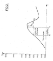
- FIG. 2 shows the evolution of the engine speed N word in rpm during an ascending passage, for example a 1/2 passage.
- the value of the engine speed at t o is approximately 3000 rpm.
- the curve of the engine speed N word highlights the poor management of the waypoint in the absence of any specific provision. Indeed, if the shift is triggered when the actual speed of the vehicle is that which is desired by the shift law, the shift takes place (due to the clutch release time), beyond this desired speed, which is 3000 rpm in this example.
- the programmed passing law is therefore not respected due to the increase in the engine speed ⁇ Nmot , during declutching, between the setpoint top at t o , and the effective transition to t 1 .
- the invention proposes to take into account the variation in engine speed predictable during the declutching phase of the rising passage, so as to launch the passage setpoint top, not at the moment when the engine speed N word reaches the maximum speed. authorized according to the load of the engine and the established speed, but at the moment when it reaches this speed minus the variation of speed planned during the declutching phase.
- the upshifts are triggered when the engine speed N word reaches a value determined from the shift laws and the speed variation ⁇ Nmot expected during the disengaging phase of the transmission.
- the variation in speed ⁇ Nmot expected depends on the ratio of the transmission and the derivative of the engine speed.
- the value of the engine speed N word normally given by the control unit, is therefore derived, and this derivative is advantageously subject to conventional first order digital filtering.
- the variation of the planned engine speed ⁇ Nmot can be deduced from a map established by focusing.
- the planned speed variation can be evaluated at any time by interpolation of the mapping, before being subtracted from the maximum speed N max authorized by the shift laws as a function of the current ratio and the load of the motor ⁇ .
- the engine speed N word is therefore compared at each instant to a threshold N max - ⁇ Nmot , this threshold being equal to the engine speed N max at the maximum authorized speed as a function of the engine load ⁇ on the current ratio, minus the planned speed increase ⁇ Nmot .
- the start of passage peak is therefore given as soon as N word > N max - ⁇ Nmot .
Landscapes
- Engineering & Computer Science (AREA)
- General Engineering & Computer Science (AREA)
- Mechanical Engineering (AREA)
- Control Of Transmission Device (AREA)
Abstract
Description
- la figure 1 rappelle le principe connu des lois de passages de vitesses, et
- la figure 2 illustre le procédé de commande de l'invention.
Claims (8)
- Procédé de commande des changements de rapports montants d'une transmission automatique ou automatisée selon des lois de passage établies en fonction de la vitesse de déplacement du véhicule et de la charge du moteur (α), caractérisé en ce que les passages montants sont déclenchés lorsque le régime moteur (Nmot) atteint une valeur (Nmax) déterminée à partir des lois de passage et de la variation de régime (ΔNmot) prévue pendant la phase de débrayage de la transmission.
- Procédé de commande selon la revendication 1, caractérisé en ce que la variation du régime (ΔNmot) prévue, est fonction du rapport de la transmission et de la dérivée du régime moteur (Nmot).
- Procédé de commande selon la revendication 1, ou 2 , caractérisé en ce que, la variation du régime moteur prévue (ΔNmot) est déduite d'une cartographie établie par mise au point.
- Procédé de commande selon la revendication 1, 2 ou 3, caractérisé en ce que le régime moteur Nmot est comparé à un seuil (Nmax- ΔNmot), égal au régime du moteur (Nmax) à la vitesse maximum autorisée sur le rapport courant, en fonction de la charge moteur (α), et en tenant compte de l'augmentation de régime ΔNmot prévue pendant le passage.
- Calculateur de transmission, caractérisé en ce qu'il déclenche les passages montants conformément à l'une des revendications précédentes.
- Transmission automatique à passages sous couple, caractérisée en ce qu'elle comporte un calculateur conforme à la revendication 5.
- Transmission automatisée à rupture de couple, caractérisée en ce qu'elle comporte un calculateur conforme à la revendication 5.
- Véhicule automobile, caractérisé en ce qu'il comporte une transmission conforme à la revendication 6 ou 7.
Applications Claiming Priority (2)
| Application Number | Priority Date | Filing Date | Title |
|---|---|---|---|
| FR0203239 | 2002-03-15 | ||
| FR0203239A FR2837254B1 (fr) | 2002-03-15 | 2002-03-15 | Procede et dispositifs de controle des passages montants dans une transmission automatique ou automatisee |
Publications (3)
| Publication Number | Publication Date |
|---|---|
| EP1344964A2 true EP1344964A2 (fr) | 2003-09-17 |
| EP1344964A3 EP1344964A3 (fr) | 2010-04-28 |
| EP1344964B1 EP1344964B1 (fr) | 2011-05-04 |
Family
ID=27763745
Family Applications (1)
| Application Number | Title | Priority Date | Filing Date |
|---|---|---|---|
| EP03290643A Expired - Lifetime EP1344964B1 (fr) | 2002-03-15 | 2003-03-14 | Procédé et dispositifs de contrôle des passages montants dans une transmission automatique ou automatisée |
Country Status (4)
| Country | Link |
|---|---|
| EP (1) | EP1344964B1 (fr) |
| AT (1) | ATE508301T1 (fr) |
| DE (1) | DE60336949D1 (fr) |
| FR (1) | FR2837254B1 (fr) |
Cited By (1)
| Publication number | Priority date | Publication date | Assignee | Title |
|---|---|---|---|---|
| WO2006087626A3 (fr) * | 2005-02-18 | 2007-01-25 | Ferrari Spa | Procede et unite de changement de vitesse dans une transmission servo-assistee |
Family Cites Families (2)
| Publication number | Priority date | Publication date | Assignee | Title |
|---|---|---|---|---|
| US5166879A (en) * | 1990-12-03 | 1992-11-24 | Ford Motor Company | Load condition preemption of scheduled gearshifts in an automatic transmission |
| FR2765651B1 (fr) * | 1997-07-02 | 1999-09-24 | Renault | Procede de commande des changements de rapports d'une transmission automatique |
-
2002
- 2002-03-15 FR FR0203239A patent/FR2837254B1/fr not_active Expired - Fee Related
-
2003
- 2003-03-14 EP EP03290643A patent/EP1344964B1/fr not_active Expired - Lifetime
- 2003-03-14 DE DE60336949T patent/DE60336949D1/de not_active Expired - Lifetime
- 2003-03-14 AT AT03290643T patent/ATE508301T1/de not_active IP Right Cessation
Cited By (2)
| Publication number | Priority date | Publication date | Assignee | Title |
|---|---|---|---|---|
| WO2006087626A3 (fr) * | 2005-02-18 | 2007-01-25 | Ferrari Spa | Procede et unite de changement de vitesse dans une transmission servo-assistee |
| US8229636B2 (en) | 2005-02-18 | 2012-07-24 | Ferrari S.P.A. | Method and unit for shifting gear in a power-assist transmission |
Also Published As
| Publication number | Publication date |
|---|---|
| FR2837254B1 (fr) | 2004-07-09 |
| EP1344964B1 (fr) | 2011-05-04 |
| FR2837254A1 (fr) | 2003-09-19 |
| ATE508301T1 (de) | 2011-05-15 |
| EP1344964A3 (fr) | 2010-04-28 |
| DE60336949D1 (de) | 2011-06-16 |
Similar Documents
| Publication | Publication Date | Title |
|---|---|---|
| FR2809353A1 (fr) | Ligne motrice pour vehicule automobile | |
| FR2742502A1 (fr) | Vehicule automobile a systeme automatise de transmission de couple | |
| FR2622848A1 (fr) | Dispositif pour l'actionnement automatique d'un embrayage a friction | |
| FR2706376A1 (fr) | Procédé de commande automatique d'un embrayage pour déclencher et interrompre des phases de roulement en poussée dans un véhicule automobile. | |
| FR2765160A1 (fr) | Commande pour la ligne motrice d'un vehicule automobile | |
| EP0814969A1 (fr) | Systeme de commande pour boite de vitesses mecanique automatisee | |
| FR3074534A1 (fr) | Procede de controle d’un moteur de vehicule automobile | |
| FR2809059A1 (fr) | Procede et dispositif de commande d'une unite motrice d'un vehicule automobile | |
| EP0819227A2 (fr) | Systeme a boite de vitesses mecanique robotisee comprenant des moyens de commande perfectionnes a l'arret du vehicule | |
| EP1344964B1 (fr) | Procédé et dispositifs de contrôle des passages montants dans une transmission automatique ou automatisée | |
| EP3292032B1 (fr) | Procede de gestion des pentes de l'agrement preventif en deceleration | |
| FR2658564A1 (fr) | Dispositif pour le controle unifie du moteur et de la transmission automatique dans un vehicule automobile. | |
| US6929581B2 (en) | Downshifting time torque-down control device and method | |
| EP0853017A2 (fr) | Procédé et dispositif de commande pour véhicule | |
| FR2697784A1 (fr) | Procédé et dispositif de commande pour augmenter le ralenti d'un véhicule marchant au point mort. | |
| FR2846606A1 (fr) | Procede de regulation de la vitesse d'un vehicule | |
| EP3287672A1 (fr) | Procede de controle d'un couple moteur d'un vehicule, notamment automobile | |
| EP1547849B1 (fr) | Dispositif de commande d'une boîte de vitesses automatisée destiné à améliorer la qualité des passages montants des vitesses sous faible couple du moteur | |
| EP4069540B1 (fr) | Procede de compensation d'erreurs de realisation de couple d'un moteur thermique dans une chaine de traction hybride | |
| EP1576306B1 (fr) | Procede et un systeme de commande d'une transmission automatique | |
| EP1344963B1 (fr) | Procédé et dispositifs de contrôle des changements de rapport d'une transmission automatique ou automatisee | |
| FR2834034A1 (fr) | Procede de commande d'une transmission automatisee a rapports etages | |
| EP0932777B1 (fr) | Procede de controle du couple d'entree d'une transmission | |
| FR3074535B1 (fr) | Procede de controle d’un moteur de vehicule automobile | |
| FR2783587A1 (fr) | Procede et dispositif pour une operation de retrogradation d'une boite de vitesses de vehicule automobile |
Legal Events
| Date | Code | Title | Description |
|---|---|---|---|
| PUAI | Public reference made under article 153(3) epc to a published international application that has entered the european phase |
Free format text: ORIGINAL CODE: 0009012 |
|
| AK | Designated contracting states |
Kind code of ref document: A2 Designated state(s): AT BE BG CH CY CZ DE DK EE ES FI FR GB GR HU IE IT LI LU MC NL PT RO SE SI SK TR |
|
| AX | Request for extension of the european patent |
Extension state: AL LT LV MK |
|
| PUAL | Search report despatched |
Free format text: ORIGINAL CODE: 0009013 |
|
| AK | Designated contracting states |
Kind code of ref document: A3 Designated state(s): AT BE BG CH CY CZ DE DK EE ES FI FR GB GR HU IE IT LI LU MC NL PT RO SE SI SK TR |
|
| AX | Request for extension of the european patent |
Extension state: AL LT LV MK |
|
| RIC1 | Information provided on ipc code assigned before grant |
Ipc: F16H 59/44 20060101AFI20100322BHEP |
|
| 17P | Request for examination filed |
Effective date: 20100518 |
|
| GRAP | Despatch of communication of intention to grant a patent |
Free format text: ORIGINAL CODE: EPIDOSNIGR1 |
|
| RIC1 | Information provided on ipc code assigned before grant |
Ipc: F16H 59/44 20060101AFI20101020BHEP Ipc: F16H 59/74 20060101ALI20101020BHEP Ipc: F16H 61/02 20060101ALI20101020BHEP |
|
| AKX | Designation fees paid |
Designated state(s): AT BE BG CH CY CZ DE DK EE ES FI FR GB GR HU IE IT LI LU MC NL PT RO SE SI SK TR |
|
| GRAS | Grant fee paid |
Free format text: ORIGINAL CODE: EPIDOSNIGR3 |
|
| GRAA | (expected) grant |
Free format text: ORIGINAL CODE: 0009210 |
|
| AK | Designated contracting states |
Kind code of ref document: B1 Designated state(s): AT BE BG CH CY CZ DE DK EE ES FI FR GB GR HU IE IT LI LU MC NL PT RO SE SI SK TR |
|
| REG | Reference to a national code |
Ref country code: GB Ref legal event code: FG4D Free format text: NOT ENGLISH |
|
| REG | Reference to a national code |
Ref country code: CH Ref legal event code: EP |
|
| REG | Reference to a national code |
Ref country code: IE Ref legal event code: FG4D Free format text: LANGUAGE OF EP DOCUMENT: FRENCH |
|
| REF | Corresponds to: |
Ref document number: 60336949 Country of ref document: DE Date of ref document: 20110616 Kind code of ref document: P |
|
| REG | Reference to a national code |
Ref country code: DE Ref legal event code: R096 Ref document number: 60336949 Country of ref document: DE Effective date: 20110616 |
|
| REG | Reference to a national code |
Ref country code: NL Ref legal event code: VDEP Effective date: 20110504 |
|
| PG25 | Lapsed in a contracting state [announced via postgrant information from national office to epo] |
Ref country code: SE Free format text: LAPSE BECAUSE OF FAILURE TO SUBMIT A TRANSLATION OF THE DESCRIPTION OR TO PAY THE FEE WITHIN THE PRESCRIBED TIME-LIMIT Effective date: 20110504 Ref country code: PT Free format text: LAPSE BECAUSE OF FAILURE TO SUBMIT A TRANSLATION OF THE DESCRIPTION OR TO PAY THE FEE WITHIN THE PRESCRIBED TIME-LIMIT Effective date: 20110905 |
|
| PG25 | Lapsed in a contracting state [announced via postgrant information from national office to epo] |
Ref country code: CY Free format text: LAPSE BECAUSE OF FAILURE TO SUBMIT A TRANSLATION OF THE DESCRIPTION OR TO PAY THE FEE WITHIN THE PRESCRIBED TIME-LIMIT Effective date: 20110504 Ref country code: AT Free format text: LAPSE BECAUSE OF FAILURE TO SUBMIT A TRANSLATION OF THE DESCRIPTION OR TO PAY THE FEE WITHIN THE PRESCRIBED TIME-LIMIT Effective date: 20110504 Ref country code: GR Free format text: LAPSE BECAUSE OF FAILURE TO SUBMIT A TRANSLATION OF THE DESCRIPTION OR TO PAY THE FEE WITHIN THE PRESCRIBED TIME-LIMIT Effective date: 20110805 Ref country code: ES Free format text: LAPSE BECAUSE OF FAILURE TO SUBMIT A TRANSLATION OF THE DESCRIPTION OR TO PAY THE FEE WITHIN THE PRESCRIBED TIME-LIMIT Effective date: 20110815 Ref country code: FI Free format text: LAPSE BECAUSE OF FAILURE TO SUBMIT A TRANSLATION OF THE DESCRIPTION OR TO PAY THE FEE WITHIN THE PRESCRIBED TIME-LIMIT Effective date: 20110504 Ref country code: SI Free format text: LAPSE BECAUSE OF FAILURE TO SUBMIT A TRANSLATION OF THE DESCRIPTION OR TO PAY THE FEE WITHIN THE PRESCRIBED TIME-LIMIT Effective date: 20110504 |
|
| REG | Reference to a national code |
Ref country code: IE Ref legal event code: FD4D |
|
| PG25 | Lapsed in a contracting state [announced via postgrant information from national office to epo] |
Ref country code: NL Free format text: LAPSE BECAUSE OF FAILURE TO SUBMIT A TRANSLATION OF THE DESCRIPTION OR TO PAY THE FEE WITHIN THE PRESCRIBED TIME-LIMIT Effective date: 20110504 |
|
| PG25 | Lapsed in a contracting state [announced via postgrant information from national office to epo] |
Ref country code: IE Free format text: LAPSE BECAUSE OF FAILURE TO SUBMIT A TRANSLATION OF THE DESCRIPTION OR TO PAY THE FEE WITHIN THE PRESCRIBED TIME-LIMIT Effective date: 20110504 Ref country code: CZ Free format text: LAPSE BECAUSE OF FAILURE TO SUBMIT A TRANSLATION OF THE DESCRIPTION OR TO PAY THE FEE WITHIN THE PRESCRIBED TIME-LIMIT Effective date: 20110504 Ref country code: EE Free format text: LAPSE BECAUSE OF FAILURE TO SUBMIT A TRANSLATION OF THE DESCRIPTION OR TO PAY THE FEE WITHIN THE PRESCRIBED TIME-LIMIT Effective date: 20110504 |
|
| PG25 | Lapsed in a contracting state [announced via postgrant information from national office to epo] |
Ref country code: DK Free format text: LAPSE BECAUSE OF FAILURE TO SUBMIT A TRANSLATION OF THE DESCRIPTION OR TO PAY THE FEE WITHIN THE PRESCRIBED TIME-LIMIT Effective date: 20110504 Ref country code: RO Free format text: LAPSE BECAUSE OF FAILURE TO SUBMIT A TRANSLATION OF THE DESCRIPTION OR TO PAY THE FEE WITHIN THE PRESCRIBED TIME-LIMIT Effective date: 20110504 Ref country code: SK Free format text: LAPSE BECAUSE OF FAILURE TO SUBMIT A TRANSLATION OF THE DESCRIPTION OR TO PAY THE FEE WITHIN THE PRESCRIBED TIME-LIMIT Effective date: 20110504 |
|
| PLBE | No opposition filed within time limit |
Free format text: ORIGINAL CODE: 0009261 |
|
| STAA | Information on the status of an ep patent application or granted ep patent |
Free format text: STATUS: NO OPPOSITION FILED WITHIN TIME LIMIT |
|
| 26N | No opposition filed |
Effective date: 20120207 |
|
| PG25 | Lapsed in a contracting state [announced via postgrant information from national office to epo] |
Ref country code: IT Free format text: LAPSE BECAUSE OF FAILURE TO SUBMIT A TRANSLATION OF THE DESCRIPTION OR TO PAY THE FEE WITHIN THE PRESCRIBED TIME-LIMIT Effective date: 20110504 |
|
| REG | Reference to a national code |
Ref country code: DE Ref legal event code: R097 Ref document number: 60336949 Country of ref document: DE Effective date: 20120207 |
|
| BERE | Be: lapsed |
Owner name: RENAULT S.A.S. Effective date: 20120331 |
|
| PG25 | Lapsed in a contracting state [announced via postgrant information from national office to epo] |
Ref country code: MC Free format text: LAPSE BECAUSE OF NON-PAYMENT OF DUE FEES Effective date: 20120331 |
|
| REG | Reference to a national code |
Ref country code: CH Ref legal event code: PL |
|
| PG25 | Lapsed in a contracting state [announced via postgrant information from national office to epo] |
Ref country code: BE Free format text: LAPSE BECAUSE OF NON-PAYMENT OF DUE FEES Effective date: 20120331 Ref country code: LI Free format text: LAPSE BECAUSE OF NON-PAYMENT OF DUE FEES Effective date: 20120331 Ref country code: CH Free format text: LAPSE BECAUSE OF NON-PAYMENT OF DUE FEES Effective date: 20120331 |
|
| PG25 | Lapsed in a contracting state [announced via postgrant information from national office to epo] |
Ref country code: BG Free format text: LAPSE BECAUSE OF FAILURE TO SUBMIT A TRANSLATION OF THE DESCRIPTION OR TO PAY THE FEE WITHIN THE PRESCRIBED TIME-LIMIT Effective date: 20110804 |
|
| PG25 | Lapsed in a contracting state [announced via postgrant information from national office to epo] |
Ref country code: TR Free format text: LAPSE BECAUSE OF FAILURE TO SUBMIT A TRANSLATION OF THE DESCRIPTION OR TO PAY THE FEE WITHIN THE PRESCRIBED TIME-LIMIT Effective date: 20110504 |
|
| PG25 | Lapsed in a contracting state [announced via postgrant information from national office to epo] |
Ref country code: LU Free format text: LAPSE BECAUSE OF NON-PAYMENT OF DUE FEES Effective date: 20120314 |
|
| PG25 | Lapsed in a contracting state [announced via postgrant information from national office to epo] |
Ref country code: HU Free format text: LAPSE BECAUSE OF FAILURE TO SUBMIT A TRANSLATION OF THE DESCRIPTION OR TO PAY THE FEE WITHIN THE PRESCRIBED TIME-LIMIT Effective date: 20030314 |
|
| REG | Reference to a national code |
Ref country code: FR Ref legal event code: PLFP Year of fee payment: 13 |
|
| REG | Reference to a national code |
Ref country code: FR Ref legal event code: PLFP Year of fee payment: 14 |
|
| REG | Reference to a national code |
Ref country code: FR Ref legal event code: PLFP Year of fee payment: 15 |
|
| PGFP | Annual fee paid to national office [announced via postgrant information from national office to epo] |
Ref country code: DE Payment date: 20170322 Year of fee payment: 15 Ref country code: FR Payment date: 20170322 Year of fee payment: 15 |
|
| PGFP | Annual fee paid to national office [announced via postgrant information from national office to epo] |
Ref country code: GB Payment date: 20170322 Year of fee payment: 15 |
|
| REG | Reference to a national code |
Ref country code: DE Ref legal event code: R119 Ref document number: 60336949 Country of ref document: DE |
|
| GBPC | Gb: european patent ceased through non-payment of renewal fee |
Effective date: 20180314 |
|
| PG25 | Lapsed in a contracting state [announced via postgrant information from national office to epo] |
Ref country code: DE Free format text: LAPSE BECAUSE OF NON-PAYMENT OF DUE FEES Effective date: 20181002 |
|
| PG25 | Lapsed in a contracting state [announced via postgrant information from national office to epo] |
Ref country code: GB Free format text: LAPSE BECAUSE OF NON-PAYMENT OF DUE FEES Effective date: 20180314 |
|
| PG25 | Lapsed in a contracting state [announced via postgrant information from national office to epo] |
Ref country code: FR Free format text: LAPSE BECAUSE OF NON-PAYMENT OF DUE FEES Effective date: 20180331 |