EP1344927A2 - Cylinder head - Google Patents
Cylinder head Download PDFInfo
- Publication number
- EP1344927A2 EP1344927A2 EP03251474A EP03251474A EP1344927A2 EP 1344927 A2 EP1344927 A2 EP 1344927A2 EP 03251474 A EP03251474 A EP 03251474A EP 03251474 A EP03251474 A EP 03251474A EP 1344927 A2 EP1344927 A2 EP 1344927A2
- Authority
- EP
- European Patent Office
- Prior art keywords
- cylinder head
- rear end
- sub
- end wall
- cam chamber
- Prior art date
- Legal status (The legal status is an assumption and is not a legal conclusion. Google has not performed a legal analysis and makes no representation as to the accuracy of the status listed.)
- Granted
Links
Images


Classifications
-
- F—MECHANICAL ENGINEERING; LIGHTING; HEATING; WEAPONS; BLASTING
- F01—MACHINES OR ENGINES IN GENERAL; ENGINE PLANTS IN GENERAL; STEAM ENGINES
- F01M—LUBRICATING OF MACHINES OR ENGINES IN GENERAL; LUBRICATING INTERNAL COMBUSTION ENGINES; CRANKCASE VENTILATING
- F01M11/00—Component parts, details or accessories, not provided for in, or of interest apart from, groups F01M1/00 - F01M9/00
- F01M11/02—Arrangements of lubricant conduits
-
- F—MECHANICAL ENGINEERING; LIGHTING; HEATING; WEAPONS; BLASTING
- F02—COMBUSTION ENGINES; HOT-GAS OR COMBUSTION-PRODUCT ENGINE PLANTS
- F02F—CYLINDERS, PISTONS OR CASINGS, FOR COMBUSTION ENGINES; ARRANGEMENTS OF SEALINGS IN COMBUSTION ENGINES
- F02F7/00—Casings, e.g. crankcases or frames
- F02F7/006—Camshaft or pushrod housings
Definitions
- the present invention relates to the structure of a cylinder head that constitutes an internal combustion engine for automobiles or for industrial machines.
- a cylinder head 1 on a cylinder head 1 are rotatably provided two camshafts 3, 4 for intake and for exhaust respectively through cam brackets 2, 2.
- camshafts 3, 4 On the front ends of the camshafts 3, 4 are respectively provided timing sprockets 6, 6, and each of the camshafts 3, 4 is provided with a plurality of cams 5, 5 for valve driving.
- the rear end of the camshaft 3 on the left of the drawing has been extended rearward as an extension 3a, and accordingly the length of the left camshaft 3 is longer than that of the right one 4.
- This extension 3a is provided with a fuel pump cam 7 for driving the fuel pump and also on the rear end of the extension 3a is mounted a cam angle sensor plate 8 for detecting the cam angle.
- a sub-bearing portion 12a On the sub-bearing portion 12a is mounted a sub-cam bracket 2a with bolts to prevent bending of the camshaft 3.
- the cylinder head 1 is provided with a sub-cam chamber 10 formed as a unit, which covers the rear part of the extension 3a of the camshaft 3.
- the sub-cam chamber 10 is projected, so that manufacture of the cylinder head 1 becomes extremely difficult.
- the present invention is worked out in view of the above-described problems in the prior art. It is an object of the present invention to provide a cylinder head that can surely return the oil within the sub-cam chamber provided outside the rear end wall into the inside of the cylinder head.
- the subject matter of the present invention is that in a cylinder head having the structure where two camshafts for intake and for exhaust are provided respectively on the top, one of which camshafts has an extension for providing a fuel pump cam made by extending the rear end opposite the timing sprocket, the front and the rear end wall are formed in parallel; the extension of the camshaft is disposed outside the rear end wall; a separate cover member is mounted on the outside of the rear end wall to form a sub-cam chamber for covering the extension; and an oil-returning hole is formed through the rear end wall so as to return the oil within the sub-cam chamber into the inside of the rear end wall.
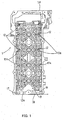
- FIG. 1 is a plan view of a cylinder head
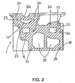
- FIG. 2 is an enlarged rear end view of FIG.1
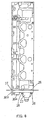
- FIG.3 is a right side view of FIG.1.
- FIG.4 is a plan view of the cylinder head on which an integrated unit of cover member and water outlet is mounted.
- FIG.5 and FIG.6 are an enlarged rear end view and a right side view of FIG.4 respectively.
- a cylinder head 1 is provided with two camshafts for intake and for exhaust (not shown) on the top, one of which camshafts has an extension for providing a fuel pump cam (not shown) made by extending the rear end opposite the timing sprocket (not shown).
- a sub-bearing portion 12a for supporting the extension is provided on the cylinder head 1. This sub-bearing portion 12a is formed as a unit on the top of the rear end wall of the cylinder head 1.
- the rear end wall of the cylinder head 1, which is a water outlet-mounting surface 19, is formed in parallel to the front-end wall 1a of the cylinder head 1,
- a cover member 30, which is to be mounted on the rear end wall as a separate unit, forms the sub-cam chamber 10.
- the cover member 30 is made previously together with a water outlet 22 as a unit and mounted on the water outlet-mounting surface 19 with bolts,
- water jacket openings 20, 20 In the rear end wall or water outlet surface 19 of the cylinder head 1 is formed water jacket openings 20, 20 to circulate the cooling water, to which the water outlet 22 is connected.
- the water outlet 22 is disposed in a separate position from the sub-cam chamber-forming portion 30a, and thereby it is prevented that the longitudinal length of the cylinder head 1 becomes too long.
- the water outlet 22 is formed integrally with the cover member 30.
- the cover member 30 is integrally composed of a sub-cam chamber- forming portion 30a that forms a sub-cam chamber 10 on the mounted condition and a core hole-closing portion 30b that is capable of closing the core-supporting holes 15, 15 of a valve case 9 (see FIG.5).
- the sub-cam chamber-forming portion 30a and core hole-closing portion 30b are made as a unit together with the water outlet 22,
- This core hole-closing portion 30b is formed in a flat plate with thickness less than the size of the sub-cam chamber forming portion 30a protruding from the rear end wall. Accordingly, the entire length of the cylinder head 1 is prevented from becoming larger size.
- a sub-bearing portion 12a On the top of the cylinder head 1 is formed a plurality of bearing portions 12, 12 in hollow fashion and on the top of the rear end wall, or the water outlet-mounting surface 19, is disposed a sub-bearing portion 12a. Under the sub-bearing portion 12a of the water outlet-mounting surface 19 is pierced through an oil return hole 23 to return the oil accumulated in the sub-cam chamber 10 into the valve case 9.
- each oil supply passage 17 is provided with a branch passage 17a facing on each bearing portion 12 or 12a.
- a plurality of mounting boltholes 24, 24 On the rear end wall are provided a plurality of mounting boltholes 24, 24.
- the integrated unit of cover member 30 and water outlet 22 is mounted on the rear end wall by tightening mounting bolts 28, 28 into the mounting boltholes 24, 24.
- a metal gasket 26 On the water outlet mounting surface 19 is placed a metal gasket 26 for sealing.
- liquid gasket 27 Also on the mated surfaces at the upper part, where chamfering is performed, is applied liquid gasket 27 for sealing.
- the sub-cam chamber-forming portion 30a of the cover member 30 can form the sub-cam chamber 10 on the outside of the rear end wall.
- the extension 3a of the camshaft 3 is disposed within this sub-cam chamber 10.
- the sub-cam chamber-forming portion 30a covers the extension 3a protruded outside from the cylinder head 1.
- the core hole-closing portion 30b of the cover member 30 closes the core-supporting holes 15, 15 used at the time of casting the valve case 9 and the rear ends of the oil passages 17, 17.
- the sub-bearing portion 12a for the extension 3a and the sub-cam bracket 2a are satisfactorily lubricated by oil that is sufficiently supplied through the oil passage 17. Besides, it is possible that the oil accumulated in the sub-cam chamber 10 is surely returned through an oil-returning hole 23 into the valve case 9 in the cylinder head 1, so that the oil is smoothly circulated.
- the separate cover member 30 is mounted on the rear end wall 19 of the cylinder head 1 favorably to form the sub-cam chamber 10. Further, the oil-returning hole 23 is formed through the cylinder head 1 so as to communicate with the inside of this sub-cam chamber 10, As a result, it is possible to surely return the oil through the oil-returning hole 23 into the cylinder head 1.
Abstract
Description
- The present invention relates to the structure of a cylinder head that constitutes an internal combustion engine for automobiles or for industrial machines.
- In a case of the prior art, as shown in the plan view of FIG.7. on a
cylinder head 1 are rotatably provided twocamshafts 3, 4 for intake and for exhaust respectively throughcam brackets camshafts 3, 4 are respectively providedtiming sprockets camshafts 3, 4 is provided with a plurality ofcams - The rear end of the
camshaft 3 on the left of the drawing has been extended rearward as an extension 3a, and accordingly the length of theleft camshaft 3 is longer than that of the right one 4. This extension 3a is provided with a fuel pump cam 7 for driving the fuel pump and also on the rear end of the extension 3a is mounted a camangle sensor plate 8 for detecting the cam angle. - In order to support the extension 3a of the
camshaft 3 there is provided asub-bearing portion 12a on thecylinder head 1. On thesub-bearing portion 12a is mounted a sub-cam bracket 2a with bolts to prevent bending of thecamshaft 3. - In the cylinder head structure as shown in FIG.7, the
cylinder head 1 is provided with asub-cam chamber 10 formed as a unit, which covers the rear part of the extension 3a of thecamshaft 3. In case of this cylinder head structure, thesub-cam chamber 10 is projected, so that manufacture of thecylinder head 1 becomes extremely difficult. - Accordingly, as disclosed in Jpn unexamined patent publication 2001-304063, for instance, there has been proposed a structure where the front and the rear end of a cylinder head are formed substantially in parallel and a separate fuel pump case is mounted on the cylinder head. In such a structure, however, there was a new problem that it is impossible that the oil within the sub-cam chamber is surely returned into the cylinder head.
- The present invention is worked out in view of the above-described problems in the prior art. It is an object of the present invention to provide a cylinder head that can surely return the oil within the sub-cam chamber provided outside the rear end wall into the inside of the cylinder head.
- The subject matter of the present invention is that in a cylinder head having the structure where two camshafts for intake and for exhaust are provided respectively on the top, one of which camshafts has an extension for providing a fuel pump cam made by extending the rear end opposite the timing sprocket, the front and the rear end wall are formed in parallel; the extension of the camshaft is disposed outside the rear end wall; a separate cover member is mounted on the outside of the rear end wall to form a sub-cam chamber for covering the extension; and an oil-returning hole is formed through the rear end wall so as to return the oil within the sub-cam chamber into the inside of the rear end wall.
- Accordingly, it is possible to obtain easy casting of the cylinder head and to favorably form a sub-cam chamber on the rear end wall of the cylinder head. Further, it is possible to surely return the oil within the sub-cam chamber through the oil-returning hole into the inside of the cylinder head. As a result, it is possible to satisfactorily lubricate the sub-bearing portion for supporting the extension of the camshaft and further to circulate the oil smoothly.
- In the drawings;
- FIG.1 is a plan view of a cylinder head;
- FIG.2 is an enlarged rear end view thereof;
- FIG.3 is a right side view thereof;
- FIG.4 is a plan view of the cylinder head on which and integrated unit of cover member and water outlet is mounted;
- FIG.5 is an enlarged rear end view of the cylinder head of FIG.4;
- FIG.6 is a right side view of the cylinder head of FIG.4; and
- FIG.7 is a plan view of a cylinder head provided with a camshaft having an extension in the prior art.
-
- Hereinafter, an embodiment of the present invention will be described with reference to the drawings.
- FIG. 1 is a plan view of a cylinder head, FIG. 2 is an enlarged rear end view of FIG.1, and FIG.3 is a right side view of FIG.1.
- Also, FIG.4 is a plan view of the cylinder head on which an integrated unit of cover member and water outlet is mounted. FIG.5 and FIG.6 are an enlarged rear end view and a right side view of FIG.4 respectively.
- Also in this embodiment, a
cylinder head 1 is provided with two camshafts for intake and for exhaust (not shown) on the top, one of which camshafts has an extension for providing a fuel pump cam (not shown) made by extending the rear end opposite the timing sprocket (not shown). Asub-bearing portion 12a for supporting the extension is provided on thecylinder head 1. Thissub-bearing portion 12a is formed as a unit on the top of the rear end wall of thecylinder head 1. The rear end wall of thecylinder head 1, which is a water outlet-mounting surface 19, is formed in parallel to the front-end wall 1a of thecylinder head 1, - In the
cylinder head 1 of this embodiment, acover member 30, which is to be mounted on the rear end wall as a separate unit, forms thesub-cam chamber 10. Thecover member 30 is made previously together with awater outlet 22 as a unit and mounted on the water outlet-mounting surface 19 with bolts, In the rear end wall orwater outlet surface 19 of thecylinder head 1 is formedwater jacket openings water outlet 22 is connected. Thewater outlet 22 is disposed in a separate position from the sub-cam chamber-formingportion 30a, and thereby it is prevented that the longitudinal length of thecylinder head 1 becomes too long. - Namely, the
water outlet 22 is formed integrally with thecover member 30. Thecover member 30 is integrally composed of a sub-cam chamber- formingportion 30a that forms asub-cam chamber 10 on the mounted condition and a core hole-closing portion 30b that is capable of closing the core-supportingholes portion 30a and core hole-closing portion 30b are made as a unit together with thewater outlet 22, This core hole-closing portion 30b is formed in a flat plate with thickness less than the size of the sub-camchamber forming portion 30a protruding from the rear end wall. Accordingly, the entire length of thecylinder head 1 is prevented from becoming larger size. - On the top of the
cylinder head 1 is formed a plurality of bearingportions mounting surface 19, is disposed asub-bearing portion 12a. Under thesub-bearing portion 12a of the water outlet-mounting surface 19 is pierced through anoil return hole 23 to return the oil accumulated in thesub-cam chamber 10 into the valve case 9. - Also, on the top of the
cylinder head 1 are formed a left and a rightoil supply passage portions oil supply passage 17 is provided with abranch passage 17a facing on each bearingportion - On the rear end wall are provided a plurality of mounting
boltholes cover member 30 andwater outlet 22 is mounted on the rear end wall by tighteningmounting bolts mounting boltholes outlet mounting surface 19 is placed ametal gasket 26 for sealing. Also on the mated surfaces at the upper part, where chamfering is performed, is appliedliquid gasket 27 for sealing. - Thus, by mounting the integrated unit of
cover member 30 andwater outlet 22 on the rear end wall of thecylinder head 1 with thebolt 28, the sub-cam chamber-formingportion 30a of thecover member 30 can form thesub-cam chamber 10 on the outside of the rear end wall. Within thissub-cam chamber 10 is disposed the extension 3a of thecamshaft 3. Namely, the sub-cam chamber-formingportion 30a covers the extension 3a protruded outside from thecylinder head 1. - Also, the core hole-
closing portion 30b of thecover member 30 closes the core-supportingholes oil passages - In this embodiment, the
sub-bearing portion 12a for the extension 3a and the sub-cam bracket 2a are satisfactorily lubricated by oil that is sufficiently supplied through theoil passage 17. Besides, it is possible that the oil accumulated in thesub-cam chamber 10 is surely returned through an oil-returninghole 23 into the valve case 9 in thecylinder head 1, so that the oil is smoothly circulated. - As described above in this embodiment, the
separate cover member 30 is mounted on therear end wall 19 of thecylinder head 1 favorably to form thesub-cam chamber 10. Further, the oil-returninghole 23 is formed through thecylinder head 1 so as to communicate with the inside of thissub-cam chamber 10, As a result, it is possible to surely return the oil through the oil-returninghole 23 into thecylinder head 1. - Having described the invention in detail and by reference to the preferred embodiment thereof, it will be apparent that other modifications and variations are possible without departing from the scope of the invention defined in the
Claims (8)
- A cylinder head having the structure where two camshafts for intake and exhaust are provided respectively on the top, one of which camshafts has an extension made by extending the rear end opposite the timing sprocket, comprising:the front and the rear end wall of said cylinder head formed in parallel;said extension disposed outside said rear end wall;a separate cover member mounted on the outside of said rear end wall to form a sub-cam chamber for covering said extension; andsaid rear end wall pierced by an oil-returning hole to return the oil within said sub-cam chamber into the inside of said rear end wall.
- A cylinder head as claimed in claim 1, wherein a sub-bearing portion to support said extension is provided on the rear part of said cylinder head.
- A cylinder head as claimed in claim 2, wherein said sub-bearing portion is provided on the top of said rear end wall.
- A cylinder head as claimed in claim 1, wherein said cover member comprises a sub-cam chamber-forming portion to form said sub-cam chamber and a core hole-closing portion to be capable of closing the core.supporting hole used at the time of casting said cylinder head, as a unit.
- A cylinder head as claimed in claim 4, wherein said core hole-closing portion is formed in a flat plate with thickness less than the size of said sub-cam chamber forming portion protruding from said rear end wall.
- A cylinder head as claimed in claim 1, wherein said cover member is integrated with a water outlet to be connected to the water jacket openings in said rear end wall.
- A cylinder head as claimed in claim 6, wherein said water outlet is disposed in a separate position from said sub-cam chamber forming portion.
- A cylinder head as claimed in claim 1, wherein said cover member is mounted on said rear end wall with bolts.
Applications Claiming Priority (2)
| Application Number | Priority Date | Filing Date | Title |
|---|---|---|---|
| JP2002066123A JP3721468B2 (en) | 2002-03-11 | 2002-03-11 | Cylinder head structure |
| JP2002066123 | 2002-03-11 |
Publications (3)
| Publication Number | Publication Date |
|---|---|
| EP1344927A2 true EP1344927A2 (en) | 2003-09-17 |
| EP1344927A3 EP1344927A3 (en) | 2003-12-10 |
| EP1344927B1 EP1344927B1 (en) | 2007-10-10 |
Family
ID=27764475
Family Applications (1)
| Application Number | Title | Priority Date | Filing Date |
|---|---|---|---|
| EP20030251474 Expired - Fee Related EP1344927B1 (en) | 2002-03-11 | 2003-03-10 | Cylinder head |
Country Status (3)
| Country | Link |
|---|---|
| EP (1) | EP1344927B1 (en) |
| JP (1) | JP3721468B2 (en) |
| DE (1) | DE60316740T2 (en) |
Cited By (1)
| Publication number | Priority date | Publication date | Assignee | Title |
|---|---|---|---|---|
| RU2507404C1 (en) * | 2012-06-26 | 2014-02-20 | Открытое акционерное общество "Автодизель" (Ярославский моторный завод) | Ice module, module housing and ice |
Families Citing this family (2)
| Publication number | Priority date | Publication date | Assignee | Title |
|---|---|---|---|---|
| JP4386112B2 (en) | 2007-07-20 | 2009-12-16 | トヨタ自動車株式会社 | engine |
| US8397689B2 (en) | 2010-05-17 | 2013-03-19 | GM Global Technology Operations LLC | Fuel pump tappet/roller follower lubrication |
Citations (1)
| Publication number | Priority date | Publication date | Assignee | Title |
|---|---|---|---|---|
| JP2001304063A (en) | 2000-04-27 | 2001-10-31 | Suzuki Motor Corp | Fuel pump installing structure of internal combustion engine |
Family Cites Families (3)
| Publication number | Priority date | Publication date | Assignee | Title |
|---|---|---|---|---|
| JPS59211754A (en) * | 1983-05-18 | 1984-11-30 | Honda Motor Co Ltd | Fuel pump driver device of internal-combustion engine |
| DE19650246A1 (en) * | 1996-12-04 | 1998-06-10 | Bosch Gmbh Robert | High-pressure fuel pump housed on engine wall |
| DE19701874C5 (en) * | 1997-01-21 | 2006-06-22 | Daimlerchrysler Ag | Camshaft bearing assembly in the cylinder head of an internal combustion engine |
-
2002
- 2002-03-11 JP JP2002066123A patent/JP3721468B2/en not_active Expired - Fee Related
-
2003
- 2003-03-10 DE DE2003616740 patent/DE60316740T2/en not_active Expired - Lifetime
- 2003-03-10 EP EP20030251474 patent/EP1344927B1/en not_active Expired - Fee Related
Patent Citations (1)
| Publication number | Priority date | Publication date | Assignee | Title |
|---|---|---|---|---|
| JP2001304063A (en) | 2000-04-27 | 2001-10-31 | Suzuki Motor Corp | Fuel pump installing structure of internal combustion engine |
Cited By (1)
| Publication number | Priority date | Publication date | Assignee | Title |
|---|---|---|---|---|
| RU2507404C1 (en) * | 2012-06-26 | 2014-02-20 | Открытое акционерное общество "Автодизель" (Ярославский моторный завод) | Ice module, module housing and ice |
Also Published As
| Publication number | Publication date |
|---|---|
| DE60316740D1 (en) | 2007-11-22 |
| JP3721468B2 (en) | 2005-11-30 |
| EP1344927B1 (en) | 2007-10-10 |
| DE60316740T2 (en) | 2008-07-24 |
| EP1344927A3 (en) | 2003-12-10 |
| JP2003269243A (en) | 2003-09-25 |
Similar Documents
| Publication | Publication Date | Title |
|---|---|---|
| US7717081B2 (en) | Engine cylinder head structure | |
| EP0374802B1 (en) | Camshaft driving arrangement for internal combustion engine | |
| EP1344927B1 (en) | Cylinder head | |
| JP2007321692A (en) | Cooling structure for internal combustion engine | |
| JP3695247B2 (en) | Four-cycle engine lubrication structure | |
| EP1394371A3 (en) | Oil pump arrangement in an oil sump | |
| US7121242B2 (en) | Lubricating structure of OHC internal combustion engine | |
| JPH0988539A (en) | Oil level gage installation structure | |
| US6948471B1 (en) | Engine lubricating system | |
| JP4529912B2 (en) | Lubricating oil supply device for internal combustion engine | |
| JP3146535B2 (en) | Lubricating oil passage for 4-stroke engine | |
| JP2009002219A (en) | V type ohv engine | |
| JP3235159B2 (en) | Lubrication system for V-type OHV engine | |
| US6935298B2 (en) | Lubricating device for motorcycle engine | |
| JP3821342B2 (en) | Oil passage structure of internal combustion engine | |
| JP2005113731A (en) | Lubricating device for camshaft | |
| JPS63201308A (en) | Diesel engine | |
| JP4246130B2 (en) | Oil passage arrangement structure of internal combustion engine | |
| JP4437908B2 (en) | Engine oil return structure | |
| JPS581610Y2 (en) | Overhead valve engine lubrication system | |
| JP2630820B2 (en) | Cam bearing lubrication system for DOHC engine | |
| JP2516488Y2 (en) | DOHC engine silida head | |
| JPH0536971Y2 (en) | ||
| JP2516637Y2 (en) | DOHC engine cylinder head | |
| JP3131018B2 (en) | Structure of cylinder head in slant type internal combustion engine |
Legal Events
| Date | Code | Title | Description |
|---|---|---|---|
| PUAI | Public reference made under article 153(3) epc to a published international application that has entered the european phase |
Free format text: ORIGINAL CODE: 0009012 |
|
| AK | Designated contracting states |
Kind code of ref document: A2 Designated state(s): AT BE BG CH CY CZ DE DK EE ES FI FR GB GR HU IE IT LI LU MC NL PT RO SE SI SK TR |
|
| AX | Request for extension of the european patent |
Extension state: AL LT LV MK |
|
| PUAL | Search report despatched |
Free format text: ORIGINAL CODE: 0009013 |
|
| AK | Designated contracting states |
Kind code of ref document: A3 Designated state(s): AT BE BG CH CY CZ DE DK EE ES FI FR GB GR HU IE IT LI LU MC NL PT RO SE SI SK TR |
|
| AX | Request for extension of the european patent |
Extension state: AL LT LV MK |
|
| RIC1 | Information provided on ipc code assigned before grant |
Ipc: 7F 02F 1/24 B Ipc: 7F 02F 7/00 B Ipc: 7F 02F 1/42 A Ipc: 7F 02M 37/06 B Ipc: 7F 02B 67/04 B Ipc: 7F 02M 39/02 B |
|
| 17P | Request for examination filed |
Effective date: 20040311 |
|
| AKX | Designation fees paid |
Designated state(s): DE FR GB |
|
| 17Q | First examination report despatched |
Effective date: 20061208 |
|
| GRAP | Despatch of communication of intention to grant a patent |
Free format text: ORIGINAL CODE: EPIDOSNIGR1 |
|
| GRAS | Grant fee paid |
Free format text: ORIGINAL CODE: EPIDOSNIGR3 |
|
| GRAA | (expected) grant |
Free format text: ORIGINAL CODE: 0009210 |
|
| AK | Designated contracting states |
Kind code of ref document: B1 Designated state(s): DE FR GB |
|
| REG | Reference to a national code |
Ref country code: GB Ref legal event code: FG4D |
|
| REF | Corresponds to: |
Ref document number: 60316740 Country of ref document: DE Date of ref document: 20071122 Kind code of ref document: P |
|
| ET | Fr: translation filed | ||
| PLBE | No opposition filed within time limit |
Free format text: ORIGINAL CODE: 0009261 |
|
| STAA | Information on the status of an ep patent application or granted ep patent |
Free format text: STATUS: NO OPPOSITION FILED WITHIN TIME LIMIT |
|
| 26N | No opposition filed |
Effective date: 20080711 |
|
| PGFP | Annual fee paid to national office [announced via postgrant information from national office to epo] |
Ref country code: DE Payment date: 20130306 Year of fee payment: 11 Ref country code: GB Payment date: 20130306 Year of fee payment: 11 Ref country code: FR Payment date: 20130325 Year of fee payment: 11 |
|
| REG | Reference to a national code |
Ref country code: DE Ref legal event code: R119 Ref document number: 60316740 Country of ref document: DE |
|
| GBPC | Gb: european patent ceased through non-payment of renewal fee |
Effective date: 20140310 |
|
| REG | Reference to a national code |
Ref country code: FR Ref legal event code: ST Effective date: 20141128 |
|
| REG | Reference to a national code |
Ref country code: DE Ref legal event code: R119 Ref document number: 60316740 Country of ref document: DE Effective date: 20141001 |
|
| PG25 | Lapsed in a contracting state [announced via postgrant information from national office to epo] |
Ref country code: DE Free format text: LAPSE BECAUSE OF NON-PAYMENT OF DUE FEES Effective date: 20141001 Ref country code: GB Free format text: LAPSE BECAUSE OF NON-PAYMENT OF DUE FEES Effective date: 20140310 Ref country code: FR Free format text: LAPSE BECAUSE OF NON-PAYMENT OF DUE FEES Effective date: 20140331 |