EP1344913A2 - Verfahren und Vorrichtung zur Regelung des Kühlmittelvolumens in einer Brennkraftmaschine - Google Patents
Verfahren und Vorrichtung zur Regelung des Kühlmittelvolumens in einer Brennkraftmaschine Download PDFInfo
- Publication number
- EP1344913A2 EP1344913A2 EP03100364A EP03100364A EP1344913A2 EP 1344913 A2 EP1344913 A2 EP 1344913A2 EP 03100364 A EP03100364 A EP 03100364A EP 03100364 A EP03100364 A EP 03100364A EP 1344913 A2 EP1344913 A2 EP 1344913A2
- Authority
- EP
- European Patent Office
- Prior art keywords
- coolant
- internal combustion
- combustion engine
- pump
- temperature
- Prior art date
- Legal status (The legal status is an assumption and is not a legal conclusion. Google has not performed a legal analysis and makes no representation as to the accuracy of the status listed.)
- Withdrawn
Links
Images

Classifications
-
- F—MECHANICAL ENGINEERING; LIGHTING; HEATING; WEAPONS; BLASTING
- F01—MACHINES OR ENGINES IN GENERAL; ENGINE PLANTS IN GENERAL; STEAM ENGINES
- F01P—COOLING OF MACHINES OR ENGINES IN GENERAL; COOLING OF INTERNAL-COMBUSTION ENGINES
- F01P5/00—Pumping cooling-air or liquid coolants
- F01P5/10—Pumping liquid coolant; Arrangements of coolant pumps
-
- F—MECHANICAL ENGINEERING; LIGHTING; HEATING; WEAPONS; BLASTING
- F01—MACHINES OR ENGINES IN GENERAL; ENGINE PLANTS IN GENERAL; STEAM ENGINES
- F01P—COOLING OF MACHINES OR ENGINES IN GENERAL; COOLING OF INTERNAL-COMBUSTION ENGINES
- F01P7/00—Controlling of coolant flow
- F01P7/14—Controlling of coolant flow the coolant being liquid
- F01P7/16—Controlling of coolant flow the coolant being liquid by thermostatic control
- F01P7/164—Controlling of coolant flow the coolant being liquid by thermostatic control by varying pump speed
-
- F—MECHANICAL ENGINEERING; LIGHTING; HEATING; WEAPONS; BLASTING
- F01—MACHINES OR ENGINES IN GENERAL; ENGINE PLANTS IN GENERAL; STEAM ENGINES
- F01P—COOLING OF MACHINES OR ENGINES IN GENERAL; COOLING OF INTERNAL-COMBUSTION ENGINES
- F01P5/00—Pumping cooling-air or liquid coolants
- F01P5/10—Pumping liquid coolant; Arrangements of coolant pumps
- F01P5/12—Pump-driving arrangements
- F01P2005/125—Driving auxiliary pumps electrically
-
- F—MECHANICAL ENGINEERING; LIGHTING; HEATING; WEAPONS; BLASTING
- F01—MACHINES OR ENGINES IN GENERAL; ENGINE PLANTS IN GENERAL; STEAM ENGINES
- F01P—COOLING OF MACHINES OR ENGINES IN GENERAL; COOLING OF INTERNAL-COMBUSTION ENGINES
- F01P7/00—Controlling of coolant flow
- F01P7/14—Controlling of coolant flow the coolant being liquid
- F01P2007/146—Controlling of coolant flow the coolant being liquid using valves
-
- F—MECHANICAL ENGINEERING; LIGHTING; HEATING; WEAPONS; BLASTING
- F01—MACHINES OR ENGINES IN GENERAL; ENGINE PLANTS IN GENERAL; STEAM ENGINES
- F01P—COOLING OF MACHINES OR ENGINES IN GENERAL; COOLING OF INTERNAL-COMBUSTION ENGINES
- F01P2023/00—Signal processing; Details thereof
-
- F—MECHANICAL ENGINEERING; LIGHTING; HEATING; WEAPONS; BLASTING
- F01—MACHINES OR ENGINES IN GENERAL; ENGINE PLANTS IN GENERAL; STEAM ENGINES
- F01P—COOLING OF MACHINES OR ENGINES IN GENERAL; COOLING OF INTERNAL-COMBUSTION ENGINES
- F01P2025/00—Measuring
- F01P2025/08—Temperature
- F01P2025/32—Engine outcoming fluid temperature
-
- F—MECHANICAL ENGINEERING; LIGHTING; HEATING; WEAPONS; BLASTING
- F01—MACHINES OR ENGINES IN GENERAL; ENGINE PLANTS IN GENERAL; STEAM ENGINES
- F01P—COOLING OF MACHINES OR ENGINES IN GENERAL; COOLING OF INTERNAL-COMBUSTION ENGINES
- F01P2037/00—Controlling
- F01P2037/02—Controlling starting
-
- F—MECHANICAL ENGINEERING; LIGHTING; HEATING; WEAPONS; BLASTING
- F01—MACHINES OR ENGINES IN GENERAL; ENGINE PLANTS IN GENERAL; STEAM ENGINES
- F01P—COOLING OF MACHINES OR ENGINES IN GENERAL; COOLING OF INTERNAL-COMBUSTION ENGINES
- F01P7/00—Controlling of coolant flow
- F01P7/02—Controlling of coolant flow the coolant being cooling-air
- F01P7/08—Controlling of coolant flow the coolant being cooling-air by cutting in or out of pumps
-
- F—MECHANICAL ENGINEERING; LIGHTING; HEATING; WEAPONS; BLASTING
- F01—MACHINES OR ENGINES IN GENERAL; ENGINE PLANTS IN GENERAL; STEAM ENGINES
- F01P—COOLING OF MACHINES OR ENGINES IN GENERAL; COOLING OF INTERNAL-COMBUSTION ENGINES
- F01P7/00—Controlling of coolant flow
- F01P7/14—Controlling of coolant flow the coolant being liquid
- F01P7/16—Controlling of coolant flow the coolant being liquid by thermostatic control
- F01P7/167—Controlling of coolant flow the coolant being liquid by thermostatic control by adjusting the pre-set temperature according to engine parameters, e.g. engine load, engine speed
Definitions
- the invention relates to a method and an apparatus for Regulation of the coolant volume flow in an internal combustion engine according to the preambles of claims 1 and 14.
- Such conventional cooling systems usually include one either directly or indirectly via a mobile Traction means, e.g. V-belt driven by the internal combustion engine Coolant pump and an expansion thermostat.
- the coolant pump therefore works and depends on the engine speed designed so that in any operating state of the internal combustion engine sufficient coolant flow is provided becomes.
- the coolant temperature is regulated. This is a temperature dependent Expansion regulator provided a valve actuated, the increasing with decreasing coolant temperature Coolant flow past the radiator. Dehnstoffregler and valve form a structural unit and are in general referred to as a radiator thermostat.
- the radiator thermostat Starting from the cold operating state of the internal combustion engine the radiator thermostat is initially closed and the coolant circulation takes place exclusively in a bypass circuit the internal combustion engine instead. This is also called “smaller Cooling circuit ". From a certain coolant temperature opens the radiator thermostat and the coolant flow flows to the radiator, there due to the wind and / or the radiator fan cooled and back to Internal combustion engine returned. This is also called “great Cooling circuit ".
- Rapid heating of such a liquid-cooled Internal combustion engine can also be achieved in that the circulation of the coolant in the "small cooling circuit" (Bypass) is interrupted. This can be done, for example, by a suitable coolant mixing valve or mechanically from the internal combustion engine driven coolant pump Providing a switchable clutch can be achieved.
- the cooling circuit can be switched off easily of the electric motor of the coolant pump is interrupted become. Since the coolant no longer circulates, one also speaks of a "standing coolant".
- coolant temperature sensors usually are arranged outside the internal combustion engine and as a result no more reliable signals via the thermal Deliver the operating state of the internal combustion engine.
- Another one Problem is that after activating the coolant circulation relatively cold coolant in the internal combustion engine flows in, which in the worst case is a thermal shock and result in component damage can.
- the problem can be solved, for example, by depending on an initial coolant temperature only for the circulation of the coolant is prevented for a certain period of time becomes. In this procedure, however, one must be sufficient large safety margin regarding the critical temperature for the internal combustion engine, so that a Part of the potential for shortening the heating-up time is not used remains.
- the invention has for its object a method and a device for regulating the coolant volume flow in specify an internal combustion engine, with which or with one rapid and even heating of the internal combustion engine is ensured.
- Coolant pump operating in a selected operating area the internal combustion engine via signals from a control device is controlled such that between the coolant inlet and coolant outlet of the internal combustion engine located coolant volume alternately from the internal combustion engine is pumped out and in, a rapid and even heating of the internal combustion engine be ensured. This is especially true during a cold start and important when warming up the internal combustion engine.
- a temperature sensor at the coolant outlet can be used here the thermal condition of the internal combustion engine was assessed very precisely become.
- Another benefit is that heated coolant pumped back into the internal combustion engine after leaving it and thus hardly any heat is lost.
- Another advantage is that the Internal combustion engine, i.e. at the coolant inlet and at the coolant outlet a more moderate temperature gradient is achieved and thus after activation of the continuous circulation the risk of thermal shock is significantly reduced.
- the method can be carried out particularly easily if an electrically driven, in terms of their pumping direction reversible coolant pump is used.
- the reversal the pumping direction can be done in a simple manner by appropriate electrical control signals from a control device respectively.
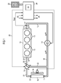
- the coolant circuit of the internal combustion engine 10 has one Reversible coolant pump 11, which in the shown embodiment as an electrically driven Coolant pump is designed. In particular, for example also a radial pump with adjustable speed be used.
- an electrically controllable actuator 12 in the form a 3/2 way proportional valve.
- This actuator has three connections I, II, III, in the following the connections I and II also as inputs and the Connection III can also be called an output.
- By appropriate Control of the actuator 12 can Coolant volume flow depending on the operating range of the internal combustion engine Divide 10 as explained in more detail later becomes.
- the internal combustion engine 10 has one, not shown Cooling jacket around the cylinder 13 and the coolant pump 11 conveys the coolant into the cooling jacket around the cylinders 13, it flushes them and reaches the cylinder head through through holes.
- a Coolant outlet 14 is provided, to which a line 15 is connected is.
- the line 15 leads to an unspecified Connection of the coolant pump 11.
- the other Connection of the coolant pump 11 leads via a line 16 a coolant inlet 17 of a cooler 18.
- the cooler 18 the waste heat generated in the internal combustion engine 10 the coolant is discharged to the environment.
- at least one is also electrical driven fan 19 is provided. Switching on the fan 19 is usually temperature controlled or regulated.
- a coolant outlet 20 of the cooler 18 is via a line 21 connected to the input I of the actuator 12.
- the Line 16 which connects the coolant pump 11 to the coolant inlet 17 connects to the cooler 18 is a branch for one Bypass line 22 provided to the input II of the actuator 12 leads.
- the output III of the actuator 12 is over a line 23 with an engine-side coolant inlet 24 connected.
- the actuator 12 signals via a control line 25 connected to a control device 26.
- Such electronic control devices that usually one or more microprocessors, as well as a time counter 29 include and that in addition to fuel injection a variety of other control and regulatory tasks of the Take over internal combustion engine 10 are known per se, so that only in the following in connection with the invention relevant structure and how it works becomes.
- a temperature sensor 27 on the engine-side coolant outlet 14 provides the temperature of the coolant on the engine Exit corresponding signal TKW to the control device 26 for controlling actuator 12 as required.
- the control device 26 are also a variety of means corresponding input signals recorded in corresponding sensors referred to the figures with the reference symbol ES.
- the individual actuators and components are output signals AS controlled that to operate the internal combustion engine 10 are necessary.
- the electric coolant pump 11 and the fan 19 are also via control lines with the control device 26 connected.
- control device 26 has a memory 28 connected, in which, among other things, predetermined threshold values SW1, SW2 stored for the temperature of the coolant are.
- the signal TKW of the temperature sensor 27 is read in at the start of the internal combustion engine 10 and compared with a predetermined threshold value SW1, which characterizes a cold internal combustion engine and is stored in the memory 28. If the value of the coolant temperature is below this threshold value SW1, a cold start of the internal combustion engine is concluded and the actuator 12 is controlled by an electrical signal from the control device 26 such that there is a flow connection between the input II and the output III of the actuator 12.
- the coolant pump 11 is then briefly actuated for a period T before such that a coolant volume flow flows via the line 16, the bypass line 22, the control valve 12, the line 23 to the location of the temperature sensor 27.
- the direction of the coolant volume flow is shown in FIG. 1 with solid arrow symbols.
- the time period T before during which the coolant pump 11 is activated so that a coolant flow takes place to the location of the temperature sensor 27, is determined experimentally for the internal combustion engine 10 in question. It is essentially dependent on the structural design of the internal combustion engine, in particular on the mass, the number of cylinders and the dimensioning of the cooling jacket. This time period T before is monitored by the time counter 29 of the control device 26 and is usually in the range of seconds.
- the coolant pump 11 is deactivated again.
- the signal from the temperature sensor 27 is continuously read in and compared with a further threshold value SW2, which characterizes a warm internal combustion engine. Typical values for this are in the range of 80 ° C - 90 ° C. This value is also stored in the memory 28.
- the coolant pump 11 is reactivated after a further period of time T wait , which is also determined experimentally. However, the coolant pump is now controlled in such a way that the coolant is now delivered in the opposite direction by the internal combustion engine 10.
- the direction of the coolant volume flow is shown in FIG. 1 with arrow symbols shown in broken lines.
- the time period Tschreib during which the coolant pump 11 pumps the coolant 11 in the opposite direction is preferably identical to the above-mentioned time period T before .
- the coolant pump 11 is now controlled so that a continuous Coolant flow in one direction from the coolant pump 11, via line 16, the Radiator 18, line 21, actuator 12 and line 23 to the internal combustion engine 10 and from there again via the Line 15 can circulate back to the coolant pump 11.
- the bypass line 22 is switched off, i.e. it there is no connection between input II and the output III of the actuator 12.
- the direction of the coolant volume flow is again drawn in with arrow symbols in FIG.
- the invention was explained using an example in which the Reversal of the pump direction of the coolant pump takes place electrically.
- a coolant pump mechanically driven by the internal combustion engine possible.
- mechanical components such as ensuring gears and clutches, that the coolant pump from both the engine temporarily disconnected, as well as the pump direction changed can be.
Landscapes
- Engineering & Computer Science (AREA)
- Chemical & Material Sciences (AREA)
- Combustion & Propulsion (AREA)
- Mechanical Engineering (AREA)
- General Engineering & Computer Science (AREA)
- Combined Controls Of Internal Combustion Engines (AREA)
- Lubrication Of Internal Combustion Engines (AREA)
Abstract
Description
- Fig. 1
- in schematischer Darstellung einen Kühlmittelkreislauf einer Brennkraftmaschine beim Kaltstart und
- Fig. 2
- in schematischer Darstellung einen Kühlmittelkreislauf bei betriebswarmer Brennkraftmaschine.
Claims (16)
- Verfahren zur Regelung des Kühlmittelvolumenstromes innerhalb eines Kühlmittelkreislaufes einer Brennkraftmaschine (10) mit einer Kühlmittelpumpe (11), welche das Kühlmittel umwälzt, wobei mittels eines elektrisch ansteuerbaren Stellgliedes (12) abhängig von einer, die Temperatur der Brennkraftmaschine (10) charakterisierenden Größe der Kühlmittelvolumenstrom von einem, einen Kühlmitteleinlass (24) und einen Kühlmittelauslass (14) der Brennkraftmaschine (10) verbindenden Bypass (22) zu einer durch einen Kühler (18) der Brennkraftmaschine (10) führenden Kühlmittelkreislauf umgeschaltet wird,
dadurch gekennzeichnet, dassals Kühlmittelpumpe (11) eine bezüglich ihrer Pumprichtung umkehrbare Kühlmittelpumpe verwendet wird,in einem ausgewählten Betriebsbereich der Brennkraftmaschine (10) die Kühlmittelpumpe (11) derart angesteuert wird, dass das zwischen Kühlmitteleinlass (24) und Kühlmittelauslass (14) befindliche Kühlmittelvolumen alternierend aus der Brennkraftmaschine (10) heraus- und hineingepumpt wird. - Verfahren nach Anspruch 1, dadurch gekennzeichnet, dass der alternierende Betrieb der Kühlmittelpumpe (11) beendet wird, wenn die die Temperatur der Brennkraftmaschine (10) charakterisierende Größe einen vorgegebenen Schwellenwert (SW2) erreicht hat.
- Verfahren nach Anspruch 2, dadurch gekennzeichnet, dass als die die Temperatur der Brennkraftmaschine (10) charakterisierende Größe die Temperatur (TKW) des Kühlmittels herangezogen wird.
- Verfahren nach Anspruch 3, dadurch gekennzeichnet, dass die Temperatur (TKW) des Kühlmittels an dem Kühlmittelauslass (14) mittels eines Temperatursensors (27) erfasst wird.
- Verfahren nach Anspruch 1, dadurch gekennzeichnet, dass die Zeitdauern (Tvor, Trück) während derer die Kühlmittelpumpe (11) in der einen und der anderen Richtung aktiviert wird, identisch sind.
- Verfahren nach Anspruch 1, dadurch gekennzeichnet, dass das Umschalten zwischen den beiden Pumprichtungen erst nach Ablauf einer vorgegebenen Zeitdauer (Twait) erfolgt.
- Verfahren nach Anspruch 5 und 6, dadurch gekennzeichnet, dass die Zeitdauern (Tvor, Trück, Twait) experimentell abhängig von der konstruktiven Ausgestaltung der Brennkraftmaschine (10) ermittelt werden.
- Verfahren nach Anspruch 1, dadurch gekennzeichnet, dass der Betriebsbereich der Kaltstart der Brennkraftmaschine (10) ist.
- Verfahren nach Anspruch 1, dadurch gekennzeichnet, dass der Betriebsbereich der Warmlauf der Brennkraftmaschine (10) ist.
- Verfahren nach Anspruch 1, dadurch gekennzeichnet, dass eine elektrisch angetriebene Kühlmittelpumpe (11) verwendet wird.
- Verfahren nach Anspruch 1, dadurch gekennzeichnet, dass eine mechanisch von der Brennkraftmaschine (10) angetriebene Kühlmittelpumpe (11) verwendet wird.
- Verfahren nach Anspruch 2, dadurch gekennzeichnet, dass bei Erreichen des Schwellenwertes (SW2) die Kühlmittelpumpe (11) derart angesteuert wird, dass der Kühlmittelvolumenstrom kontinuierlich in einer Richtung gepumpt wird.
- Verfahren nach Anspruch 1 und 12, dadurch gekennzeichnet, dass bei Erreichen des Schwellenwertes (SW2) der Kühlmittelvolumenstrom über den Kühler (18) geleitet wird.
- Vorrichtung zur Regelung des Kühlmittelvolumenstromes innerhalb eines Kühlmittelkreislaufes einer Brennkraftmaschine (10)gekennzeichnet, durchmit einer Kühlmittelpumpe (11), welche das Kühlmittel umwälzt,mit einem elektrisch ansteuerbaren Stellglied (12), das abhängig von einer, die Temperatur der Brennkraftmaschine (10) charakterisierenden Größe den Kühlmittelvolumenstrom von einem, einen Kühlmitteleinlass (24) und einen Kühlmittelauslass (14) der Brennkraftmaschine (10) verbindenden Bypass (22) zu einer durch einen Kühler (18) der Brennkraftmaschine (10) führenden Kühlmittelkreislauf umschaltet,eine bezüglich ihrer Pumprichtung umkehrbare Kühlmittelpumpe (11),durch eine Steuerungseinrichtung (26), welche in einem ausgewählten Betriebsbereich der Brennkraftmaschine (10) die Kühlmittelpumpe (11) derart ansteuert, dass das zwischen Kühlmitteleinlass (24) und Kühlmittelauslass (14) befindliche Kühlmittelvolumen alternierend aus der Brennkraftmaschine (10) heraus- und hineingepumpt wird.
- Vorrichtung nach Anspruch 14, dadurch gekennzeichnet, dass das Stellglied (12) als ein elektrisch ansteuerbares 3/2 Wege-Proportionalventil ausgestaltet ist.
- Vorrichtung nach Anspruch 14, dadurch gekennzeichnet, dass am Kühlmittelauslass (14) der Brennkraftmaschine (10) ein Temperatursensor (27) vorgesehen ist, dessen Signal (TKW) zur Steuerung des Stellgliedes (12) und der Kühlmittelpumpe (11) herangezogen wird.
Applications Claiming Priority (2)
| Application Number | Priority Date | Filing Date | Title |
|---|---|---|---|
| DE2002111060 DE10211060B4 (de) | 2002-03-13 | 2002-03-13 | Verfahren und Vorrichtung zur Regelung des Kühlmittelvolumenstromes in einer Brennkraftmaschine |
| DE10211060 | 2002-03-13 |
Publications (2)
| Publication Number | Publication Date |
|---|---|
| EP1344913A2 true EP1344913A2 (de) | 2003-09-17 |
| EP1344913A3 EP1344913A3 (de) | 2005-03-16 |
Family
ID=27762899
Family Applications (1)
| Application Number | Title | Priority Date | Filing Date |
|---|---|---|---|
| EP03100364A Withdrawn EP1344913A3 (de) | 2002-03-13 | 2003-02-17 | Verfahren und Vorrichtung zur Regelung des Kühlmittelvolumens in einer Brennkraftmaschine |
Country Status (2)
| Country | Link |
|---|---|
| EP (1) | EP1344913A3 (de) |
| DE (1) | DE10211060B4 (de) |
Cited By (1)
| Publication number | Priority date | Publication date | Assignee | Title |
|---|---|---|---|---|
| ITMI20110827A1 (it) * | 2011-05-12 | 2012-11-13 | O M P Officine Mazzocco Pagnoni S R L | Pompa idraulica per il raffreddamento di un motore a combustione interna |
Families Citing this family (1)
| Publication number | Priority date | Publication date | Assignee | Title |
|---|---|---|---|---|
| DE102020127420A1 (de) | 2020-10-19 | 2022-04-21 | Bayerische Motoren Werke Aktiengesellschaft | Verfahren zum Betreiben eines Kühlkreislaufs sowie Kraftfahrzeug |
Citations (1)
| Publication number | Priority date | Publication date | Assignee | Title |
|---|---|---|---|---|
| DE3238919A1 (de) | 1981-10-29 | 1983-05-11 | Niels Thure 5260 Odense Hallin | Verfahren zum betrieb einer fluessigkeitsgekuehlten verbrennungskraftmaschine, sowie eine vorrichtung zur durchfuehrung des verfahrens |
Family Cites Families (7)
| Publication number | Priority date | Publication date | Assignee | Title |
|---|---|---|---|---|
| US2976698A (en) * | 1951-09-19 | 1961-03-28 | Muffly Glenn | Reversible refrigerating systems |
| JP2712711B2 (ja) * | 1990-02-16 | 1998-02-16 | 株式会社デンソー | 内燃機関の冷却方法及びその装置 |
| DE4307841C1 (de) * | 1993-03-12 | 1994-01-27 | Webasto Thermosysteme Gmbh | Heizkreislauf-System eines Fahrzeuges |
| US6178928B1 (en) * | 1998-06-17 | 2001-01-30 | Siemens Canada Limited | Internal combustion engine total cooling control system |
| US5950576A (en) * | 1998-06-30 | 1999-09-14 | Siemens Canada Limited | Proportional coolant valve |
| DE19925986A1 (de) * | 1999-06-08 | 2000-12-14 | Bosch Gmbh Robert | Kühlkreislauf zum Kühlen eines Verbrennungsmotors |
| DE19948890A1 (de) * | 1999-10-11 | 2001-04-19 | Reinz Dichtungs Gmbh | Oszillierender Kühlwasserkeislauf |
-
2002
- 2002-03-13 DE DE2002111060 patent/DE10211060B4/de not_active Expired - Fee Related
-
2003
- 2003-02-17 EP EP03100364A patent/EP1344913A3/de not_active Withdrawn
Patent Citations (1)
| Publication number | Priority date | Publication date | Assignee | Title |
|---|---|---|---|---|
| DE3238919A1 (de) | 1981-10-29 | 1983-05-11 | Niels Thure 5260 Odense Hallin | Verfahren zum betrieb einer fluessigkeitsgekuehlten verbrennungskraftmaschine, sowie eine vorrichtung zur durchfuehrung des verfahrens |
Cited By (1)
| Publication number | Priority date | Publication date | Assignee | Title |
|---|---|---|---|---|
| ITMI20110827A1 (it) * | 2011-05-12 | 2012-11-13 | O M P Officine Mazzocco Pagnoni S R L | Pompa idraulica per il raffreddamento di un motore a combustione interna |
Also Published As
| Publication number | Publication date |
|---|---|
| EP1344913A3 (de) | 2005-03-16 |
| DE10211060B4 (de) | 2005-03-17 |
| DE10211060A1 (de) | 2003-10-09 |
Similar Documents
| Publication | Publication Date | Title |
|---|---|---|
| EP1947308B1 (de) | Integriertes Motorkühlsystem | |
| DE102004034443B4 (de) | Kühlsystem für einen Verbrennungsmotor und Verfahren zum Steuern eines solchen Kühlsystems | |
| DE102017207159B4 (de) | Antriebsstrang-wärmemanagementsystem | |
| DE102011119587A1 (de) | Verfahren zum steuern von abgaswärmerückgewinnungssystemen in fahrzeugen | |
| DE102013103423A1 (de) | Verbrennungsmotor-Kühlsystem für ein Fahrzeug und Steuerungsverfahren desselben | |
| DE102014201717A1 (de) | Brennkraftmaschine mit flüssigkeitsgekühltem Zylinderkopf und Zylinderblock und Verfahren zur Steuerung der Kühlung einer derartigen Brennkraftmaschine | |
| DE3433319A1 (de) | Einkreiskuehlung fuer ladeluftgekuehlte schiffsmotoren | |
| DE10226904B4 (de) | Motorkühlsystem eines Kraftfahrzeuges | |
| EP0593928B1 (de) | Wärmespeichersystem für den Kaltstart von Verbrennungsmaschinen | |
| DE102012202600A1 (de) | System and method for controlling a temperature of oil in a power-plant of a vehicle | |
| DE10319762A1 (de) | Kreislauf zur Kühlung von Ladeluft und Verfahren zum Betreiben eines derartigen Kreislaufs | |
| DE3125709A1 (de) | Heizvorrichtung fuer den fahrgastraum eines kraftfahrzeuges | |
| DE102008048373A1 (de) | Motorkühlsystem mit Kühlmittelabsperrvorrichtung | |
| WO2003106825A1 (de) | Verfahren zum betrieb einer flüssigkeitsgekühlten brennkraftmaschine | |
| DE102017221915A1 (de) | Getrennte Kühleinrichtung und ein getrenntes Kühlsystem für ein Fahrzeug | |
| DE102021101029B4 (de) | Thermisches System zum Regeln einer Fluidtemperatur | |
| WO2006066713A1 (de) | System und verfahren zum temperieren eines motoröls einer brennkraftmaschine eines kraftfahrzeugs | |
| DE112014004338B4 (de) | Kühlsystem in einem Fahrzeug | |
| DE4432292B4 (de) | Verteilereinrichtung für das Kühl- bzw. Heizsystem von Fahrzeugen mit Verbrennungsmotoren | |
| DE102009001129B4 (de) | Kühlstrategie für Verbrennungsmotoren | |
| EP1220976B1 (de) | Oszillierender kühlwasserkreislauf | |
| DE10211060B4 (de) | Verfahren und Vorrichtung zur Regelung des Kühlmittelvolumenstromes in einer Brennkraftmaschine | |
| DE19516406A1 (de) | Anordnung mit einem Verbrennungsmotor | |
| DE102004030153A1 (de) | Kühlkreislauf für eine Brennkraftmaschine | |
| DE102013203476A1 (de) | Brennkraftmaschine mit flüssigkeitsgekühltem Zylinderkopf und flüssigkeitsgekühltem Zylinderblock und Verfahren zur Steuerung der Kühlung einer derartigen Brennkraftmaschine |
Legal Events
| Date | Code | Title | Description |
|---|---|---|---|
| PUAI | Public reference made under article 153(3) epc to a published international application that has entered the european phase |
Free format text: ORIGINAL CODE: 0009012 |
|
| AK | Designated contracting states |
Kind code of ref document: A2 Designated state(s): AT BE BG CH CY CZ DE DK EE ES FI FR GB GR HU IE IT LI LU MC NL PT SE SI SK TR |
|
| AX | Request for extension of the european patent |
Extension state: AL LT LV MK RO |
|
| PUAL | Search report despatched |
Free format text: ORIGINAL CODE: 0009013 |
|
| AK | Designated contracting states |
Kind code of ref document: A3 Designated state(s): AT BE BG CH CY CZ DE DK EE ES FI FR GB GR HU IE IT LI LU MC NL PT SE SI SK TR |
|
| AX | Request for extension of the european patent |
Extension state: AL LT LV MK RO |
|
| 17P | Request for examination filed |
Effective date: 20050422 |
|
| AKX | Designation fees paid |
Designated state(s): DE FR GB IT |
|
| RAP1 | Party data changed (applicant data changed or rights of an application transferred) |
Owner name: CONTINENTAL AUTOMOTIVE GMBH |
|
| 17Q | First examination report despatched |
Effective date: 20100210 |
|
| STAA | Information on the status of an ep patent application or granted ep patent |
Free format text: STATUS: THE APPLICATION IS DEEMED TO BE WITHDRAWN |
|
| 18D | Application deemed to be withdrawn |
Effective date: 20100622 |