EP1344867A2 - Lighting fixture flush mounted in the ground - Google Patents
Lighting fixture flush mounted in the ground Download PDFInfo
- Publication number
- EP1344867A2 EP1344867A2 EP03003334A EP03003334A EP1344867A2 EP 1344867 A2 EP1344867 A2 EP 1344867A2 EP 03003334 A EP03003334 A EP 03003334A EP 03003334 A EP03003334 A EP 03003334A EP 1344867 A2 EP1344867 A2 EP 1344867A2
- Authority
- EP
- European Patent Office
- Prior art keywords
- light
- underfloor
- prism
- horizontal
- housing
- Prior art date
- Legal status (The legal status is an assumption and is not a legal conclusion. Google has not performed a legal analysis and makes no representation as to the accuracy of the status listed.)
- Withdrawn
Links
Images


Classifications
-
- B—PERFORMING OPERATIONS; TRANSPORTING
- B64—AIRCRAFT; AVIATION; COSMONAUTICS
- B64F—GROUND OR AIRCRAFT-CARRIER-DECK INSTALLATIONS SPECIALLY ADAPTED FOR USE IN CONNECTION WITH AIRCRAFT; DESIGNING, MANUFACTURING, ASSEMBLING, CLEANING, MAINTAINING OR REPAIRING AIRCRAFT, NOT OTHERWISE PROVIDED FOR; HANDLING, TRANSPORTING, TESTING OR INSPECTING AIRCRAFT COMPONENTS, NOT OTHERWISE PROVIDED FOR
- B64F1/00—Ground or aircraft-carrier-deck installations
- B64F1/18—Visual or acoustic landing aids
- B64F1/20—Arrangement of optical beacons
- B64F1/205—Arrangement of optical beacons arranged underground, e.g. underground runway lighting units
-
- B—PERFORMING OPERATIONS; TRANSPORTING
- B64—AIRCRAFT; AVIATION; COSMONAUTICS
- B64F—GROUND OR AIRCRAFT-CARRIER-DECK INSTALLATIONS SPECIALLY ADAPTED FOR USE IN CONNECTION WITH AIRCRAFT; DESIGNING, MANUFACTURING, ASSEMBLING, CLEANING, MAINTAINING OR REPAIRING AIRCRAFT, NOT OTHERWISE PROVIDED FOR; HANDLING, TRANSPORTING, TESTING OR INSPECTING AIRCRAFT COMPONENTS, NOT OTHERWISE PROVIDED FOR
- B64F1/00—Ground or aircraft-carrier-deck installations
- B64F1/18—Visual or acoustic landing aids
- B64F1/20—Arrangement of optical beacons
-
- E—FIXED CONSTRUCTIONS
- E01—CONSTRUCTION OF ROADS, RAILWAYS, OR BRIDGES
- E01F—ADDITIONAL WORK, SUCH AS EQUIPPING ROADS OR THE CONSTRUCTION OF PLATFORMS, HELICOPTER LANDING STAGES, SIGNS, SNOW FENCES, OR THE LIKE
- E01F9/00—Arrangement of road signs or traffic signals; Arrangements for enforcing caution
- E01F9/20—Use of light guides, e.g. fibre-optic devices
-
- E—FIXED CONSTRUCTIONS
- E01—CONSTRUCTION OF ROADS, RAILWAYS, OR BRIDGES
- E01F—ADDITIONAL WORK, SUCH AS EQUIPPING ROADS OR THE CONSTRUCTION OF PLATFORMS, HELICOPTER LANDING STAGES, SIGNS, SNOW FENCES, OR THE LIKE
- E01F9/00—Arrangement of road signs or traffic signals; Arrangements for enforcing caution
- E01F9/50—Road surface markings; Kerbs or road edgings, specially adapted for alerting road users
- E01F9/553—Low discrete bodies, e.g. marking blocks, studs or flexible vehicle-striking members
- E01F9/559—Low discrete bodies, e.g. marking blocks, studs or flexible vehicle-striking members illuminated
-
- F—MECHANICAL ENGINEERING; LIGHTING; HEATING; WEAPONS; BLASTING
- F21—LIGHTING
- F21V—FUNCTIONAL FEATURES OR DETAILS OF LIGHTING DEVICES OR SYSTEMS THEREOF; STRUCTURAL COMBINATIONS OF LIGHTING DEVICES WITH OTHER ARTICLES, NOT OTHERWISE PROVIDED FOR
- F21V5/00—Refractors for light sources
- F21V5/02—Refractors for light sources of prismatic shape
-
- F—MECHANICAL ENGINEERING; LIGHTING; HEATING; WEAPONS; BLASTING
- F21—LIGHTING
- F21W—INDEXING SCHEME ASSOCIATED WITH SUBCLASSES F21K, F21L, F21S and F21V, RELATING TO USES OR APPLICATIONS OF LIGHTING DEVICES OR SYSTEMS
- F21W2111/00—Use or application of lighting devices or systems for signalling, marking or indicating, not provided for in codes F21W2102/00 – F21W2107/00
- F21W2111/06—Use or application of lighting devices or systems for signalling, marking or indicating, not provided for in codes F21W2102/00 – F21W2107/00 for aircraft runways or the like
-
- F—MECHANICAL ENGINEERING; LIGHTING; HEATING; WEAPONS; BLASTING
- F21—LIGHTING
- F21Y—INDEXING SCHEME ASSOCIATED WITH SUBCLASSES F21K, F21L, F21S and F21V, RELATING TO THE FORM OR THE KIND OF THE LIGHT SOURCES OR OF THE COLOUR OF THE LIGHT EMITTED
- F21Y2115/00—Light-generating elements of semiconductor light sources
- F21Y2115/10—Light-emitting diodes [LED]
Abstract
Description
Die Erfindung betrifft eine Unterflurleuchte nach dem Oberbegriff des Anspruches 1.The invention relates to an underfloor lamp according to the preamble of claim 1.
Eine derartige Unterflurleuchte ist beispielsweise aus der DE 198 09 253 A1 bekannt. Diese Unterflurleuchte hat ein aus Oberteil und Unterteil gebildetes Gehäuse zur Aufnahme einer lichtdurchlässigen Abdeckung sowie eine Lichtquelle und/oder eine lichtführende Optik. Das Oberteil besitzt einen lösbaren Einsatz, wobei die lichtdurchlässige Abdeckung im Einsatz angeordnet ist. Der Einsatz hat an seiner Oberseite im wesentlichen zwei gegeneinander geneigte Flächen, nämlich eine relativ zum Oberteil etwa mittige Horizontalfläche und eine hieran einseitig und außermittig anschließende, abwärts geneigte Schrägfläche, wobei die Schrägfläche eine Öffnung (Durchbruch) zur Aufnahme der lichtdurchlässigen Abdeckung besitzt. Die lichtdurchlässige Abdeckung stellt ein (einziges) Prisma dar, aus dem das Licht in einer bestimmten Richtung, insbesondere mit einem spitzen Winkel zur Horizontalen austritt. Das Prisma hat gegenüber dem eintretenden Licht eine hierzu senkrechte Eintrittsfläche und gegenüber dem austretenden Licht eine schräg gerichtete Austrittsfläche, wobei die Eintrittsfläche gegenüber einer Vertikalen um einen spitzen Winkel geneigt ist. Die Austrittsfläche des Prismas liegt annähernd in der Horizontalen und ist im wesentlichen bündig bzw. planparallel gegenüber der außermittig anschließenden, abwärts geneigten Schrägfläche, die ihrerseits fast parallel zur Horizontalen verläuft, jedenfalls gegenüber der Horizontalen nur geringfügig geneigt angeordnet ist.Such an underfloor light is for example from DE 198 09 253 A1 known. This underfloor lamp has one out Upper and lower part formed housing for receiving a translucent cover and a light source and / or a light-guiding optic. The upper part has a detachable one Use, with the translucent cover in use is arranged. The insert essentially has on its top two surfaces inclined towards each other, namely one relative to the upper part approximately horizontal surface and a then one-sided and off-center, downward inclined Sloping surface, the sloping surface being an opening (Breakthrough) to accommodate the translucent cover has. The translucent cover adjusts (only) Prism from which the light in a certain direction, especially with an acute angle to the horizontal exit. The prism faces the incoming light an entry surface perpendicular to this and opposite the exiting one Light an oblique exit surface, whereby the entry surface is one point sharp in relation to a vertical Angle is inclined. The exit surface of the prism lies approximately horizontal and is essentially flush or plane-parallel to the off-center adjoining downward sloping surface, which in turn is almost parallel runs to the horizontal, at least in relation to the horizontal is only slightly inclined.
Die aus der DE 198 09 253 A1 bekannt gewordene Unterflurleuchte besitzt folgende Nachteile. Aufgrund der Anordnung von Prisma bzw. dessen Austrittsfläche und der sich daran anschließenden Horizontal- und Schrägflächen an der Oberseite des Einsatzes ist das aus zerbrechlichem Material insbesondere Hartglas bestehende Prisma praktisch ungeschützt den über die Unterflurleuchte rollenden Fahrzeugen ausgesetzt. Aufgrund der heute üblichen hohen Achslasten von Straßenverkehrsfahrzeugen ist das Prisma der vorbekannten Bauart nicht hinreichend stabil und mechanisch belastbar. Die lichtdurchlässige Abdeckung kann an ihrer Oberfläche mehr oder weniger stark abnutzen, und schließlich an Transparenz verlieren. Denn durch den darüber rollenden Verkehr entsteht Reifenabrieb, der im Bereich der Austrittsfläche der lichtdurchlässigen Abdeckung liegen bleiben kann und die optischen Abstrahleigenschaften in ungünstiger Weise beeinflusst, und im ungünstigsten Fall zur unerwünschten Blendung der Verkehrsteilnehmer dann führen kann, wenn der nach oben bzw. schräg von der Horizontalen gerichtete Anteil des abgestrahlten Lichtbündels aufgrund von Reflektion und Beugung an den Abriebteilchen zunimmt. Aufgrund der Anordnung der lichtdurchlässigen Abdeckung ist die in horizontaler Richtung abgestrahlte Lichtleistung ohnehin geringer und daher bereits ungünstig. Darüber hinaus können sich auf der Austrittsfläche der lichtdurchlässigen Abdeckung aufgrund der ungünstigeren Geometrie der vorbekannten Unterflurleuchte Schmutz, Steinchen und dergleichen Fremdkörper, und vor allem auch Regen- und Spritzwasser sammeln, und zum einen eine mechanische Gefährdung der lichtdurchlässigen Abdeckung, und zumindest eine Verschlechterung der optischen Eigenschaften der lichtdurchlässigen Abdeckung ebenfalls nach sich ziehen.The underfloor lamp known from DE 198 09 253 A1 has the following disadvantages. Because of the arrangement of prism or its exit surface and the itself subsequent horizontal and sloping surfaces on the top of use is that of fragile material in particular Toughened glass prism practically unprotected over the the underfloor light exposed to rolling vehicles. by virtue of today's high axle loads of road vehicles the prism of the known type is not sufficiently stable and mechanically resilient. The translucent Cover may be more or less on its surface wear heavily, and eventually lose transparency. Because the traffic rolling over it creates tire abrasion, the in the area of the exit surface of the translucent Coverage can remain and the optical radiation properties adversely affected, and at the worst Case for undesirable glare to road users can lead if the upwards or diagonally from the horizontal directed portion of the emitted light beam due to reflection and diffraction at the wear particles increases. Due to the arrangement of the translucent Coverage is that emitted in the horizontal direction Light output anyway lower and therefore already unfavorable. In addition, the translucent on the exit surface Coverage due to the less favorable geometry the known underfloor light dirt, pebbles and the like Foreign bodies, and especially rain and splash water collect, and on the one hand a mechanical hazard to the translucent cover, and at least deterioration the optical properties of the translucent Also pull the cover.
Aufgrund der Nachteile der bisher bekannten Unterflursignalanordnungen haben sich diese im Straßenverkehrsbereich noch nicht wesentlich durchsetzen können. Einerseits ist in allen Bereichen eine erhebliche Verkehrszunahmen zu verzeichnen; andererseits zeigt sich, dass die bisherigen Verkehrssteuerungssignale noch immer nicht ausreichend sind. Insbesondere besteht ein Bedarf an signalgebenden Elementen im Fahrbahnbereich, die im Rahmen einer Unterflurinstallation flexibel einsetzbar sind. Bislang sind im Straßenverkehrsbereich entsprechende Unterflursignalanordnungen in kaum nennenswerten Umfang zu finden, sondern allenfalls in Spezialbereichen, wie beispielsweise Flughäfen und dergleichen. Leuchteinrichtungen für Flughäfen, insbesondere Unterflurfeuer zur Signalabgabe, Kennzeichnung oder Markierung sind beispielsweise aus DE 297 12 281 U1, DE 297 23 372 U1 bekannt. Es handelt sich um komplex aufgebaute Elemente mit einem im Unterflur einsetzbaren Gehäuse, in welches LED-Gruppen montiert werden, die durch segmentierte Glasabdeckungen abgedeckt werden, um so die gewünschten Farben, Signale und Signalrichtungen herstellen zu können. Die auf den Abdeckungen gebildeten Erhebungen, Segmentierungsrippen und dergleichen machen die Vorrichtung für den Einsatz in vielbefahrenen Verkehrsflächen, insbesondere im Straßenbereich, ungeeignet, da sie dort eine Gefährdung beispielsweise für Motorräder und Fahrräder darstellen.Because of the disadvantages of the previously known underfloor signal arrangements these are still in the road traffic area cannot enforce significantly. On the one hand is in all Areas have seen significant traffic growth; on the other hand, it shows that the previous traffic control signals are still not sufficient. In particular there is a need for signaling elements in the lane area, which is flexible as part of an underfloor installation can be used. So far there are corresponding ones in the road traffic area Underfloor signal arrangements in hardly any worth mentioning To find scope, but at most in special areas, such as for example airports and the like. lighting devices for airports, especially underfloor fire for signaling, Identification or marking are, for example, from DE 297 12 281 U1, DE 297 23 372 U1 known. It is complex assembled elements with one that can be used in the underfloor Housing in which LED groups are mounted, through segmented glass covers can be covered to achieve the desired Manufacture colors, signals and signal directions can. The elevations, segmentation ribs formed on the covers and the like make the device for use in busy traffic areas, in particular in the street area, unsuitable because they pose a hazard there for example for motorcycles and bicycles.
Aufgabe der Erfindung ist es, die gattungsgemäße Unterflurleuchte für den Einsatz im allgemeinen Straßenverkehr dahingehend zu verbessern, dass bei möglichst geringer Bauhöhe der Unterflurleuchte eine wesentlich höhere Lichtleistung des im wesentlichen in horizontaler Richtung abgestrahlten Lichtbündels möglich ist, und dabei eine Gefahr von Verschmutzung oder Gefährdung der optischen Eigenschaften vermieden und Wartungsfreundlichkeit und damit höhere Lebensdauer der Unterflurleuchte gewährleistet ist.The object of the invention is the generic underfloor light for use in general road traffic to improve that with the smallest possible height of the Underfloor light a much higher light output of the in essentially light beam emitted in the horizontal direction is possible, and there is a risk of pollution or endanger the optical properties and Ease of maintenance and thus longer service life of the underfloor lamp is guaranteed.
Diese Aufgabe wird durch eine Unterflurleuchte nach Anspruch 1 gelöst.This task is achieved by an underfloor lamp 1 solved.
Die erfindungsgemäße Unterflurleuchte zeichnet sich dadurch aus, dass in dem Oberteil eine im wesentlichen horizontale, d.h. gegenüber der Horizontalen allenfalls geringfügig abwärtsgeneigte, und gegenüber der Oberseite des Oberteiles abgesetzte Freifläche ausgebildet ist, die sich an den unteren Rand der Austrittsfläche des Prismas anschließt und sich bis an den äußeren Rand des Oberteils erstreckt, und das Prisma zwischen dem Rand der Freifläche und der Oberseite dergestalt schräg eingesetzt ist, dass die Austrittsfläche des Prismas gegenüber der Horizontalen einen Winkel von etwa 135° bildet.The underfloor light according to the invention is characterized by this from that in the top part a substantially horizontal, i.e. at most slightly downward inclined to the horizontal, and opposite the top of the top stepped open space is formed, which is located on the lower Edge of the exit surface of the prism connects itself extends to the outer edge of the top, and that Prism between the edge of the free space and the top is inserted at an angle so that the exit surface of the prism to the horizontal at an angle of about Forms 135 °.
Die Erfindung bietet eine im allgemeinen Straßenverkehrsbereich anzuwendende, und im Hinblick auf wirtschaftliche Fertigung brauchbare und alle Erfordernisse erfüllende Unterflurleuchte. Die erfindungsgemäße Unterflurleuchte hat eine äußerst geringe Bauhöhe und eignet sich für den Einsatz in vielbefahrenen Verkehrsflächen, insbesondere im Straßenbereich. Aufgrund der Anordnung des Prismas und der Austrittsfläche des Prismas kann eine sehr hohe Lichtleistung in im wesentlichen horizontaler Richtung abgegeben werden. Durch die Anordnung des Prismas bzw. der Lichtaustrittsfläche des Prismas wird eine optimale Lichtauskopplung gewährleistet. Dadurch, dass die Lichteintrittsfläche im wesentlichen senkrecht zur Abstrahlrichtung der Lichtquelle orientiert ist, wird darüber hinaus auch eine optimale Lichteinkopplung in das Prisma von der Lichtquelle gewährleistet. Darüber hinaus werden durch die erfindungsgemäße Geometrie und Anordnung der im Oberteil der Unterflurleuchte ausgebildeten Freifläche und Ausbildung und Anordnung des im Oberteil eingesetzten Prismas die Nachteile bisher bekannt gewordener Unterflurleuchten beseitigt. Die erfindungsgemäße Anordnung von Prisma bzw. dessen Austrittsfläche und der sich daran anschließenden Freifläche bietet zunächst bereits einen erheblich verbesserten mechanischen Schutz gegenüber den über die Unterflurleuchte rollenden Fahrzeugen. Durch die Anordnung der Austrittsfläche des Prismas, welche gegenüber der Horizontalen einen Winkel von etwa 135° bildet, besteht eine weit geringere Gefahr, dass sich Abrieb, Schmutz, Steinchen und dergleichen Fremdkörper auf der besonders empfindlichen lichtdurchlässigen Abdeckung sammeln, so dass eine mechanisch Gefährdung der lichtdurchlässigen Abdeckung, oder auch damit einhergehend eine Verschlechterung der optischen Eigenschaften der lichtdurchlässigen Abdeckung weit weniger zu befürchten ist. Durch die Schrägstellung der Austrittsfläche des Prismas und einen konturlosen Übergang zu der sich an den unteren Rand der Austrittsfläche des Prismas anschließenden Freifläche bleiben Schmutzpartikel usw. an diesen Stellen nicht liegen, so dass man von einem Selbstreinigungseffekt sprechen kann. Durch diese Anordnung von Prisma und Freifläche im Oberteil des Gehäuses der Unterflurleuchte, und der Möglichkeit, die Lichtquelle in unmittelbarer Nähe der Eintrittsfläche des Prismas anzuordnen, öffnet sich auch die Möglichkeit, das Oberteil der Unterflurleuchte in seht kompakter Form und vor allem mit sehr geringer Bauhöhe zu fertigen. Das gesamte Oberteil mit darin integrierter lichtdurchlässigen Abdeckung mit Prisma und Lichtquelle bildet eine bauliche Einheit, die in einfacher Weise vorgefertigt und ebenso einfach am Einsatzort montiert werden kann. Eine solche bauliche Einheit ist im übrigen besser gegen eine Korrosionsgefahr geschützt und mechanisch insgesamt stabiler. Außerdem besteht weit weniger eine Gefahr einer Dejustage der optischen Komponenten und Lichtquellen während des Betriebes der Unterflurleuchte. Die erfindungsgemäße Unterflurleuchte bietet schließlich eine bessere Wartungsfreundlichkeit und höhere Lebensdauer.The invention provides a general road traffic area applicable, and in terms of economical manufacturing usable underfloor light that meets all requirements. The underfloor light according to the invention has a extremely low overall height and is suitable for use in busy traffic areas, especially in the street area. Due to the arrangement of the prism and the exit surface of the prism can have a very high light output in essentially horizontal direction. By the arrangement of the prism or the light exit surface of the Prismas ensures optimal light decoupling. The fact that the light entry surface is substantially perpendicular is oriented to the direction of radiation of the light source, is also an optimal light coupling in the prism from the light source ensures. Furthermore are due to the geometry and arrangement of the invention in the upper part of the underfloor light and Formation and arrangement of the prism used in the upper part the disadvantages of previously known underfloor lights eliminated. The arrangement of the prism or its exit surface and the adjoining one Open space already offers a significantly improved one mechanical protection against the over the floor lamp rolling vehicles. By arranging the exit surface of the prism, which is opposite the horizontal forms an angle of approximately 135 °, there is a much smaller one Risk of abrasion, dirt, pebbles and the like Foreign objects on the particularly sensitive translucent Collect cover so that there is a mechanical hazard the translucent cover, or associated with it a deterioration in the optical properties the translucent cover is far less to be feared is. Through the inclination of the exit surface of the prism and a contourless transition to the one at the bottom Free space adjoining the exit surface of the prism dirt particles etc. do not remain at these points, so that one can speak of a self-cleaning effect can. This arrangement of prism and open space in the upper part the housing of the underfloor light, and the possibility of the light source in the immediate vicinity of the entrance surface of the prism also opens up the possibility the upper part of the underfloor light in a very compact form and especially to manufacture with a very low overall height. The entire Upper part with integrated translucent cover with prism and light source forms a structural unit that prefabricated in a simple manner and just as easy on site can be assembled. Such a structural unit is better protected against the risk of corrosion and mechanically more stable overall. There is also far less a risk of misalignment of the optical components and light sources during operation of the underfloor lamp. The underfloor light according to the invention finally offers one better ease of maintenance and longer service life.
Bei einer vorteilhaften und konstruktiv bevorzugten Weiterbildung der Erfindung ist das Prisma in einem im Oberteil des Gehäuses ausgebildeten Durchbruch eingesetzt. Hierbei kann in weiterer vorteilhafter Weiterbildung der Erfindung die Lichtquelle und/oder die lichtführende Optik ebenfalls in dem Durchbruch im Oberteil des Gehäuses untergebracht sein.In an advantageous and constructively preferred further development the invention is the prism in one in the upper part of the Housing trained breakthrough used. Here, in a further advantageous development of the invention, the light source and / or the light guiding optics also in the Breakthrough can be housed in the upper part of the housing.
Eine weitere Erhöhung der mechanischen Stabilität der erfindungsgemäßen Unterflurleuchte kann bei einer weiteren bevorzugten Ausbildung dann erreicht werden, wenn die Freifläche von zumindest einem Steg unterbrochen ist, wobei sich der Steg von der Oberseite des Gehäuseoberteils in sektionaler Richtung schräg abwärts geneigt zum äußeren Rand des Gehäuseoberteiles erstreckt. Hierbei unterteilt der wenigstens eine Steg die Freifläche zur Ausbildung von Teil-Lichtkanälen. Nach dieser vorteilhaften Weiterbildung der Erfindung sind wenigstens zwei Systeme bestehend aus elektrischer Lichtquelle und dieser zugeordnetem vom emittierten Licht zu durchstrahlenden Fenster mit Lichteintritts- und Lichtaustrittsfläche vorgesehen. Hierdurch wird erreicht, dass selbst bei totaler Zerstörung eines vollen Systems aus Lichtquelle und Fenster die Funktionalität voll erhalten bleibt und so die wartungsfreie Einsatzzeit um ein vielfaches verlängert ist.A further increase in the mechanical stability of the invention Underfloor light can be another preferred Training can be achieved when the open space is interrupted by at least one web, the Bridge from the top of the upper housing section in section Direction inclined downwards towards the outer edge of the upper housing part extends. Here, the at least one divides Bridge the free space for the formation of partial light channels. According to this advantageous development of the invention at least two systems consisting of an electrical light source and associated with it to be emitted by the emitted light Windows with light entry and exit surface intended. This ensures that even at total destruction of a full system of light source and The functionality is fully preserved and so the window maintenance-free operating time is extended many times over.
Eine bevorzugte Ausgestaltung der Erfindung sieht vor, dass die Systeme räumlich nebeneinander angeordnet sind. Hierdurch wird bei Ausfall eines Systems eine ausreichende Funktion der Unterflurleuchte in vorgesehener Abstrahlrichtung der Lichtinformation gewährleistet.A preferred embodiment of the invention provides that the systems are arranged side by side. hereby If a system fails, the Underfloor luminaire in the intended direction of light emission guaranteed.
Dem folgend erfolgt in einer vorteilhaften Ausgestaltung der Erfindung die Lichtemission von den Systemen im wesentlichen in die gleiche Richtung in den Lichtkanal.This follows in an advantageous embodiment of the Invention essentially emits light from the systems in the same direction in the light channel.
Die Stege unterteilen den Lichtkanal von Vorteil in mehrere Teil-Lichtkanäle, wodurch diese einzeln die volle Funktionalität sicherstellen, selbst bei Blockade eines Teil-Lichtkanals beispielsweise durch Verschmutzung oder Beschädigung.The webs advantageously divide the light channel into several Partial light channels, whereby these individually have full functionality ensure even if a partial light channel is blocked for example due to contamination or damage.
Bevorzugter Weise hat der Gehäusekörper eine im wesentlichen geschlossene Form, mit insbesondere geschlossener Oberfläche bis auf die Öffnungen durch die das emittierte Licht austritt, wobei in die geschlossene Form hinein die Teil-Lichtkanäle bzw. der Lichtkanal in Form von Ausnehmungen ausgebildet sind, sodass der neben den Kanälen stehen bleibende Bereich der geschlossenen Form die Stege bildet.Preferably, the housing body has one closed form, especially with a closed surface except for the openings through which the emitted light exits, the partial light channels into the closed form or the light channel in the form of recesses so that the one that stays next to the channels Area of the closed form that forms webs.
Besonders von Vorteil und daher bevorzugter Weise ist die Freifläche der Teil-Lichtkanäle bzw. des Lichtkanals durch eine zum äußeren Rand des Gehäusekörpers hin abfallende Schräge ausgebildet. Hierdurch wird wiederum wie bei der angeschrägten Lichtaustrittsfläche durch die abschüssige Ausgestaltung nach außen hin ein Ablaufen Wasser zusammen mit Schmutzpartikeln ermöglicht, wodurch ein selbstreinigender Effekt entsteht und dadurch die Einsatzdauer der Unterflurleuchten ganz erheblich gesteigert ist. Durch die in das Gehäuse eingeformten Lichtkanäle wird beim Überfahren derselben mit einem Fahrzeug zusätzlich eine Beschleunigung des Wassers bewirkt, was den Reinigungsvorgang noch stark unterstützt.This is particularly advantageous and therefore preferred Open area of the partial light channels or the light channel through one falling towards the outer edge of the housing body Skewed. This in turn becomes like the beveled Light exit surface due to the sloping design to the outside a drain of water together with Allows dirt particles, creating a self-cleaning Effect arises and thereby the duration of use of the underfloor lights has increased significantly. By in the housing molded light channels will be when driving over them with a vehicle an additional acceleration of the water causes what strongly supports the cleaning process.
Vorteilhafterweise ist der Gehäusekörper einstückig ausgebildet, was eine besonders einfache und billige Herstellung desselben ermöglicht.The housing body is advantageously formed in one piece, which is a particularly simple and cheap manufacture of the same allows.
Bei der weiterhin vorteilhaften Ausgestaltung der Erfindung kann vorgesehen sein, dass das Gehäuseoberteil an seiner Oberseite außerhalb der Freifläche noch im wesentlichen zwei gegeneinander geneigte Flächen aufweist, nämlich eine relativ zum Oberteil etwa mittige Horizontalfläche und eine hieran außermittig anschließende, radial nach außen abwärtsgeneigte Schrägfläche, wobei die Freifläche sowohl einen Teil der Horizontalfläche als auch einen Teil der Schrägfläche herausschneidet. Dabei ist von Vorteil die Freifläche im wesentlichen glatt ausgebildet, während die Horizontal- und/oder Schrägfläche strukturiert ausgebildet ist. Durch diese Strukturierung der Oberflächen wird, insbesondere bei leicht in die Oberfläche der Fahrbahn eingelassener Montage der Unterflurleuchte, einerseits ein besonders abriebarmes Überfahren ermöglicht. Dies verringert wiederum stark die Schmutzentwicklung und mechanische Belastung und erhöht dadurch die Lebensdauer entsprechend. Auf der anderen Seite ermöglicht die glatte Oberfläche der Freifläche einen Wegtransport von Schmutzablagerungen und dergleichen durch Windeinwirkung und verbessert somit den Selbstreinigungseffekt.In the further advantageous embodiment of the invention can be provided that the upper housing part on its top outside the open space there are still essentially two has mutually inclined surfaces, namely a relative to the upper part approximately horizontal surface and one on it off-center, radially downward inclined Sloping surface, the free surface being both part of the horizontal surface and also cuts out part of the sloping surface. The free space is essentially advantageous formed smooth while the horizontal and / or Inclined surface is structured. Through this structuring of the surfaces, especially at slightly in the surface of the roadway recessed installation of the underfloor light, on the one hand, a particularly low-abrasion overrun allows. This in turn greatly reduces the development of dirt and mechanical stress and thereby increases the Lifespan accordingly. On the other hand, it allows the smooth surface of the open space means that it is transported away Dirt deposits and the like due to wind and thus improves the self-cleaning effect.
Weitere Vorteile, Besonderheiten und zweckmäßige Weiterbildungen der Erfindung ergeben sich aus den weiteren Unteransprüchen oder deren Unterkombinationen. Other advantages, special features and practical training the invention result from the further subclaims or their sub-combinations.
Nachfolgend wird die Erfindung anhand der Zeichnung weiter erläutert. Im Einzelnen zeigt die schematische Darstellung in:
- Figur 1
- eine Aufsicht mit zwei Detailausschnitten auf eine erfindungsgemäßen Unterflurleuchte mit vier Teillichtkanälen,
- Figur 1a und 1b
- Detailbilder aus Figur 1,
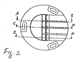
Figur 2- eine Aufsicht auf die Unterflurleuchte aus Figur 1, wobei die Schnitte gemäß Figur 3a bis 3c gekennzeichnet sind,
- Figur 2a
- Schnitt in Richtung AB durch die
Unterflurleuchte aus Figur 3, wobei der Schnitt durch den Steg verläuft, - Figur 2b
- Schnitt in Richtung
EF aus Figur 3, wobei der Schnitt durch den Lichtkanal erfolgt, wobei das Fenster nicht eingesetzt ist, - Figur 2c
- Schnitt in Richtung CD durch den
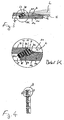
Unterflurleuchte aus Figur 3, wobei der Schnitt unter anderem durch dieVerschraubungsausnehmung 4 verläuft, Figur 3- eine Detailschnittdarstellung durch den Borsteinreflektor mit darin befindlichen Lichtquellefenster und Lichtkanal, wobei das Detail K herausgestellt vergrößert ist, und
Figur 4- eine Anordnung der nebeneinanderliegenden Systeme, welche jeweils aus drei Lichtquellen und zugehörigem Fenster bestehen.
- Figure 1
- 3 shows a top view with two detail sections of an underfloor light according to the invention with four partial light channels,
- Figure 1a and 1b
- Detail pictures from Figure 1,
- Figure 2
- 2 shows a top view of the underfloor lamp from FIG. 1, the cuts being identified according to FIGS. 3a to 3c,
- Figure 2a
- Section in direction AB through the underfloor lamp from FIG. 3, the section running through the web,
- Figure 2b
- Section in the direction EF from FIG. 3, the section being made through the light channel, the window not being inserted,
- Figure 2c
- Section in the direction of the CD through the underfloor lamp from FIG. 3, the section running through the
screw recess 4, among other things, - Figure 3
- a detailed sectional view through the bristle reflector with the light source window and light channel located therein, the detail K being enlarged, and
- Figure 4
- an arrangement of the adjacent systems, each consisting of three light sources and associated window.
Die in den Figuren gleichen Bezugsziffern bezeichnen gleiche oder gleich wirkende Elemente.The same reference numerals in the figures denote the same or elements with the same effect.
Das in den Figuren 1 bis 4 dargestellte bevorzugte Ausführungsbeispiel
der Erfindung umfasst eine Unterflurleuchte 1
mit einem aus Oberteil 11 und (in den Figuren nicht näher
dargestellten) Unterteil gebildeten Gehäuse zur Aufnahme einer
lichtdurchlässigen Abdeckung 7 sowie einer im Oberteil 11
angeordneten Lichtquelle 6, wobei die lichtdurchlässige Abdeckung
ein im Oberteil 11 eingesetztes Prisma 7 aufweist, aus
dem das Lichtbündel L in einer bestimmten Richtung, insbesondere
in einem engen, spitzen Winkelbereich zur Horizontalen H
austritt, und das Prisma 7 gegenüber dem eintretenden Licht
von der Lichtquelle 6 eine hierzu senkrechte Eintrittsfläche
72 und gegenüber dem austretenden Licht L eine schräg gerichtete
Austrittsfläche 72 aufweist. Nach dem erfindungsgemäßen
Ausführungsbeispiel ist in dem Oberteil 11 eine im wesentlichen
horizontalen d. h. gegenüber der Horizontalen H allenfalls
geringfügig abwärts geneigte, und gegenüber der Oberseite
15 des Oberteiles 11 abgesetzte Freifläche 21 ausgebildet
ist, die sich an den unteren Rand 73 der Austrittsfläche
71 des Prismas 7 anschließt und sich bis an den äußeren Rand
13 des Oberteils 11 erstreckt, und das Prisma 7 zwischen dem
Rand 73 der Freifläche und der Oberseite 15 dergestalt schräg
eingesetzt ist, dass die Austrittsfläche 71 des Prismas 7
gegenüber der Horizontalen H einen Winkel von etwa 135° bildet.
In dem vorzugsweise aus Hartmetall oder auch aus bruchfestem
Kunststoff gefertigten Oberteil 11 des Gehäuses ist
wenigstens ein etwa unter einem schrägen Winkel von 45° gegenüber
der Horizontalen H gebildeter Durchbruch 52 vorgesehen,
dessen lichte Weite zur Aufnahme des Prismas 7 in einem
oberen Bereich vergrößert ist, während der untere Bereich 51
des Durchbruches 52 eine geringere lichte Weite zur Aufnahme
der Lichtquelle 6 hat. Prisma 7 und Lichtquelle 6 sind in dem
Durchbruch 52 eingesetzt bzw. festgelegt, und sind somit
vollständig im Oberteil 11 des Gehäuses untergebracht. Der
äußere Rand 53 des den Durchbruch 52 an der Oberseite des
Oberteils 11 abschließenden Bereiches hat eine Randfläche 54,
welche im wesentlichen planparallel und bündig mit der Austrittsfläche
71 des Prismas 7 abschließt (Detail K von Fig.
3).The preferred embodiment shown in Figures 1 to 4
The invention comprises an underfloor lamp 1
with one from top 11 and (not shown in the figures)
shown) lower part formed housing for receiving a
Die Freifläche 21 ist von zumindest einem Steg 31 unterbrochen,
welcher Steg 31 sich von der Oberseite 15 des Gehäuseoberteils
11 in sektionaler Richtung schräg abwärts geneigt
bis zum äußeren Rand 13 des Gehäuseoberteils 11 erstreckt. Im
dargestellten Ausführungsbeispiel sind drei solcher Stege 31
vorgesehen, wobei die Anzahl der Stege 31 auch größer sein
kann. Die Stege 31 bewirken eine Unterteilung der Freifläche
21 zur Ausbildung von Teil-Lichtkanälen 2, wobei im dargestellten
Ausführungsbeispiel vier solcher Teil-Lichtkanäle
vorgesehen sind.The
Insbesondere nach der Darstellung gemäß Fig. 1 und 2 ist ersichtlich,
dass das Gehäuseoberteil 11 an seiner Oberseite 15
außerhalb der Freifläche 21 noch im wesentlichen zwei gegeneinander
geneigte Flächen aufweist, nämlich eine relativ zum
Oberteil 11 etwa mittige Horizontalfläche 32 und eine hieran
außermittig anschließende, radial nach außen abwärts geneigte
Schrägfläche 30, wobei die Freifläche 21 sowohl einen Teil
der Horizontalfläche 32 als auch einen Teil der Schrägfläche
30 herausschneidet. Die Freifläche 21 ist im wesentlichen
glatt ausgebildet, während die Horizontalfläche 32 und/oder
die Schrägfläche 30 strukturiert ausgebildet ist. Beim dargestellten
Ausführungsbeispiel ist die Oberfläche der Schrägfläche
30 in Form von senkrecht zur radialen Richtung ausgerichteten
konzentrischen Rillen 301 strukturiert, welche Rillen
in radialer Richtung einen dreiecksförmigen Querschnitt
aufweisen, wie es schematisch in Fig. 1b dargestellt ist. Die
Oberfläche der Horizontalfläche 32 ist in Form geometrischer
Grundkörper strukturiert, wobei im gezeigten Ausführungsbeispiel
als geometrische Grundkörper vierseitige, nicht rechtwinklige
Pyramiden 321 Anwendung finden, wie es schematisch
in Fig. 1a dargestellt ist. Durch diese Strukturierung der
Oberflächen von Horizontalfläche 32 und Schrägfläche 30 wird
einerseits eine bessere Traktion der Reifen der überfahrenden
Fahrzeuge erreicht und andererseits der Abrieb der Fahrzeugreifen
minimiert.In particular after the representation according to FIGS. 1 and 2 it can be seen
that the
Figur 1 zeigt die erfindungsgemäße Unterflurleuchte 1 in Aufsicht
auf die zu überfahrende Seite (untere Montageseite 14
verdeckt). Das Gehäuseoberteil 11 hat eine im Wesentlichen
geschlossene Form, wobei die Teil-Lichtkanäle 2 in Form von
Ausnehmungen in die geschlossene Form hinein ausgebildet
sind, wobei die Stege 31 zwischen ihnen stehen bleiben. Die
Stege 31 bilden somit teilweise die seitlichen Wandungen der
Teil-Lichtkanäle 2. Die Stege halten so die sonst auf die
Systeme 8 (siehe Figur 3) wirkenden, beim Überfahren auftretenden
mechanische Kräfte ab.Figure 1 shows the underfloor light 1 according to the invention in supervision
on the side to be driven over (lower mounting
Die Unterflurleuchte 1 wird zur Montage auf einem Untergrund,
beispielsweise direkt auf der Fahrbahn als Begrenzungsmarkierung,
vorzugsweise leicht in die Oberfläche der Fahrbahn eingelassen
montiert, so dass die Unterflurleuchte mit ihren
Seitenflächen 12 im Boden eingelassen ist. Hierzu wird das
Gehäuseoberteil 11 durch die Ausnehmungen 4 (siehe Figur 1)
vermittels Schrauben - nicht dargestellt - durch die Durchführungs-Bohrung
41 auf dem Untergrund befestigt. Die Systeme
8 aus Lichtquelle und Fenster sind räumlich nebeneinander mit
jeweils eigenem Teil-Lichtkanal 2 angeordnet. Die Lichtemission
von den Systemen 8 erfolgt im wesentlichen in die gleiche
Richtung in den in Teil-Lichtkanäle 2 unterteilten Lichtkanal,
sodass ein Ausfall selbst mehrerer Systeme die Funktionalität
nicht beeinträchtigt.The underfloor light 1 is used for mounting on a surface,
for example, directly on the road as a boundary marker,
preferably slightly embedded in the surface of the road
mounted so that the underfloor light with their
Side surfaces 12 is embedded in the floor. For this, the
Die Figuren 2 und 2a bis 2c zeigen das Gehäuseoberteil 11 in
mehreren Querschnittsdarstellungen. Figur 2 zeigt hierbei die
Lage der Schnittdarstellungen aus den Figuren 2a bis 2c.Figures 2 and 2a to 2c show the
Figur 2a, welche den Querschnitt aus Figur 2 in Richtung A-C
zeigt, veranschaulicht wie die Schrägfläche 30 zur Horizontalfläche
32 an der Oberseite angewinkelt ist. Die Schrägfläche
geht bis zum äußeren Rand 13 des Gehäuseoberteils 11, an
das sich auch die senkrechte Seitenfläche 12 anschließt. Dargestellt
ist auch der die Lichtquelle und deren Energiezuführung
aufnehmende Hohlraum 5 mit zugehöriger Lichtquellenaussparung
51. Eine Stromkabelzuführung ist so von der Unterseite
14 des Gehäusekörpers möglich.Figure 2a, which is the cross section of Figure 2 in the direction A-C
shows how the
Figur 2b zeigt einen Querschnitt in Richtung E-F aus Figur 2.
Neben der Aussparung 51 für die Lichtquelle ist auch die Aussparung
52 für das Fenster 7 sichtbar. Unmittelbar an die
Fenster-Aussparung schließt sich der Teil-Lichtkanal 2 an,
durch den das aus dem Fenster 7 ausgekoppelte Licht L geleitet
wird (Figur 3). Die Freifläche 21 des Teil-Lichtkanals 2
ist eine zum äußeren Rand 13 des Gehäusekörpers 11 hin abfallende
Schräge (nur wenige Grad, daher nicht dargestellt).FIG. 2 b shows a cross section in the direction E-F from FIG. 2.
In addition to the
Figur 2c zeigt einen Querschnitt in Richtung C-D aus Figur 2,
wobei ein Querschnitt durch die Befestigungsausnehmungen 4
mit Schraubendurchlass 41 sichtbar wird.FIG. 2c shows a cross section in the direction C-D from FIG. 2,
a cross section through the fastening recesses 4
with
Figur 3 zeigt eine Schnittdarstellung durch den Bereich der
Lichtquelle 6 im Hohlraum 5 und 51 sowie das Fenster 7 in
seiner Ausnehmung 52 und den Teil-Lichtkanal 2, durch den das
emittierte Licht L geführt wird. Die montierte Lichtquelle
ist in Form einer Leuchtdiode 6 ausgebildet. Das Fenster 7
ist als Prisma ausgestaltet, dessen Lichteintrittsfläche 72
nicht parallel zur Lichtaustrittsfläche 71 ist. Hierdurch
wird eine das Licht L in die gewünschte Richtung gelenkt und
zudem wird erreicht, dass durch die Anstellung der Lichtaustrittsfläche
71 zur Senkrechten die gewünschte Schmutzableitung
erfolgt. Die Lichteintrittsfläche 72 ist im wesentlichen
senkrecht zur Abstrahlrichtung der Lichtquelle 6 orientiert,
was eine optimale Licht'einkopplung in das Fenster 7 ermöglicht.
Siehe hierzu auch Detaildarstellung K. Figure 3 shows a sectional view through the area of
Light source 6 in the
Figur 4 zeigt schließlich die nebeneinander angeordneten Systeme
8 von Lichtquelle (jeweils drei Leuchtdioden 6) und
Fenster 7. Figure 4 finally shows the systems arranged side by side
8 of light source (three LEDs 6 each) and
- 11
- UnterflurleuchteInground luminaire
- 1111
- Oberteiltop
- 1212
- Seitenflächeside surface
- 1313
- äußerer Randouter edge
- 1414
- Unterseite (Montageseite)Bottom side (mounting side)
- 1515
- Oberseitetop
- 22
- Teil-LichtkanalPart-light channel
- 2121
- Freiflächeopen space
- 3030
- Schrägflächesloping surface
- 301301
- Rillegroove
- 3131
- Stegweb
- 3232
- Horizontalflächehorizontal surface
- 321321
- Pyramidenpyramids
- 44
- Ausnehmungrecess
- 4141
- Durchführungs-BohrungThrough-bore
- 55
- Hohlraumcavity
- 5151
- LichtquellenaussparungLight source recess
- 5252
- Durchbruchbreakthrough
- 5353
- äußerer Randouter edge
- 5454
- Randflächeedge surface
- 66
- Leuchtdiode, LichtquelleLED, light source
- 6161
- Platinecircuit board
- LL
- emittiertes Lichtemitted light
- 77
- Prismaprism
- 7171
- LichtaustrittsflächeLight-emitting surface
- 7272
- LichteintrittsflächeLight entry surface
- 7373
- unterer Randlower margin
- 88th
- System (Lichtquelle und Fenster)System (light source and window)
- HH
- Horizontalehorizontal
Claims (9)
dadurch gekennzeichnet, dass in dem Oberteil (11) eine im wesentlichen horizontale, d.h. gegenüber der Horizontalen allenfalls geringfügig abwärtsgeneigte, und gegenüber der Oberseite (15) des Oberteiles (11) abgesetzte Freifläche (21) ausgebildet ist, die sich an den unteren Rand (73) der Austrittsfläche (71) des Prismas (7) anschließt und sich bis an den äußeren Rand (13) des Oberteils (11) erstreckt, und das Prisma (7) zwischen dem Rand (13) der Freifläche (21) und der Oberseite (15) dergestalt schräg eingesetzt ist, dass die Austrittsfläche (71) des Prismas (7) gegenüber der Horizontalen (H) einen Winkel von etwa 135° bildet.Underfloor light (1) with a housing formed from the upper part (11) and lower part for receiving a translucent cover (7) and a light source (6) and / or light-guiding optics arranged in the upper part (11), the translucent cover (7) has in the upper part (11) inserted prism (7), from which the light beam (2) emerges in a certain direction, in particular in a narrow, acute angular range to the horizontal (H), and the prism (7) with respect to the incoming light vertical entrance surface (72) and an oblique exit surface (71) with respect to the emerging light,
characterized in that in the upper part (11) a substantially horizontal, ie at most slightly downward incline and opposite to the upper side (15) of the upper part (11) is formed free surface (21), which is located at the lower edge ( 73) of the exit surface (71) of the prism (7) and extends to the outer edge (13) of the upper part (11), and the prism (7) between the edge (13) of the free surface (21) and the top (15) is inserted obliquely in such a way that the exit surface (71) of the prism (7) forms an angle of approximately 135 ° with respect to the horizontal (H).
dadurch gekennzeichnet, dass das Prisma (7) in einem im Oberteil (11) des Gehäuses ausgebildeten Durchbruch (52) eingesetzt ist.Underfloor light according to claim 1,
characterized in that the prism (7) is inserted in an opening (52) formed in the upper part (11) of the housing.
dadurch gekennzeichnet, dass die Lichtquelle (6) und/oder die lichtführende Optik ebenfalls in dem Durchbruch (52) im Oberteil (11) des Gehäuses untergebracht ist. Underfloor light according to claim 1 or 2,
characterized in that the light source (6) and / or the light-guiding optics is likewise accommodated in the opening (52) in the upper part (11) of the housing.
dadurch gekennzeichnet, dass die Freifläche (21) von zumindest einem Steg (31) unterbrochen ist, welcher Steg (31) sich von der Oberseite (15) des Gehäuseoberteiles (11) in sektionaler Richtung schräg abwärtsgeneigt bis zum äußeren Rand (13) des Gehäuseoberteiles (11) erstreckt.Underfloor light according to one of claims 1 to 3,
characterized in that the free surface (21) is interrupted by at least one web (31), which web (31) is inclined downwards in a sectional direction from the top (15) of the housing upper part (11) to the outer edge (13) of the housing upper part (11) extends.
dadurch gekennzeichnet, dass der wenigstens eine Steg (31) die Freifläche zur Ausbildung von Teil-Lichtkanälen (2) unterteilt.Underfloor light according to claim 4,
characterized in that the at least one web (31) divides the free area to form partial light channels (2).
dadurch gekennzeichnet, dass das Gehäuseoberteil (11) an seiner Oberseite (15) außerhalb der Freifläche (21) noch im wesentlichen zwei gegeneinander geneigte Flächen aufweist, nämlich eine relativ zum Oberteil (11) etwa mittige Horizontalfläche (32) und eine hieran außermittig anschließende, radial nach außen abwärtsgeneigte Schrägfläche (30), wobei die Freifläche (21) sowohl einen Teil der Horizontalfläche (32) als auch einen Teil der Schrägfläche (31) herausschneidet.Underfloor light according to one of claims 1 to 5,
characterized in that the upper part (11) of the housing (15) outside the free surface (21) still has essentially two surfaces inclined towards each other, namely a horizontal surface (32) approximately central with respect to the upper part (11) and an adjoining one off-center, radially outwardly inclined inclined surface (30), the free surface (21) cutting out both part of the horizontal surface (32) and part of the inclined surface (31).
dadurch gekennzeichnet, dass die Freifläche (21) im wesentlichen glatt ausgebildet ist, während die Horizontal- und/oder Schrägfläche (30, 32) strukturiert ist.Underfloor light according to claim 6,
characterized in that the free surface (21) is substantially smooth, while the horizontal and / or inclined surface (30, 32) is structured.
dadurch gekennzeichnet, dass das Gehäuseoberteil (11) einstückig ausgebildet ist.Underfloor light according to one of claims 1 to 7,
characterized in that the upper housing part (11) is formed in one piece.
dadurch gekennzeichnet, dass mehrere, nämlich wenigstens zwei Prismen (7) räumlich nebeneinander angeordnet sind, wobei die Lichtausstrahlung von den Prismen (7) im wesentlichen in die gleiche Richtung in den von der Freifläche (21) definierten Lichtkanal (2) erfolgt.Underfloor light according to one of claims 1 to 8,
characterized in that several, namely at least two prisms (7) are arranged spatially next to one another, the light being emitted by the prisms (7) essentially in the same direction in the light channel (2) defined by the free surface (21).
Applications Claiming Priority (2)
| Application Number | Priority Date | Filing Date | Title |
|---|---|---|---|
| DE20202407U | 2002-02-15 | ||
| DE20202407U DE20202407U1 (en) | 2002-02-15 | 2002-02-15 | Inground luminaire |
Publications (2)
| Publication Number | Publication Date |
|---|---|
| EP1344867A2 true EP1344867A2 (en) | 2003-09-17 |
| EP1344867A3 EP1344867A3 (en) | 2005-10-26 |
Family
ID=7967870
Family Applications (1)
| Application Number | Title | Priority Date | Filing Date |
|---|---|---|---|
| EP03003334A Withdrawn EP1344867A3 (en) | 2002-02-15 | 2003-02-13 | Lighting fixture flush mounted in the ground |
Country Status (3)
| Country | Link |
|---|---|
| EP (1) | EP1344867A3 (en) |
| AT (1) | AT7277U1 (en) |
| DE (1) | DE20202407U1 (en) |
Families Citing this family (4)
| Publication number | Priority date | Publication date | Assignee | Title |
|---|---|---|---|---|
| AT413560B (en) * | 2001-09-26 | 2006-03-15 | Swarco Futurit Verkehrssignals | ROADWAY MARKER LIGHT |
| EP1367179A1 (en) * | 2002-05-27 | 2003-12-03 | Gifas Electric Gesellschaft m.b.H. | Lighting unit |
| DE10246144A1 (en) * | 2002-10-01 | 2004-04-15 | Garufo Gmbh | Indicator element for road lanes, is set into road surface and has light source mounted on elastic element |
| DE102006057071B3 (en) * | 2006-11-29 | 2008-04-10 | Sven Quitschau | Mineral stone with integrated lighting mechanism for use as functional or decorative lighting in e.g. building, house, external installation, has lighting mechanism fixed in through hole of mineral stone using translucent sealing compound |
Citations (3)
| Publication number | Priority date | Publication date | Assignee | Title |
|---|---|---|---|---|
| DE29712281U1 (en) | 1996-05-23 | 1997-12-04 | Siemens Ag | Luminous device for signaling, marking or marking |
| DE29723372U1 (en) | 1996-05-23 | 1998-08-13 | Siemens Ag | Lighting device for airports, in particular underfloor lighting |
| DE19809253A1 (en) | 1998-03-05 | 1999-09-09 | Aqua Signal Ag | Under-floor lighting with housing |
Family Cites Families (3)
| Publication number | Priority date | Publication date | Assignee | Title |
|---|---|---|---|---|
| CH672830A5 (en) * | 1987-03-16 | 1989-12-29 | Meta Fer Ag | |
| DE4008932A1 (en) * | 1990-03-20 | 1991-09-26 | Siemens Ag | Modular lighting recessed into airport runways - has circular bases with independent light modules for directional beam |
| JP3931414B2 (en) * | 1997-10-31 | 2007-06-13 | 東芝ライテック株式会社 | Recessed beacon lamp and recessed beacon light device |
-
2002
- 2002-02-15 DE DE20202407U patent/DE20202407U1/en not_active Expired - Lifetime
-
2003
- 2003-02-13 EP EP03003334A patent/EP1344867A3/en not_active Withdrawn
- 2003-03-28 AT AT0021703U patent/AT7277U1/en not_active IP Right Cessation
Patent Citations (3)
| Publication number | Priority date | Publication date | Assignee | Title |
|---|---|---|---|---|
| DE29712281U1 (en) | 1996-05-23 | 1997-12-04 | Siemens Ag | Luminous device for signaling, marking or marking |
| DE29723372U1 (en) | 1996-05-23 | 1998-08-13 | Siemens Ag | Lighting device for airports, in particular underfloor lighting |
| DE19809253A1 (en) | 1998-03-05 | 1999-09-09 | Aqua Signal Ag | Under-floor lighting with housing |
Also Published As
| Publication number | Publication date |
|---|---|
| DE20202407U1 (en) | 2002-05-16 |
| AT7277U1 (en) | 2004-12-27 |
| EP1344867A3 (en) | 2005-10-26 |
Similar Documents
| Publication | Publication Date | Title |
|---|---|---|
| DE19851174B4 (en) | Signal light, in particular rear light, of vehicles, preferably motor vehicles | |
| EP3334864B1 (en) | Elongated clamping unit | |
| EP1918480B1 (en) | Handrail with electric illumination sources provided in the handrail | |
| EP2756488B1 (en) | Lighting arrangement, in particular for escape route lighting | |
| EP3211297A1 (en) | Lighting module in particular for road lights | |
| DE102012210444B4 (en) | Vehicle lamp with several deflecting bodies in the reflector | |
| EP1344867A2 (en) | Lighting fixture flush mounted in the ground | |
| AT413560B (en) | ROADWAY MARKER LIGHT | |
| EP1506892A2 (en) | Light with a light guide to be mounted in a door of a vehicle | |
| DE102016111705A1 (en) | InGround lighting device | |
| EP2295851B1 (en) | Light influencing element | |
| EP1657209A1 (en) | Escalator or moving walkway | |
| DE10139002B4 (en) | recessed light | |
| DE102006021963A1 (en) | Light particularly rear light for vehicles preferably motor vehicles, has housing provided with illuminant arranged before reflector | |
| EP2902699B1 (en) | Light unit for lantern-shaped light | |
| EP2927889B1 (en) | Signal transmitter for dispensing a light signal | |
| EP2348250B1 (en) | Linear LED light, in particular LED ring light | |
| DE19738297A1 (en) | Structural or architectural component for showing street curbs | |
| DE19834195C2 (en) | Outdoor lamp with a reflector arrangement | |
| DE3437821A1 (en) | Luminous guide device for road illumination | |
| EP3412963A1 (en) | Transparent component arrangement of a light module and light module comprising such a transparent component arrangement | |
| DE102008039354B4 (en) | lighting bollards | |
| DE2615107A1 (en) | STREET LIGHTS, IN PARTICULAR CENTRAL STRIPE LIGHTS, FOR ONE-WAY Lanes | |
| EP1463651B1 (en) | Vehicle light having a cruciform light distribution | |
| DE202023102393U1 (en) | Barrier boom for a barrier system |
Legal Events
| Date | Code | Title | Description |
|---|---|---|---|
| PUAI | Public reference made under article 153(3) epc to a published international application that has entered the european phase |
Free format text: ORIGINAL CODE: 0009012 |
|
| AK | Designated contracting states |
Kind code of ref document: A2 Designated state(s): AT BE BG CH CY CZ DE DK EE ES FI FR GB GR HU IE IT LI LU MC NL PT SE SI SK TR |
|
| AX | Request for extension of the european patent |
Extension state: AL LT LV MK RO |
|
| PUAL | Search report despatched |
Free format text: ORIGINAL CODE: 0009013 |
|
| AK | Designated contracting states |
Kind code of ref document: A3 Designated state(s): AT BE BG CH CY CZ DE DK EE ES FI FR GB GR HU IE IT LI LU MC NL PT SE SI SK TR |
|
| AX | Request for extension of the european patent |
Extension state: AL LT LV MK RO |
|
| AKX | Designation fees paid | ||
| STAA | Information on the status of an ep patent application or granted ep patent |
Free format text: STATUS: THE APPLICATION IS DEEMED TO BE WITHDRAWN |
|
| 18D | Application deemed to be withdrawn |
Effective date: 20060427 |
|
| REG | Reference to a national code |
Ref country code: DE Ref legal event code: 8566 |