EP1344682A2 - Direction adjustable device for an automobile with a steerring linkage - Google Patents
Direction adjustable device for an automobile with a steerring linkage Download PDFInfo
- Publication number
- EP1344682A2 EP1344682A2 EP03251512A EP03251512A EP1344682A2 EP 1344682 A2 EP1344682 A2 EP 1344682A2 EP 03251512 A EP03251512 A EP 03251512A EP 03251512 A EP03251512 A EP 03251512A EP 1344682 A2 EP1344682 A2 EP 1344682A2
- Authority
- EP
- European Patent Office
- Prior art keywords
- force transmitting
- transmitting member
- adjustable device
- housing
- direction adjustable
- Prior art date
- Legal status (The legal status is an assumption and is not a legal conclusion. Google has not performed a legal analysis and makes no representation as to the accuracy of the status listed.)
- Granted
Links
Images


Classifications
-
- B—PERFORMING OPERATIONS; TRANSPORTING
- B60—VEHICLES IN GENERAL
- B60Q—ARRANGEMENT OF SIGNALLING OR LIGHTING DEVICES, THE MOUNTING OR SUPPORTING THEREOF OR CIRCUITS THEREFOR, FOR VEHICLES IN GENERAL
- B60Q1/00—Arrangement of optical signalling or lighting devices, the mounting or supporting thereof or circuits therefor
- B60Q1/02—Arrangement of optical signalling or lighting devices, the mounting or supporting thereof or circuits therefor the devices being primarily intended to illuminate the way ahead or to illuminate other areas of way or environments
- B60Q1/04—Arrangement of optical signalling or lighting devices, the mounting or supporting thereof or circuits therefor the devices being primarily intended to illuminate the way ahead or to illuminate other areas of way or environments the devices being headlights
- B60Q1/06—Arrangement of optical signalling or lighting devices, the mounting or supporting thereof or circuits therefor the devices being primarily intended to illuminate the way ahead or to illuminate other areas of way or environments the devices being headlights adjustable, e.g. remotely-controlled from inside vehicle
- B60Q1/08—Arrangement of optical signalling or lighting devices, the mounting or supporting thereof or circuits therefor the devices being primarily intended to illuminate the way ahead or to illuminate other areas of way or environments the devices being headlights adjustable, e.g. remotely-controlled from inside vehicle automatically
- B60Q1/12—Arrangement of optical signalling or lighting devices, the mounting or supporting thereof or circuits therefor the devices being primarily intended to illuminate the way ahead or to illuminate other areas of way or environments the devices being headlights adjustable, e.g. remotely-controlled from inside vehicle automatically due to steering position
-
- B—PERFORMING OPERATIONS; TRANSPORTING
- B60—VEHICLES IN GENERAL
- B60Q—ARRANGEMENT OF SIGNALLING OR LIGHTING DEVICES, THE MOUNTING OR SUPPORTING THEREOF OR CIRCUITS THEREFOR, FOR VEHICLES IN GENERAL
- B60Q2300/00—Indexing codes for automatically adjustable headlamps or automatically dimmable headlamps
- B60Q2300/10—Indexing codes relating to particular vehicle conditions
- B60Q2300/12—Steering parameters
- B60Q2300/122—Steering angle
Definitions
- the invention relates to a direction adjustable device, more particularly to a direction adjustable device for an automobile with a steering linkage.
- GB 2346435A discloses a rotatable automobile front lamp apparatus that is capable of rotating in accordance with the steering of a set of front wheels of an automobile so as to reduce the possibility of an accident and enhance safety especially when driving along a winding road.
- the main object of the present invention is to provide a direction adjustable device for an automobile with a steering linkage that can be easily installed in an automobile without occupying too much space.
- a direction adjustable device of this invention is adapted to be installed in an automobile.
- the automobile has an automobile body, a set of automobile wheels mounted on the automobile body, a steering wheel, and a steering linkage interconnecting the steering wheel and the automobile wheels.
- the direction adjustable device comprises a turnable unit, a motor drive unit, and a sensor assembly.
- the motor drive unit is adapted to be mounted to the automobile body, and is coupled to the turnable unit for driving the turnable unit to turn.
- the sensor assembly includes a housing, a force transmitting member, a first cable, a rotary control switch, a signal processing unit, and a reversing member.
- the housing is adapted to be mounted to the automobile body adjacent to the steering linkage.
- the force transmitting member is mounted pivotally to the housing.
- the first cable has a first end connected to the force transmitting member, and a second end adapted to be connected to the steering linkage such that movement of the steering linkage in a first lateral direction results in pivoting movement of the force transmitting member from an initial position in a first rotational direction.
- the rotary control switch is mounted to the housing, and is coupled to the force transmitting member such that pivoting movement of the force transmitting member is transmitted to the rotary control switch to enable the rotary control switch to generate a corresponding electrical output.
- the signal processing unit is connected electrically to the motor drive unit and the rotary control switch, receives the electrical output of the rotary control switch, determines direction and extent of pivoting movement of the force transmitting member from the electrical output, and controls the motor drive unit to drive the turnable unit to turn by an angle corresponding to the direction and extent of pivoting movement of the force transmitting member.
- the reversing member is coupled to the force transmitting member, and is adapted to be connected to the steering linkage such that movement of the steering linkage in a second lateral direction, which is opposite to the first lateral direction, results in pivoting movement of the first transmitting member from the initial position in a second rotational direction, which is opposite to the first rotational direction.
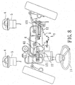
- the first preferred embodiment of a direction adjustable device 1 is shown to be adapted to be installed in an automobile (not shown) .
- the automobile has an automobile body (not shown) , two automobile wheels 14, a steering wheel 11, and a steering linkage 12 interconnecting the steering wheel 11 and the automobile wheels 14.
- the steering linkage 12 includes a swing arm 15 connected to the steering wheel 11, and left and right tie-rods 121 connected to the automobile wheels 14, and a steering assist unit 13 connected to the swing arm 15 and the tie-rods 121 and provided with a hydraulic cylinder 131.
- the direction adjustable device 1 is installed in a position proximate to the tie-rods 121 and the hydraulic cylinder 131, and comprises two turnable units 4, two motor drive units 5, and a sensor assembly 2.
- the sensor assembly 2 includes a housing 21, a force transmitting member 24, a first cable 3, a rotary control switch 22, a signal processing unit 23, and a reversing member 4.
- the housing 21 is adapted to be mounted to the automobile body (not shown) adjacent to the steering linkage 12, and includes a flat top plate 211, a surrounding plate 212 extending downwardly from a periphery of the top plate 211, and a cover plate 213 disposed on bottom of the surrounding plate 212 and parallel to the top plate 211.
- the top, surrounding and cover plates 211, 212, 213 cooperatively define a receiving chamber 214.
- the top plate 211 has a plurality of upright screw posts 2110, and includes a rear part 215 and a front part 216 opposite to and wider than that of the rear part 215.
- the surrounding plate 212 is formed with a notch 217 at the rear part 215 of the top plate 211.
- the front part 216 of the top plate 211 is formed with a longitudinal guide slot 218.
- the cover plate 213 is formed with a plurality of through holes 2130, and is fastened to the top plate 211 by a plurality of screws 8 that pass through the through holes 2130 in the cover plate 213 and that engage the upright screw posts 2110 on the top plate 211.
- the force transmitting member 24 is disposed in the receiving chamber 214, and is mounted pivotally on the top plate 211 of the housing 21.
- the force transmitting member 24 includes a telescopic rod 242 with opposite first and second ends 2421, 2422, a driving gear 241 fixed to the first end 2421 of the rod 242 and mounted rotatably in the receiving chamber 214, and a cable seat 244 mounted on the second end 2422 (see Figure 6) of the rod 242.
- the cable seat 244 is formed with a guide stud 245 and two pivot holes 246, 247 disposed on opposite sides of the guide stud 245.
- the guide stud 245 projects into the guide slot 218 in the front part 216 of the top plate 211 so as to guide pivoting movement of the force transmitting member 24 in the housing 21.
- the first cable 3 includes a tubular sleeve 31, a wire member 32 freely movable along the length of the tubular sleeve 31, and a cable frame 33 mounted on the hydraulic cylinder 131.
- the sleeve 31 has two ends secured on the housing 21 and the cable frame 33, respectively.
- the wire member 32 has a first end 322 that extends into the housing 21 and that is fastened into one of the pivot holes 246, 247 in the cable seat 244. of the force transmitting member 24, and a second end 321 opposite to the first end 322.
- the second end 321 is adapted to be connected to one of the tie-rods 121 such that movement of the steering linkage 12 in a first lateral direction results in pivoting movement of the force transmitting member 24 from an initial position in a first rotational direction (R1) (see Figure 3).
- the rotary control switch 22 is mounted on a rear extension of the rear part 215 of the top plate 211, and includes a rotary sensor 221 clamped between two clamp plates 220, a sensor rod 222, a signal wire 223, and a driven gear 224 mounted on the sensor rod 222.
- the sensor rod 222 extends through the rear part 215 of the top plate 211, is disposed adjacent to the notch 217 in the surrounding plate 212, and is operably associated with the rotary sensor 221.
- the driven gear 224 meshes with the driving gear 241 of the force transmitting member 24 such that pivoting movement of the force transmitting member 24 is transmitted to the rotary control switch 22 so as to enable the latter to generate a corresponding electrical output in a known manner.
- the signal processing unit 23 is connected electrically to the motor drive units 5 and to the rotary control switch 22 via the signal wire 223, receives the electrical output of the rotary control switch 22, determines direction and extent of pivoting movement of the force transmitting member 24 from the electrical output, and controls each motor drive unit 5 to drive the corresponding turnable unit 4 to turn by an angle corresponding to the direction and extent of pivoting movement of the force transmitting member 24.
- the reversing member 6, in this embodiment, is a torsional spring which is coupled to the housing 21 and the sensor rod 222 of the rotary control switch 22 so as to bias the force transmitting member 24 to turn in the second rotational direction (R2), as best illustrated in Figure 3.
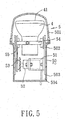
- the motor drive units 5, as best shown in Figures 1, 4 and 5, are adapted to be mounted separately on left and right front parts of the automobile body (not shown) .
- Each of the motor drive units 5 includes an outer casing 50, a motor support frame 51 secured in the outer casing 50, a motor unit 52 mounted on the motor support frame 51 and connected electrically to the signal processing unit 23, and a first sector gear 53 coupled to the motor unit 52.
- the outer casing 50 of each motor drive unit 5 is a lamp housing, and includes a front transparent lamp cover 501, a cover support 502 connected to the lamp cover 501, and a back cover 503 connected to the cover support 502. The lamp cover 501, the cover support 502, and the back cover 503 cooperate to confine a receiving space 504.
- Each of the turnable units 4 in this embodiment is a lamp, and includes a rotatable base frame 54 mounted pivotally in the outer casing 50, a second sector gear 55 mounted on the base frame 54 and meshing with the first sector gear 53, a reflector 41, and a light bulb (not shown).
- a rotatable base frame 54 mounted pivotally in the outer casing 50
- a second sector gear 55 mounted on the base frame 54 and meshing with the first sector gear 53
- a reflector 41 mounted on the base frame 54 and meshing with the first sector gear 53
- a reflector 41 mounted on the base frame 54 and meshing with the first sector gear 53
- a reflector 41 mounted on the base frame 54 and meshing with the first sector gear 53
- a reflector 41 mounted on the base frame 54 and meshing with the first sector gear 53
- a reflector 41 mounted on the base frame 54 and meshing with the first sector gear 53
- a reflector 41 mounted on the base frame 54 and meshing with the first sector gear 53
- the second preferred embodiment of a direction adjustable device 1 for an automobile having a steering linkage 12 is shown to be substantially similar in construction to the first preferred embodiment.
- the reversing member 6 includes a flexible second cable having a first end 61 fastened into the other one of the pivot holes 246, 247 of the force transmitting member 24, and a second end 62 adapted to be connected to the other one of the tie-rods 121 such that subsequent movement of the steering linkage 12 in a second lateral direction opposite to the first lateral direction results in corresponding pivoting movement of the force transmitting member 24.
- each motor drive unit 5 should not be limited to the disclosed embodiment. What is important is that the motor drive unit 5 can rotate the turnable unit 4 synchronously with the steering wheel 11.
- the third preferred embodiment of a direction adjustable device 1 for an automobile having a steering linkage 12 is shown in Figure 10 to be substantially similar to the first preferred embodiment, the main difference residing in the construction of the turnable unit 4.
- the turnable unit 4 is an infrared camera, and a monitor 42 is electrically connected to the camera 4 and is disposed adjacent to the steering wheel 11.
- the camera 4 rotates synchronously with the steering wheel 11, and the images captured by the camera 4 are transmitted to the monitor 42 to enable the driver to view the road conditions.
- the turnable unit 4 can also be in the form of another device with a sensor function.
- the fourth preferred embodiment of a direction adjustable device 1 for an automobile having a steering linkage is shown to be substantially similar to the first preferred embodiment.
- the position of the reversing member 6 in the sensor assembly 2 is changed, and the cover plate 213 of the housing 21 is formed with a hole 2131.
- the reversing member 6 is coupled to the force transmitting member 24, and is adapted to be connected to the steering linkage such that movement of the steering linkage in a second lateral direction results in pivoting movement of the force transmitting member 24 from the initial position in a second rotational direction.
- the driving gear 241 of the force transmitting member 24 has a fixed bottom post portion 248 that extends through the hole 2131.
- the reversing member 6 includes a torsional spring that is sleeved on the bottom post portion 248 of the driving gear 241 and that is connected to the housing 21.
- the housing 21 further includes a hollow cylinder 219, which covers the bottom post portion 248 of the driving gear 241 and which has a closed bottom end 2191 and an open top end that is fixed on the cover plate 213.
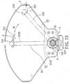
- the fifth preferred embodiment of a direction adjustable device 1 for an automobile having a steering linkage is shown to be substantially similar to the fourth preferred embodiment, the main difference residing in the configuration of the housing 21 of the sensor assembly 2 and the construction of the force transmitting member 24.
- the housing 21 is shaped like a sector.
- the force transmitting member 24 includes a fixed-length rod 242 with first and second ends 2421, 2422.
- the driving gear 241 is mounted on the first end 2421, and meshes with the driven gear 224 of the rotary control switch 22, and a cable seat 244 mounted on the second end 2422 of the fixed-length rod 242 and connected to the first end 322 of the first cable 3.
- R1 first rotational direction
- the sixth preferred embodiment of a direction adjustable device 1 for an automobile having a steering linkage is shown in Figures 14 and 15 to be substantially similar to the fourth preferred embodiment, the main difference residing in the configuration of the housing 21 of the sensor assembly 2 and the construction of the force transmitting member 24.
- the force transmitting member 24 includes a driving gear 241, and a reel 25 connected coaxially and fixedly to the driving gear 241.
- the top plate 211 of the housing 21 is formed with a hole 2111.
- the driving gear 241 is mounted pivotally in the housing 21, meshes with the driven gear 224 of the rotary control switch 22, and includes a fixed top post portion 248 that extends through the hole 2111 in the top plate 211 of the housing 21.
- the first cable 3 is wound around the reel 25.
- the reversing member 6 includes a torsional spring that is sleeved on the top post portion 248 of the driving gear 241 and that is connected to the housing 21.
- the housing 21 further includes a hollow cylinder 219, which covers the top post portion 248 of the driving gear 241 and which has a closed top end 2191 and an open bottom end that is fixed on the top plate 211.
- the seventh preferred embodiment of a direction adjustable device 1 for an automobile having a steering linkage is shown to be substantially similar to the fourth preferred embodiment, the main difference residing in the construction of the sensor assembly 2 .
- the force transmitting member 24 includes a driving gear 241.
- the sensor assembly 2 includes a rack 242.
- the driving gear 241 is mounted pivotally in the housing 21, and meshes with the driven gear 224 of the rotary control switch 22.
- the rack 242 is disposed movably in the housing 21, and meshes with the driving gear 241.
- the first end 322 of the first cable 3 is fastened to an end of the rack 242.
- the front part 216 of the top plate 211 is formed with a longitudinal guide slot 218 to limit lateral movement of the rack 242 .
- the reversing member 6 is coupled to the housing 21 and the force transmitting member 24, thereby biasing the force transmitting member 24 to turn in the second rotational direction.
- the driving gear 241 meshes with the driven gear 224, thereby transmitting the direction and extent of pivoting movement to the rotary control switch 22 via the driven gear 224, and thereby activating the burnable units to turn synchronously with the steering wheel.
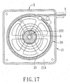
- the eighth preferred embodiment of a direction adjustable device 1 for an automobile having a steering linkage is shown in Figures 17 and 18 to be substantially similar to the sixth preferred embodiment. Only in this embodiment, the dimension of the sensor assembly 2 is reduced.
- the force transmitting member 24 includes a reel 25 disposed in the receiving chamber 214 of the housing 21.
- the first cable 3 is similarly wound around the reel 25 of the force transmitting member 24.
- the cover plate 213 of the housing 21 is formed with a hole 2131, and is parallel to the top plate 211.
- the sensor assembly 2 includes a rotary control switch 22 installed on the cover plate 213, and includes a sensor rod 222 that extends through the hole 2131 in the cover plate 213 and into the receiving chamber 214.
- the reel 25 is sleeved fixedly around the sensor rod 222 .
- the reversing member 6 is a torsional spring which is connected to the cover plate 213 and the reel 25. Because of the function of the reversing member 6, the reel 25 can be biased to turn in a second rotational direction.
- the rotary control switch 22 is directly mounted on the reel 25 so as to rotate synchronously with the reel 25 and so as to reduce the volume of the housing 21 so that the direction adjustable device 1 can be mounted more conveniently in an automobile.
Landscapes
- Engineering & Computer Science (AREA)
- Mechanical Engineering (AREA)
- Steering Controls (AREA)
- Lighting Device Outwards From Vehicle And Optical Signal (AREA)
- Studio Devices (AREA)
Abstract
Description
Claims (16)
- A direction adjustable device (1) adapted to be installed in an automobile having an automobile body, a set of automobile wheels (14) mounted on the automobile body, a steering wheel (11), and a steering linkage (12) interconnecting the steering wheel(11)and the automobile wheels (14), said direction adjustable device (1) characterized by:a turnable unit (4);a motor drive unit (5) adapted to be mounted to the automobile body and coupled to said turnable unit (4) for driving said turnable unit (4) to turn; anda sensor assembly (2) including
a housing (21) adapted to be mounted to the automobile body adjacent to the steering linkage (12),
a force transmitting member (24) mounted pivotally to said housing (21),
a first cable (3) having a first end (322) connected to said force transmitting member (24) , and a second end (321) adapted to be connected to the steering linkage (12) suchthat movement of the steering linkage (12) in a first lateral direction results in pivoting movement of said force transmitting member (24) from an initial positionin a first rotational direction (R1),
a rotary control switch (22) mounted to said housing (21) and coupled to said force transmitting member (24) such that pivoting movement of said force transmitting member (24) is transmitted to said rotary control switch (22) to enable said rotary control switch (22) to generate a corresponding electrical output,
a signal processing unit (23) connected electrically to said motor drive unit (5) and said rotary control switch (22), said signal processing unit (23) receiving the electrical output of said rotary control switch (22), determining direction and extent of pivoting movement of said force transmitting member (24 ) from the electrical output, and controlling said motor drive unit (5) to drive said turnable unit (4) to turn by an angle corresponding to the direction and extent of pivoting movement of said force transmitting member (24), and
a reversing member (6) coupled to said force transmitting member (24) and adapted to be connected to the steering linkage (12) such that movement of the steering linkage (12) in a second lateral direction, which is opposite to said first lateral direction, results in pivoting movement of said force transmitting member (24) from the initial position in a second rotational direction (R2), which is opposite to said first rotational direction (R1). - The direction adjustable device (1) as claimed in Claim 1, characterized in that said reversing member (6) includes a torsional spring, which is coupled to said housing (21) and said force transmitting member (24) so as to bias said force transmitting member (24) to turn in said second rotational direction (R2).
- The direction adjustable device (1) as claimed in Claim 1, characterized in that said reversing member (6) includes a second cable having a first end (61) connected to said force transmitting member (24) and a second end (62) adapted to be connected to the steering linkage (12) such that movement of the steering linkage (12) in a second lateral direction results in the pivoting movement of said force transmitting member (24) in the second rotational direction (R2).
- The direction adjustable device (1) as claimed in Claim 1, characterized in that said rotary control switch (22) includes a rotary sensor (221) , a sensor rod (222) operably associated with said rotary sensor (221) , and a driven gear (224) mounted on said sensor rod (222).
- The direction adjustable device (1) as claimed in Claim 4, further characterized in that said force transmitting member (24) includes a driving gear (241) mounted pivotally in said housing (21) and meshing with said driven gear (224), and a reel (25) connected coaxially and fixedly to said driving gear (241), said first cable (3) being wound around said reel (25).
- The direction adjustable device (1) as claimed in Claim 4, further characterized in that said force transmitting member (24) includes a driving gear (241) mounted pivotally in said housing (21) and meshing with said driven gear (224), said sensor assembly (2) further including a rack (242) that is disposed movably in said housing (21) and that meshes with said driving gear (241), said first end (322) of said first cable (3) being fastened to an end of said rack (242).
- The direction adjustable device (1) as claimed in Claim 4, further characterized in that said force transmitting member (24) includes a fixed-length rod (242) with first and second ends (2421, 2422), a driving gear (241) mounted on said first end (2421) of said fixed-length rod (242) and meshing with said driven gear (224), and a cable seat (244) mounted on said second end (2422) of said fixed-length rod (242) and connected to said first end (322) of said first cable (3).
- The direction adjustable device (1) as claimed in Claim 4, further characterized in that said force transmitting member (24) includes a telescopic rod (242) with first and second ends (2421, 2422), a driving gear (241) mounted on said first end (2421) of said telescopic rod (242) and meshing with said driven gear (224), and a cable seat (244) mounted on said second end (2422) of said telescopic rod (242) and connected to said first end (322) of said first cable (3).
- The direction adjustable device (1) as claimed in Claim 1, characterized in that said housing (21) includes a top plate (211), a surrounding plate (212) extending downwardly from a periphery of said top plate (211), and a cover plate (213) disposed on bottom of said surrounding plate (212), said top, surrounding and cover plates (211, 212, 213) cooperatively defining a receiving chamber (214) , said force transmitting member (24) being disposed in said receiving chamber (214), said driving gear (241) being mounted rotatably in said receiving chamber (214).
- The direction adjustable device (1) as claimed in Claim 9, further characterized in that said top plate (21-1) is formed with a longitudinal guide slot (218), and said cable seat (244) is formed with a guide stud (245) that projects into said guide slot (218) to guide pivoting movement of said force transmitting member (24) in said housing (21).
- The direction adjustable device (1) as claimed in Claim 9, further characterized in that said cover plate (213) is formed with a hole (2131), said driving gear (241) having a fixed bottom post portion (248) that extends through said hole (2131) in said cover plate (213), said reversing member (6) including a torsional spring that is sleeved on said bottom post portion (248) of said driving gear (241) and that is connected to said housing (21), said housing (21) further including a hollow cylinder (219) , which covers said bottom post portion (248) of said driving gear (241) and which has a closed bottom end (2191) and an open top end that is fixed on said cover plate (213).
- The direction adjustable device (1) as claimed in Claim 1, characterized in that said motor drive unit (5) includes an outer casing (50), a motor unit (52) disposed in said outer casing (50) and connected electrically to said signal processing unit (23), and a first sector gear (53) coupled to said motor unit (52).
- The direction adjustable device (1) as claimed in Claim 12, further characterized in that said turnable unit (4) includes a base frame (54) mounted pivotally in said outer casing (50), and a second sector gear (55) mounted on said base frame (54) and meshing with said first sector gear (53) .
- The direction adjustable device (1) as claimed in Claim 1, characterized in that said turnable unit (4) is a lamp.
- The direction adjustable device (1). as claimed in Claim 1, characterized in that said turnable unit (4) is a camera.
- The direction adjustable device (1) as claimed in Claim 1, characterized in that saidhousing (21) includes a top plate (211), a surrounding plate (212) extending downwardly from a periphery of said top plate (211), and a cover plate (213) that is disposed fixedly on a bottom of said surrounding plate (212) and that is parallel to said top plate (211) , said top, surrounding and cover plates (211, 212, 213) cooperatively defining a receiving chamber (214), said force transmitting member (24) including a reel (25) disposed in said receiving chamber (214), said first cable (3) being wound around said reel (25) , said rotary control switch (22) being installed on said cover plate ( 213 ) , and including a sensor rod (222) that extends through said cover plate (213) and into said receiving chamber (214) and that rotates synchronously with said reel (25).
Applications Claiming Priority (4)
| Application Number | Priority Date | Filing Date | Title |
|---|---|---|---|
| GB0206045A GB2386411B (en) | 2002-03-14 | 2002-03-14 | Direction adjustable device for an automobile with a steering linkage |
| GB0206045 | 2002-03-14 | ||
| GB0217646A GB2386412B (en) | 2002-03-14 | 2002-07-30 | Direction adjustable device for an automobile with a steering linkage |
| GB0217646 | 2002-07-30 |
Publications (3)
| Publication Number | Publication Date |
|---|---|
| EP1344682A2 true EP1344682A2 (en) | 2003-09-17 |
| EP1344682A3 EP1344682A3 (en) | 2006-05-10 |
| EP1344682B1 EP1344682B1 (en) | 2008-08-20 |
Family
ID=27767107
Family Applications (1)
| Application Number | Title | Priority Date | Filing Date |
|---|---|---|---|
| EP03251512A Expired - Lifetime EP1344682B1 (en) | 2002-03-14 | 2003-03-12 | Direction adjustable device for an automobile with a steerring linkage |
Country Status (4)
| Country | Link |
|---|---|
| US (1) | US6767119B2 (en) |
| EP (1) | EP1344682B1 (en) |
| JP (1) | JP2004001703A (en) |
| CN (1) | CN100506607C (en) |
Cited By (1)
| Publication number | Priority date | Publication date | Assignee | Title |
|---|---|---|---|---|
| FR2768095A1 (en) * | 1997-09-09 | 1999-03-12 | Chian Yin Tseng | AUTOMOTIVE AND SITE ANGLE ADJUSTMENT PROJECTOR ASSEMBLY |
Families Citing this family (13)
| Publication number | Priority date | Publication date | Assignee | Title |
|---|---|---|---|---|
| CN100425473C (en) * | 2004-11-01 | 2008-10-15 | 吴胜隆 | Automobile auxiliary lamp capable of free rotation |
| CN100509483C (en) * | 2005-08-15 | 2009-07-08 | 堤维西交通工业股份有限公司 | Driving method of vehicle lamp rotating device |
| TW200804113A (en) * | 2006-07-12 | 2008-01-16 | Quan-Ying Ceng | Rotatable vehicle headlamp capable of calibrating rotation degree |
| DE102007007466A1 (en) * | 2007-02-15 | 2008-08-21 | GM Global Technology Operations, Inc., Detroit | Headlamp assembly, method for operating a headlamp assembly and motor vehicle |
| CN101913337A (en) * | 2010-07-20 | 2010-12-15 | 江苏文光车辆附件有限公司 | Rotating mechanism convenient to repair coach headlight |
| ITMI20111469A1 (en) * | 2011-08-01 | 2013-02-02 | Piaggio & C Spa | ADJUSTMENT SYSTEM FOR THE HEADLIGHTS OF A TILTING VEHICLE WITH A ROLLIO MECHANISM |
| KR20140015029A (en) * | 2012-07-27 | 2014-02-06 | 현대모비스 주식회사 | Head lamp for vehicle and vehicle comprising the same |
| CN104442544A (en) * | 2015-01-02 | 2015-03-25 | 江苏新瑞峰信息科技有限公司 | Automobile illuminating apparatus |
| CN105416175B (en) * | 2015-10-20 | 2019-05-03 | 广州汽车集团乘用车有限公司 | Reversing and merging auxiliary system and auxiliary method |
| CN106080370B (en) * | 2016-08-19 | 2018-11-09 | 林淑录 | A kind of regulating device of turn signal |
| CN108279544B (en) * | 2018-01-30 | 2020-10-23 | 东莞市闻誉实业有限公司 | photography light stand |
| CN108644660B (en) * | 2018-05-14 | 2020-02-04 | 安徽卡澜特车灯科技有限公司 | Double-light source lamp |
| CN110985965A (en) * | 2019-12-06 | 2020-04-10 | 陈文健 | Intelligent street lamp lighting system based on thing networking |
Family Cites Families (10)
| Publication number | Priority date | Publication date | Assignee | Title |
|---|---|---|---|---|
| US2941117A (en) * | 1959-10-27 | 1960-06-14 | Page Hayden J | Mechanically steerable and electronically automatic headlighting system |
| FR2240617A5 (en) * | 1973-08-06 | 1975-03-07 | Citroen Sa | |
| EP0138217B1 (en) * | 1983-10-14 | 1988-01-27 | Ichikoh Industries Limited | Apparatus for adjusting the inclination of the automobile headlamp |
| CN2053171U (en) * | 1989-08-24 | 1990-02-21 | 庞达 | Synchronous sway device for car headlights |
| CN2086686U (en) * | 1990-09-05 | 1991-10-16 | 游文军 | Automatic turn-indicating light of vehicle |
| US5099400A (en) * | 1990-12-05 | 1992-03-24 | Lee Hyun J | Headlight moving apparatus for a motor vehicle |
| CN2097122U (en) * | 1991-06-05 | 1992-02-26 | 朱永齐 | Moveable headlight for automobile |
| FR2714458B1 (en) * | 1993-12-23 | 1996-03-08 | Peugeot | Device for controlling the speed of a motor vehicle. |
| GB2329010B (en) * | 1997-09-09 | 2000-03-22 | Tseng Chian Yin | Adjustable vehicle headlamp |
| GB2346435B (en) * | 1999-02-04 | 2002-11-06 | Chian-Yin Tseng | Rotatable automobile front lamp apparatus |
-
2003
- 2003-02-20 CN CNB031054145A patent/CN100506607C/en not_active Expired - Fee Related
- 2003-03-11 JP JP2003065250A patent/JP2004001703A/en active Pending
- 2003-03-11 US US10/387,181 patent/US6767119B2/en not_active Expired - Fee Related
- 2003-03-12 EP EP03251512A patent/EP1344682B1/en not_active Expired - Lifetime
Cited By (1)
| Publication number | Priority date | Publication date | Assignee | Title |
|---|---|---|---|---|
| FR2768095A1 (en) * | 1997-09-09 | 1999-03-12 | Chian Yin Tseng | AUTOMOTIVE AND SITE ANGLE ADJUSTMENT PROJECTOR ASSEMBLY |
Also Published As
| Publication number | Publication date |
|---|---|
| CN100506607C (en) | 2009-07-01 |
| EP1344682A3 (en) | 2006-05-10 |
| JP2004001703A (en) | 2004-01-08 |
| EP1344682B1 (en) | 2008-08-20 |
| US6767119B2 (en) | 2004-07-27 |
| CN1445119A (en) | 2003-10-01 |
| US20030173139A1 (en) | 2003-09-18 |
Similar Documents
| Publication | Publication Date | Title |
|---|---|---|
| EP1344682B1 (en) | Direction adjustable device for an automobile with a steerring linkage | |
| US8056437B2 (en) | Electric steering column lock with single direction actuator travel | |
| US7540216B2 (en) | Electrical control device for motor driven derailleur for bicycle | |
| EP2033875B1 (en) | Vehicle steering apparatus with retractable steering column | |
| EP2033874B1 (en) | Vehicle steering apparatus | |
| JP3772156B2 (en) | Control device for bicycle transmission | |
| US8147107B2 (en) | Headlight rotating device for vehicle | |
| JP2005239123A (en) | Derailleur for bicycle | |
| JPH01190578A (en) | Steering device | |
| JPS639498Y2 (en) | ||
| US11400992B2 (en) | Windscreen device for saddled vehicle | |
| GB2386412A (en) | Direction adjustable device for an automobile with a steering linkage | |
| AU2003200987B2 (en) | Direction adjustable device for an automobile with a steering linkage | |
| KR100563930B1 (en) | Direction adjusting device in a vehicle having a steering link device | |
| JP2913228B2 (en) | Outboard motor | |
| JPH0648368A (en) | Motor-driven transmission for bicycle | |
| JP2001322485A (en) | Automotive outside mirror device with built-in lamp | |
| JPH0648369A (en) | Motor-driven transmission for bicycle | |
| JPS6325267Y2 (en) | ||
| JP2684052B2 (en) | Method and device for controlling headlight irradiation direction of motorcycle | |
| JP4180712B2 (en) | Mirror position detector | |
| JP4799354B2 (en) | Switch device for vehicle | |
| KR970037422A (en) | Steering Angle Adaptive Headlight Control | |
| KR0149351B1 (en) | Power door mirrors for cars | |
| JPH07165127A (en) | Body tilting device of small vehicle |
Legal Events
| Date | Code | Title | Description |
|---|---|---|---|
| PUAI | Public reference made under article 153(3) epc to a published international application that has entered the european phase |
Free format text: ORIGINAL CODE: 0009012 |
|
| AK | Designated contracting states |
Kind code of ref document: A2 Designated state(s): AT BE BG CH CY CZ DE DK EE ES FI FR GB GR HU IE IT LI LU MC NL PT RO SE SI SK TR |
|
| AX | Request for extension of the european patent |
Extension state: AL LT LV MK |
|
| PUAL | Search report despatched |
Free format text: ORIGINAL CODE: 0009013 |
|
| AK | Designated contracting states |
Kind code of ref document: A3 Designated state(s): AT BE BG CH CY CZ DE DK EE ES FI FR GB GR HU IE IT LI LU MC NL PT RO SE SI SK TR |
|
| AX | Request for extension of the european patent |
Extension state: AL LT LV MK |
|
| 17P | Request for examination filed |
Effective date: 20060929 |
|
| 17Q | First examination report despatched |
Effective date: 20061201 |
|
| AKX | Designation fees paid |
Designated state(s): AT BE BG CH CY CZ DE DK EE ES FI FR GR HU IE IT LI LU MC NL PT RO SE SI SK TR |
|
| GRAP | Despatch of communication of intention to grant a patent |
Free format text: ORIGINAL CODE: EPIDOSNIGR1 |
|
| GRAS | Grant fee paid |
Free format text: ORIGINAL CODE: EPIDOSNIGR3 |
|
| GRAA | (expected) grant |
Free format text: ORIGINAL CODE: 0009210 |
|
| AK | Designated contracting states |
Kind code of ref document: B1 Designated state(s): AT BE BG CH CY CZ DE DK EE ES FI FR GR HU IE IT LI LU MC NL PT RO SE SI SK TR |
|
| REG | Reference to a national code |
Ref country code: CH Ref legal event code: EP |
|
| REG | Reference to a national code |
Ref country code: IE Ref legal event code: FG4D |
|
| REF | Corresponds to: |
Ref document number: 60322996 Country of ref document: DE Date of ref document: 20081002 Kind code of ref document: P |
|
| PG25 | Lapsed in a contracting state [announced via postgrant information from national office to epo] |
Ref country code: NL Free format text: LAPSE BECAUSE OF FAILURE TO SUBMIT A TRANSLATION OF THE DESCRIPTION OR TO PAY THE FEE WITHIN THE PRESCRIBED TIME-LIMIT Effective date: 20080820 Ref country code: ES Free format text: LAPSE BECAUSE OF FAILURE TO SUBMIT A TRANSLATION OF THE DESCRIPTION OR TO PAY THE FEE WITHIN THE PRESCRIBED TIME-LIMIT Effective date: 20081201 |
|
| PG25 | Lapsed in a contracting state [announced via postgrant information from national office to epo] |
Ref country code: FI Free format text: LAPSE BECAUSE OF FAILURE TO SUBMIT A TRANSLATION OF THE DESCRIPTION OR TO PAY THE FEE WITHIN THE PRESCRIBED TIME-LIMIT Effective date: 20080820 Ref country code: SI Free format text: LAPSE BECAUSE OF FAILURE TO SUBMIT A TRANSLATION OF THE DESCRIPTION OR TO PAY THE FEE WITHIN THE PRESCRIBED TIME-LIMIT Effective date: 20080820 Ref country code: AT Free format text: LAPSE BECAUSE OF FAILURE TO SUBMIT A TRANSLATION OF THE DESCRIPTION OR TO PAY THE FEE WITHIN THE PRESCRIBED TIME-LIMIT Effective date: 20080820 |
|
| PG25 | Lapsed in a contracting state [announced via postgrant information from national office to epo] |
Ref country code: BE Free format text: LAPSE BECAUSE OF FAILURE TO SUBMIT A TRANSLATION OF THE DESCRIPTION OR TO PAY THE FEE WITHIN THE PRESCRIBED TIME-LIMIT Effective date: 20080820 |
|
| PG25 | Lapsed in a contracting state [announced via postgrant information from national office to epo] |
Ref country code: DK Free format text: LAPSE BECAUSE OF FAILURE TO SUBMIT A TRANSLATION OF THE DESCRIPTION OR TO PAY THE FEE WITHIN THE PRESCRIBED TIME-LIMIT Effective date: 20080820 Ref country code: BG Free format text: LAPSE BECAUSE OF FAILURE TO SUBMIT A TRANSLATION OF THE DESCRIPTION OR TO PAY THE FEE WITHIN THE PRESCRIBED TIME-LIMIT Effective date: 20081120 |
|
| PG25 | Lapsed in a contracting state [announced via postgrant information from national office to epo] |
Ref country code: CZ Free format text: LAPSE BECAUSE OF FAILURE TO SUBMIT A TRANSLATION OF THE DESCRIPTION OR TO PAY THE FEE WITHIN THE PRESCRIBED TIME-LIMIT Effective date: 20080820 Ref country code: RO Free format text: LAPSE BECAUSE OF FAILURE TO SUBMIT A TRANSLATION OF THE DESCRIPTION OR TO PAY THE FEE WITHIN THE PRESCRIBED TIME-LIMIT Effective date: 20080820 Ref country code: PT Free format text: LAPSE BECAUSE OF FAILURE TO SUBMIT A TRANSLATION OF THE DESCRIPTION OR TO PAY THE FEE WITHIN THE PRESCRIBED TIME-LIMIT Effective date: 20090120 Ref country code: SK Free format text: LAPSE BECAUSE OF FAILURE TO SUBMIT A TRANSLATION OF THE DESCRIPTION OR TO PAY THE FEE WITHIN THE PRESCRIBED TIME-LIMIT Effective date: 20080820 |
|
| PLBE | No opposition filed within time limit |
Free format text: ORIGINAL CODE: 0009261 |
|
| STAA | Information on the status of an ep patent application or granted ep patent |
Free format text: STATUS: NO OPPOSITION FILED WITHIN TIME LIMIT |
|
| 26N | No opposition filed |
Effective date: 20090525 |
|
| PG25 | Lapsed in a contracting state [announced via postgrant information from national office to epo] |
Ref country code: EE Free format text: LAPSE BECAUSE OF FAILURE TO SUBMIT A TRANSLATION OF THE DESCRIPTION OR TO PAY THE FEE WITHIN THE PRESCRIBED TIME-LIMIT Effective date: 20080820 |
|
| PG25 | Lapsed in a contracting state [announced via postgrant information from national office to epo] |
Ref country code: MC Free format text: LAPSE BECAUSE OF NON-PAYMENT OF DUE FEES Effective date: 20090331 |
|
| REG | Reference to a national code |
Ref country code: CH Ref legal event code: PL |
|
| REG | Reference to a national code |
Ref country code: IE Ref legal event code: MM4A |
|
| PG25 | Lapsed in a contracting state [announced via postgrant information from national office to epo] |
Ref country code: LI Free format text: LAPSE BECAUSE OF NON-PAYMENT OF DUE FEES Effective date: 20090331 Ref country code: CH Free format text: LAPSE BECAUSE OF NON-PAYMENT OF DUE FEES Effective date: 20090331 Ref country code: IE Free format text: LAPSE BECAUSE OF NON-PAYMENT OF DUE FEES Effective date: 20090312 Ref country code: SE Free format text: LAPSE BECAUSE OF FAILURE TO SUBMIT A TRANSLATION OF THE DESCRIPTION OR TO PAY THE FEE WITHIN THE PRESCRIBED TIME-LIMIT Effective date: 20081120 |
|
| PG25 | Lapsed in a contracting state [announced via postgrant information from national office to epo] |
Ref country code: GR Free format text: LAPSE BECAUSE OF FAILURE TO SUBMIT A TRANSLATION OF THE DESCRIPTION OR TO PAY THE FEE WITHIN THE PRESCRIBED TIME-LIMIT Effective date: 20081121 |
|
| PG25 | Lapsed in a contracting state [announced via postgrant information from national office to epo] |
Ref country code: LU Free format text: LAPSE BECAUSE OF NON-PAYMENT OF DUE FEES Effective date: 20090312 |
|
| PG25 | Lapsed in a contracting state [announced via postgrant information from national office to epo] |
Ref country code: HU Free format text: LAPSE BECAUSE OF FAILURE TO SUBMIT A TRANSLATION OF THE DESCRIPTION OR TO PAY THE FEE WITHIN THE PRESCRIBED TIME-LIMIT Effective date: 20090221 |
|
| PG25 | Lapsed in a contracting state [announced via postgrant information from national office to epo] |
Ref country code: TR Free format text: LAPSE BECAUSE OF FAILURE TO SUBMIT A TRANSLATION OF THE DESCRIPTION OR TO PAY THE FEE WITHIN THE PRESCRIBED TIME-LIMIT Effective date: 20080820 |
|
| PG25 | Lapsed in a contracting state [announced via postgrant information from national office to epo] |
Ref country code: CY Free format text: LAPSE BECAUSE OF FAILURE TO SUBMIT A TRANSLATION OF THE DESCRIPTION OR TO PAY THE FEE WITHIN THE PRESCRIBED TIME-LIMIT Effective date: 20080820 |
|
| PGFP | Annual fee paid to national office [announced via postgrant information from national office to epo] |
Ref country code: FR Payment date: 20120319 Year of fee payment: 10 |
|
| PGFP | Annual fee paid to national office [announced via postgrant information from national office to epo] |
Ref country code: DE Payment date: 20120308 Year of fee payment: 10 |
|
| PGFP | Annual fee paid to national office [announced via postgrant information from national office to epo] |
Ref country code: IT Payment date: 20120322 Year of fee payment: 10 |
|
| REG | Reference to a national code |
Ref country code: FR Ref legal event code: ST Effective date: 20131129 |
|
| REG | Reference to a national code |
Ref country code: DE Ref legal event code: R119 Ref document number: 60322996 Country of ref document: DE Effective date: 20131001 |
|
| PG25 | Lapsed in a contracting state [announced via postgrant information from national office to epo] |
Ref country code: FR Free format text: LAPSE BECAUSE OF NON-PAYMENT OF DUE FEES Effective date: 20130402 Ref country code: DE Free format text: LAPSE BECAUSE OF NON-PAYMENT OF DUE FEES Effective date: 20131001 |
|
| PG25 | Lapsed in a contracting state [announced via postgrant information from national office to epo] |
Ref country code: IT Free format text: LAPSE BECAUSE OF NON-PAYMENT OF DUE FEES Effective date: 20130312 |