EP1344623A1 - Electric injection molding machine and method of controlling injection speed and injection pressure of electric injection molding machine - Google Patents
Electric injection molding machine and method of controlling injection speed and injection pressure of electric injection molding machine Download PDFInfo
- Publication number
- EP1344623A1 EP1344623A1 EP01978948A EP01978948A EP1344623A1 EP 1344623 A1 EP1344623 A1 EP 1344623A1 EP 01978948 A EP01978948 A EP 01978948A EP 01978948 A EP01978948 A EP 01978948A EP 1344623 A1 EP1344623 A1 EP 1344623A1
- Authority
- EP
- European Patent Office
- Prior art keywords
- velocity
- value
- pressure
- injection
- control
- Prior art date
- Legal status (The legal status is an assumption and is not a legal conclusion. Google has not performed a legal analysis and makes no representation as to the accuracy of the status listed.)
- Granted
Links
Images




Classifications
-
- B—PERFORMING OPERATIONS; TRANSPORTING
- B29—WORKING OF PLASTICS; WORKING OF SUBSTANCES IN A PLASTIC STATE IN GENERAL
- B29C—SHAPING OR JOINING OF PLASTICS; SHAPING OF MATERIAL IN A PLASTIC STATE, NOT OTHERWISE PROVIDED FOR; AFTER-TREATMENT OF THE SHAPED PRODUCTS, e.g. REPAIRING
- B29C45/00—Injection moulding, i.e. forcing the required volume of moulding material through a nozzle into a closed mould; Apparatus therefor
- B29C45/17—Component parts, details or accessories; Auxiliary operations
- B29C45/76—Measuring, controlling or regulating
- B29C45/77—Measuring, controlling or regulating of velocity or pressure of moulding material
-
- B—PERFORMING OPERATIONS; TRANSPORTING
- B29—WORKING OF PLASTICS; WORKING OF SUBSTANCES IN A PLASTIC STATE IN GENERAL
- B29C—SHAPING OR JOINING OF PLASTICS; SHAPING OF MATERIAL IN A PLASTIC STATE, NOT OTHERWISE PROVIDED FOR; AFTER-TREATMENT OF THE SHAPED PRODUCTS, e.g. REPAIRING
- B29C45/00—Injection moulding, i.e. forcing the required volume of moulding material through a nozzle into a closed mould; Apparatus therefor
- B29C45/17—Component parts, details or accessories; Auxiliary operations
- B29C45/76—Measuring, controlling or regulating
- B29C45/77—Measuring, controlling or regulating of velocity or pressure of moulding material
- B29C2045/776—Measuring, controlling or regulating of velocity or pressure of moulding material determining the switchover point to the holding pressure
-
- B—PERFORMING OPERATIONS; TRANSPORTING
- B29—WORKING OF PLASTICS; WORKING OF SUBSTANCES IN A PLASTIC STATE IN GENERAL
- B29C—SHAPING OR JOINING OF PLASTICS; SHAPING OF MATERIAL IN A PLASTIC STATE, NOT OTHERWISE PROVIDED FOR; AFTER-TREATMENT OF THE SHAPED PRODUCTS, e.g. REPAIRING
- B29C2945/00—Indexing scheme relating to injection moulding, i.e. forcing the required volume of moulding material through a nozzle into a closed mould
- B29C2945/76—Measuring, controlling or regulating
- B29C2945/76003—Measured parameter
- B29C2945/76006—Pressure
-
- B—PERFORMING OPERATIONS; TRANSPORTING
- B29—WORKING OF PLASTICS; WORKING OF SUBSTANCES IN A PLASTIC STATE IN GENERAL
- B29C—SHAPING OR JOINING OF PLASTICS; SHAPING OF MATERIAL IN A PLASTIC STATE, NOT OTHERWISE PROVIDED FOR; AFTER-TREATMENT OF THE SHAPED PRODUCTS, e.g. REPAIRING
- B29C2945/00—Indexing scheme relating to injection moulding, i.e. forcing the required volume of moulding material through a nozzle into a closed mould
- B29C2945/76—Measuring, controlling or regulating
- B29C2945/76003—Measured parameter
- B29C2945/76013—Force
-
- B—PERFORMING OPERATIONS; TRANSPORTING
- B29—WORKING OF PLASTICS; WORKING OF SUBSTANCES IN A PLASTIC STATE IN GENERAL
- B29C—SHAPING OR JOINING OF PLASTICS; SHAPING OF MATERIAL IN A PLASTIC STATE, NOT OTHERWISE PROVIDED FOR; AFTER-TREATMENT OF THE SHAPED PRODUCTS, e.g. REPAIRING
- B29C2945/00—Indexing scheme relating to injection moulding, i.e. forcing the required volume of moulding material through a nozzle into a closed mould
- B29C2945/76—Measuring, controlling or regulating
- B29C2945/76003—Measured parameter
- B29C2945/76083—Position
-
- B—PERFORMING OPERATIONS; TRANSPORTING
- B29—WORKING OF PLASTICS; WORKING OF SUBSTANCES IN A PLASTIC STATE IN GENERAL
- B29C—SHAPING OR JOINING OF PLASTICS; SHAPING OF MATERIAL IN A PLASTIC STATE, NOT OTHERWISE PROVIDED FOR; AFTER-TREATMENT OF THE SHAPED PRODUCTS, e.g. REPAIRING
- B29C2945/00—Indexing scheme relating to injection moulding, i.e. forcing the required volume of moulding material through a nozzle into a closed mould
- B29C2945/76—Measuring, controlling or regulating
- B29C2945/76003—Measured parameter
- B29C2945/7611—Velocity
-
- B—PERFORMING OPERATIONS; TRANSPORTING
- B29—WORKING OF PLASTICS; WORKING OF SUBSTANCES IN A PLASTIC STATE IN GENERAL
- B29C—SHAPING OR JOINING OF PLASTICS; SHAPING OF MATERIAL IN A PLASTIC STATE, NOT OTHERWISE PROVIDED FOR; AFTER-TREATMENT OF THE SHAPED PRODUCTS, e.g. REPAIRING
- B29C2945/00—Indexing scheme relating to injection moulding, i.e. forcing the required volume of moulding material through a nozzle into a closed mould
- B29C2945/76—Measuring, controlling or regulating
- B29C2945/76003—Measured parameter
- B29C2945/7611—Velocity
- B29C2945/76113—Velocity linear movement
-
- B—PERFORMING OPERATIONS; TRANSPORTING
- B29—WORKING OF PLASTICS; WORKING OF SUBSTANCES IN A PLASTIC STATE IN GENERAL
- B29C—SHAPING OR JOINING OF PLASTICS; SHAPING OF MATERIAL IN A PLASTIC STATE, NOT OTHERWISE PROVIDED FOR; AFTER-TREATMENT OF THE SHAPED PRODUCTS, e.g. REPAIRING
- B29C2945/00—Indexing scheme relating to injection moulding, i.e. forcing the required volume of moulding material through a nozzle into a closed mould
- B29C2945/76—Measuring, controlling or regulating
- B29C2945/76177—Location of measurement
- B29C2945/7618—Injection unit
- B29C2945/76187—Injection unit screw
-
- B—PERFORMING OPERATIONS; TRANSPORTING
- B29—WORKING OF PLASTICS; WORKING OF SUBSTANCES IN A PLASTIC STATE IN GENERAL
- B29C—SHAPING OR JOINING OF PLASTICS; SHAPING OF MATERIAL IN A PLASTIC STATE, NOT OTHERWISE PROVIDED FOR; AFTER-TREATMENT OF THE SHAPED PRODUCTS, e.g. REPAIRING
- B29C2945/00—Indexing scheme relating to injection moulding, i.e. forcing the required volume of moulding material through a nozzle into a closed mould
- B29C2945/76—Measuring, controlling or regulating
- B29C2945/76177—Location of measurement
- B29C2945/7618—Injection unit
- B29C2945/7621—Injection unit nozzle
-
- B—PERFORMING OPERATIONS; TRANSPORTING
- B29—WORKING OF PLASTICS; WORKING OF SUBSTANCES IN A PLASTIC STATE IN GENERAL
- B29C—SHAPING OR JOINING OF PLASTICS; SHAPING OF MATERIAL IN A PLASTIC STATE, NOT OTHERWISE PROVIDED FOR; AFTER-TREATMENT OF THE SHAPED PRODUCTS, e.g. REPAIRING
- B29C2945/00—Indexing scheme relating to injection moulding, i.e. forcing the required volume of moulding material through a nozzle into a closed mould
- B29C2945/76—Measuring, controlling or regulating
- B29C2945/76177—Location of measurement
- B29C2945/76254—Mould
-
- B—PERFORMING OPERATIONS; TRANSPORTING
- B29—WORKING OF PLASTICS; WORKING OF SUBSTANCES IN A PLASTIC STATE IN GENERAL
- B29C—SHAPING OR JOINING OF PLASTICS; SHAPING OF MATERIAL IN A PLASTIC STATE, NOT OTHERWISE PROVIDED FOR; AFTER-TREATMENT OF THE SHAPED PRODUCTS, e.g. REPAIRING
- B29C2945/00—Indexing scheme relating to injection moulding, i.e. forcing the required volume of moulding material through a nozzle into a closed mould
- B29C2945/76—Measuring, controlling or regulating
- B29C2945/76177—Location of measurement
- B29C2945/76254—Mould
- B29C2945/76257—Mould cavity
-
- B—PERFORMING OPERATIONS; TRANSPORTING
- B29—WORKING OF PLASTICS; WORKING OF SUBSTANCES IN A PLASTIC STATE IN GENERAL
- B29C—SHAPING OR JOINING OF PLASTICS; SHAPING OF MATERIAL IN A PLASTIC STATE, NOT OTHERWISE PROVIDED FOR; AFTER-TREATMENT OF THE SHAPED PRODUCTS, e.g. REPAIRING
- B29C2945/00—Indexing scheme relating to injection moulding, i.e. forcing the required volume of moulding material through a nozzle into a closed mould
- B29C2945/76—Measuring, controlling or regulating
- B29C2945/76344—Phase or stage of measurement
- B29C2945/76397—Switch-over
- B29C2945/76404—Switch-over injection-holding
-
- B—PERFORMING OPERATIONS; TRANSPORTING
- B29—WORKING OF PLASTICS; WORKING OF SUBSTANCES IN A PLASTIC STATE IN GENERAL
- B29C—SHAPING OR JOINING OF PLASTICS; SHAPING OF MATERIAL IN A PLASTIC STATE, NOT OTHERWISE PROVIDED FOR; AFTER-TREATMENT OF THE SHAPED PRODUCTS, e.g. REPAIRING
- B29C2945/00—Indexing scheme relating to injection moulding, i.e. forcing the required volume of moulding material through a nozzle into a closed mould
- B29C2945/76—Measuring, controlling or regulating
- B29C2945/76494—Controlled parameter
- B29C2945/76498—Pressure
-
- B—PERFORMING OPERATIONS; TRANSPORTING
- B29—WORKING OF PLASTICS; WORKING OF SUBSTANCES IN A PLASTIC STATE IN GENERAL
- B29C—SHAPING OR JOINING OF PLASTICS; SHAPING OF MATERIAL IN A PLASTIC STATE, NOT OTHERWISE PROVIDED FOR; AFTER-TREATMENT OF THE SHAPED PRODUCTS, e.g. REPAIRING
- B29C2945/00—Indexing scheme relating to injection moulding, i.e. forcing the required volume of moulding material through a nozzle into a closed mould
- B29C2945/76—Measuring, controlling or regulating
- B29C2945/76494—Controlled parameter
- B29C2945/76595—Velocity
- B29C2945/76598—Velocity linear movement
-
- B—PERFORMING OPERATIONS; TRANSPORTING
- B29—WORKING OF PLASTICS; WORKING OF SUBSTANCES IN A PLASTIC STATE IN GENERAL
- B29C—SHAPING OR JOINING OF PLASTICS; SHAPING OF MATERIAL IN A PLASTIC STATE, NOT OTHERWISE PROVIDED FOR; AFTER-TREATMENT OF THE SHAPED PRODUCTS, e.g. REPAIRING
- B29C2945/00—Indexing scheme relating to injection moulding, i.e. forcing the required volume of moulding material through a nozzle into a closed mould
- B29C2945/76—Measuring, controlling or regulating
- B29C2945/76655—Location of control
- B29C2945/76658—Injection unit
- B29C2945/76665—Injection unit screw
-
- B—PERFORMING OPERATIONS; TRANSPORTING
- B29—WORKING OF PLASTICS; WORKING OF SUBSTANCES IN A PLASTIC STATE IN GENERAL
- B29C—SHAPING OR JOINING OF PLASTICS; SHAPING OF MATERIAL IN A PLASTIC STATE, NOT OTHERWISE PROVIDED FOR; AFTER-TREATMENT OF THE SHAPED PRODUCTS, e.g. REPAIRING
- B29C2945/00—Indexing scheme relating to injection moulding, i.e. forcing the required volume of moulding material through a nozzle into a closed mould
- B29C2945/76—Measuring, controlling or regulating
- B29C2945/76655—Location of control
- B29C2945/76732—Mould
- B29C2945/76735—Mould cavity
-
- B—PERFORMING OPERATIONS; TRANSPORTING
- B29—WORKING OF PLASTICS; WORKING OF SUBSTANCES IN A PLASTIC STATE IN GENERAL
- B29C—SHAPING OR JOINING OF PLASTICS; SHAPING OF MATERIAL IN A PLASTIC STATE, NOT OTHERWISE PROVIDED FOR; AFTER-TREATMENT OF THE SHAPED PRODUCTS, e.g. REPAIRING
- B29C2945/00—Indexing scheme relating to injection moulding, i.e. forcing the required volume of moulding material through a nozzle into a closed mould
- B29C2945/76—Measuring, controlling or regulating
- B29C2945/76822—Phase or stage of control
- B29C2945/76859—Injection
-
- B—PERFORMING OPERATIONS; TRANSPORTING
- B29—WORKING OF PLASTICS; WORKING OF SUBSTANCES IN A PLASTIC STATE IN GENERAL
- B29C—SHAPING OR JOINING OF PLASTICS; SHAPING OF MATERIAL IN A PLASTIC STATE, NOT OTHERWISE PROVIDED FOR; AFTER-TREATMENT OF THE SHAPED PRODUCTS, e.g. REPAIRING
- B29C2945/00—Indexing scheme relating to injection moulding, i.e. forcing the required volume of moulding material through a nozzle into a closed mould
- B29C2945/76—Measuring, controlling or regulating
- B29C2945/76822—Phase or stage of control
- B29C2945/76876—Switch-over
- B29C2945/76882—Switch-over injection-holding
-
- B—PERFORMING OPERATIONS; TRANSPORTING
- B29—WORKING OF PLASTICS; WORKING OF SUBSTANCES IN A PLASTIC STATE IN GENERAL
- B29C—SHAPING OR JOINING OF PLASTICS; SHAPING OF MATERIAL IN A PLASTIC STATE, NOT OTHERWISE PROVIDED FOR; AFTER-TREATMENT OF THE SHAPED PRODUCTS, e.g. REPAIRING
- B29C2945/00—Indexing scheme relating to injection moulding, i.e. forcing the required volume of moulding material through a nozzle into a closed mould
- B29C2945/76—Measuring, controlling or regulating
- B29C2945/76929—Controlling method
- B29C2945/76933—The operating conditions are corrected immediately, during the same phase or cycle
-
- B—PERFORMING OPERATIONS; TRANSPORTING
- B29—WORKING OF PLASTICS; WORKING OF SUBSTANCES IN A PLASTIC STATE IN GENERAL
- B29C—SHAPING OR JOINING OF PLASTICS; SHAPING OF MATERIAL IN A PLASTIC STATE, NOT OTHERWISE PROVIDED FOR; AFTER-TREATMENT OF THE SHAPED PRODUCTS, e.g. REPAIRING
- B29C2945/00—Indexing scheme relating to injection moulding, i.e. forcing the required volume of moulding material through a nozzle into a closed mould
- B29C2945/76—Measuring, controlling or regulating
- B29C2945/76929—Controlling method
- B29C2945/76936—The operating conditions are corrected in the next phase or cycle
-
- B—PERFORMING OPERATIONS; TRANSPORTING
- B29—WORKING OF PLASTICS; WORKING OF SUBSTANCES IN A PLASTIC STATE IN GENERAL
- B29C—SHAPING OR JOINING OF PLASTICS; SHAPING OF MATERIAL IN A PLASTIC STATE, NOT OTHERWISE PROVIDED FOR; AFTER-TREATMENT OF THE SHAPED PRODUCTS, e.g. REPAIRING
- B29C2945/00—Indexing scheme relating to injection moulding, i.e. forcing the required volume of moulding material through a nozzle into a closed mould
- B29C2945/76—Measuring, controlling or regulating
- B29C2945/76929—Controlling method
- B29C2945/76939—Using stored or historical data sets
- B29C2945/76943—Using stored or historical data sets compare with thresholds
Definitions
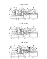
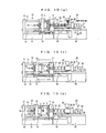
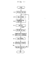
- the injection molding is performed in such a manner as shown in FIGS. 9(a) to 9(c), 10(a) to 10(c) and 11.
- the pressure control is performed in such a manner as described below.
- pressure instruction values P1 and P2 which are target values of the pressure (resin pressure) in the space between the metal molds are set.
- the pressure instruction value P1 is utilized for regulating so that the pressure in the space between the metal molds does not excessively rise upon the velocity control and for performing changeover from the velocity control to the pressure control.
- the other pressure instruction value P2 is utilized upon the pressure control.
- a changeover section 75 based on a V/P changeover signal, the pressure instruction value P1 is selected upon the velocity control (upon V control), but the pressure instruction P2 is selected upon the pressure control (upon-P control).
- a deviation (Pr - P) between the selected pressure instruction value P1 or P2 (hereinafter referred to as Pr) and a pressure detection value P which is a found value of the pressure in the space between the metal molds is calculated (adder 76), and a motor instruction value (current instruction value) is set based on the deviation (Pr - P) by a pressure control section 77 and is outputted.
- the detected force and the preset value of the force to be applied to the resin are compared with each other, and the velocity target value is determined in response to a difference between them. Then, the velocity feedback control is performed so that the actual velocity may be equal to the determined velocity target value to control the operation of the electric motor. Consequently, by performing such pressure control as to make the force applied to the resin and the preset value coincide with each other, dwelling can be performed appropriately and the shrinkage by cooling after the resin filling can be corrected appropriately.
- decreasing correction for the velocity target value for the injection screw in response to the force detection value is not performed until the position detection values approaches a value within a predetermined distance to the predetermined position after the velocity control is started, but decreasing correction for the velocity target value for the injection screw is performed in response to the force detection value on condition that the position detection value comes within the predetermined distance to the predetermined position.
- the pressure applied to the resin material in the metal mold is used as the force applied to the resin material, and, upon the velocity control, a value obtained by multiplying a detection value of the pressure applied to the resin material by a pressure proportional gain is subtracted from a value obtained by multiplying a deviation between a position instruction value for the injection screw and the position detection value by a position proportional gain and a resulting value of the subtraction is used as the velocity target value, but, upon the pressure control, a value determined based on a deviation between a pressure instruction value corresponding to the force target value and the pressure detection value is used as the velocity target value.
- the injection apparatus 20 includes an injection cylinder 22 including a nozzle 21, an injection screw 23 inserted for back and forth movement and rotation in the injection cylinder 22, a heater 24 for heating the raw resin 3 in the injection cylinder 22, a table (driving apparatus table) 25 secured to a base 32, a fixed frame 26 secured to the table 25 for supporting the injection cylinder 22 thereon, a movable frame 27 mounted for movement on the table 25 and having the injection screw 23 coupled thereto, a screw rotating motor 28 provided on the movable frame 27 for driving the injection screw 23 to rotate, an injection screw moving mechanism (referred to also as driving apparatus) 29 provided between the fixed frame 26 and the movable frame 27 for moving the injection screw 23 in an axial direction together with the movable frame 27, and a hopper 30 for supplying the raw resin 3 into the injection cylinder 22.
- driving apparatus driving apparatus
- the motor 29A is controlled by feedback control both in the velocity control and the pressure control. Also in the pressure control, a velocity target value is set and the motor 29A is velocity controlled with the velocity target value to feed back the velocity or the pressure of the injection screw 23 to effect control although this is naturally applied to the velocity control.
- the velocity detection value V is subtracted from the velocity target value U by the adder 58 to calculate a velocity deviation (U - V), and the velocity deviation (U - V) is converted into a motor instruction value (current instruction value) by the velocity control section (motor instruction value setting section) 59.
- the motor 29A is controlled with the motor instruction value (current instruction value) so that the velocity (detection value) thereof may be equal to the target value.
- the velocity control system in the present embodiment uses a velocity instruction value Vr and a velocity detection value V while the velocity control system in the first embodiment uses the position instruction value Xr and the position detection value X.
- the velocity control system is a combination of that in the first embodiment and that in the second embodiment.
- the electric injection molder and the injection velocity and injection pressure controlling method for an electric injection molder as the fifth embodiment of the present invention is configured in such a manner as described above, in addition to operation and effects similar to those of the first to fourth embodiments, changeover from the velocity control to the pressure control can be performed further smoothly because, due to the correction coefficient ⁇ , although the amount of the decreasing correction is small when the decreasing correction is started, the decreasing correction is increased gradually as the position of the injection screw 23 approaches the V/P changeover position.
Landscapes
- Engineering & Computer Science (AREA)
- Manufacturing & Machinery (AREA)
- Mechanical Engineering (AREA)
- Injection Moulding Of Plastics Or The Like (AREA)
Abstract
Description
Corresponding to the first embodiment:
Claims (14)
- An electric injecting molder wherein an injection screw (23) disposed in an injection cylinder (22) is driven to move in forward and backward directions by an electric motor (29A) to inject resin material (3) in said injection cylinder (22) into a metal mold (1, 2) to fill said metal mold (1, 2), characterized in that it comprises
control means (50A to 50C) for velocity-controlling said electric motor (29A) when the resin material (3) is filled into said metal mold (1, 2) but pressure-controlling said electric motor (29A) when the resin material (3) is replenished for shrinkage of the resin after the resin material (3) is filled,
position detection means for detecting or estimating the position of said injection screw (23) in the forward and backward direction,
velocity detect ion means for detecting or estimating the velocity of said injection screw (23) ) in the forward and backward direction, and
force detection means (63a to 63d) for detecting or estimating the force applied to the resin material (3) in said metal mold (1, 2), and that said control means (50A to 50C)
performs changeover from the velocity control to the pressure control after a position detection value from said position detection means reaches a predetermined position set in advance, and
corrects, at least before the changeover from the velocity control to the pressure control upon the velocity control, a velocity target value for said injection screw (23) in response to a force detection value from said force detection means (63a to 63d) so that the velocity target value for said injection screw (23) may decrease as the force detection value increases to perform velocity feedback control of said electric motor (29A) so that the velocity detection value from said velocity detection means may be equal to the velocity target value, but
determines, upon the pressure control, the velocity target value in response to a difference between the force detection value and a force target value to be applied to the resin material (3) and velocity feedback controls said electric motor (29A) so that the velocity detection value may be equal to the determined velocity target value to perform control so that the force detection value and the force target value may coincide with each other. - An electric injection molder as set forth in claim 1, characterized in that .
said control means (50A to 50C) does not perform, upon the velocity control, decreasing correction for the velocity target value for said injection screw (23) in response to the force detection value until the position detection values approaches a value within a predetermined distance to the predetermined position after the velocity control is started, but performs decreasing correction for the velocity target value for said injection screw (23) in response to the force detection value on condition that the position detection value comes within the predetermined distance to the predetermined position. - An electric injection molder as set forth in claim 2, characterized in that,
when said control means (50A to 50C) performs decreasing correction of the velocity target value for said injection screw (23) in response to the force detection value, said control means (50A to 50C) multiplies a decreasing correction amount by a coefficient which gradually increases from 0 to 1 so that the decreasing correction amount may increase in response to the force detection value as the position detection value approaches the predetermined position. - An electric injection molder as set forth in claim 2, characterized in that the predetermined distance is determined by arithmetic operation based on the velocity target value and the force detection value at the current point of time.
- An electronic injection molder as set forth in claim 1, characterized in that
it comprises, as said force detection means, pressure detection means (63a to 63d) for detecting or estimating the pressure applied to the resin material (3) in said metal mold (1, 2), and that said control means (50A)
subtracts, upon the velocity control, a value obtained by multiplying a pressure detection value from said force detection means (63a to 63d) by a pressure proportional gain from a value obtained by multiplying a deviation between a position instruction value for said injection screw (23) and the position detection value from said position detection means by a position proportional gain and uses a resulting value of the subtraction as the velocity target value, but
uses, upon the pressure control, a value determined based on a deviation between a pressure instruction value corresponding to the force target value and the pressure detection value from said pressure detection means (63a to 63d) as the velocity target value. - An electronic injection molder as set forth in claim 1, characterized in that
it comprises, as said force detection means, force detection means (63a to 63d) for detecting or estimating the pressure applied to the resin material (3) in said metal mold (1, 2), and that said control means (50B)
subtracts, upon the velocity control, a value obtained by multiplying a pressure detection value from said pressure detection means (63a to 63d) by a pressure proportional gain from a value obtained by multiplying a deviation between a velocity instruction value for said injection screw (23) and the velocity detection value from said velocity detection means by a velocity proportional gain and uses a resulting value of the subtraction as the velocity target value, but
uses, upon the pressure control, a value determined based on a deviation between a pressure instruction value corresponding to the force target value and the pressure detection value from said pressure detection means (63a to 63d) as the velocity target value. - An electric injection molder as set forth in claim 1, characterized in that
it comprises, as said force detection means, pressure detection means (63a to 63d) for detecting or estimating the pressure applied to the resin material (3) in said metal mold (1, 2), and that said control means (50C)
adds, upon the velocity control, a value obtained by multiplying a deviation between a position instruction value for said injection screw (23) and the position detection value from said position detection means by a position proportional gain and a value obtained by multiplying a deviation between a velocity instruction value for said injection screw (23) and the velocity detection value from said velocity detection means by a velocity proportional gain, subtracts a value obtained by multiplying a pressure detection value from said pressure detection means (63a to 63d) by a pressure proportional gain from a resulting value of the addition and uses a resulting value of the subtraction as the velocity target value, but
uses, upon the pressure control, a value determined based on a deviation between a pressure instruction value corresponding to the force target value and the pressure detection value from said pressure detection means (63a to 63d) as the velocity target value. - An injection velocity and injection pressure controlling method for an electric injecting molder wherein, when an injection screw (23) disposed in an injection cylinder (22) is driven to move in forward and backward directions by an electric motor (29A) to inject resin material (3) in said injection cylinder (22) into a metal mold (1, 2) to fill said metal mold (1, 2), said electric motor (29A) is first velocity-controlled to fill the resin material (3) into said metal mold (1, 2) and, after the resin material (3) is filled, said electric motor (29A) is pressure-controlled to replenish the resin material (3) for shrinkage of the resin, characterized in that,
at least before changeover from the velocity control to the pressure control upon the velocity control, a velocity target value for said injection screw (23) is corrected in response to a detection value of force applied to the resin material (3) so that the velocity target value for said injection screw (23) may decrease as the force detection value increases to perform velocity feedback control of said electric motor (29A) so that a detection value of the velocity of said injection screw (23) may be equal to the velocity target value, and
changeover from the velocity control to the pressure control is performed after the position of said injection screw (23) in the forward and backward direction reaches a predetermined position set in advance, but
upon the pressure control, the velocity target value is determined in response to a difference between the force detection value and a force target value to be applied to the resin material (3) and said electric motor (29A) is velocity feedback controlled so that the velocity detection value may be equal to the determined velocity target value to perform control so that the force detection value and the force target value may coincide with each other. - An injection velocity and injection pressure controlling method for an electric injection molder as set forth in claim 8, characterized in that,
upon the velocity control, decreasing correction for the velocity target value for said injection screw (23) in response to the force detection value is not performed until the position detection values approaches a value within a predetermined distance to the predetermined position after the velocity control is started, but decreasing correction for the velocity target value for said injection screw (23) is performed in response to the force detection value on condition that the position detection value comes within the predetermined distance to the predetermined position. - An injection velocity and injection pressure controlling method for an electric injection molder as set forth in claim 9, characterized in that,
when decreasing correction of the velocity target value for said injection screw (23) is performed in response to the force detection value, a decreasing correction amount is multiplied by a coefficient which gradually increases from 0 to 1 so that the decreasing correction amount may increase in response to the force detection value as the position detection value approaches the predetermined position. - An injection velocity and injection pressure controlling method for an electric injection molder as set forth in claim 9, characterized in that the predetermined distance is determined by arithmetic operation based on the velocity target value and the force detection value at the current point of time.
- An injection velocity and injection pressure controlling method for an electronic injection molder as set forth in claim 8, characterized in that
the pressure applied to the resin material (3) in said metal mold (1, 2) is used as the force applied to the resin material (3), and that,
upon the velocity control, a value obtained by multiplying a detection value of the pressure applied to the resin material (3) by a pressure proportional gain is subtracted from a value obtained by multiplying a deviation between a position instruction value for said injection screw (23) and the position detection value by a position proportional gain and a resulting value of the subtraction is used as the velocity target value, but,
upon the pressure control, a value determined based on a deviation between a pressure instruction value corresponding to the force target value and the pressure detection value is used as the velocity target value. - An injection velocity and injection pressure controlling method for an electronic injection molder as set forth in claim 8, characterized in that
the pressure applied to the resin material (3) in said metal mold (1, 2) is used as the force applied to the resin material (3), and that,
upon the velocity control, a value obtained by multiplying a pressure detection value by a pressure proportional gain is subtracted from a value obtained by multiplying a deviation between a velocity instruction value for said injection screw (23) and the velocity detection value by a velocity proportional gain and a resulting value of the subtraction is used as the velocity target value, but,
upon the pressure control, a value determined based on a deviation between a pressure instruction value and the pressure detection value is used as the velocity target value. - An injection velocity and injection pressure controlling method for an electric extrusion molder as set forth in claim 8, characterized in that
the pressure applied to the resin material (3) in said metal mold (1, 2) is used as the force applied to the resin material (3), and that,
upon the velocity control, a value obtained by multiplying a deviation between a position instruction value for said injection screw (23) and the position detection value by a position proportional gain and a value obtained by multiplying a deviation between a velocity instruction value for said injection screw (23) and the velocity detection value by a velocity proportional gain are added, and a value obtained by multiplying a detection value of the force applied to the resin material (3) by a pressure proportional gain is subtracted from a resulting value of the addition, and then, a resulting value of the subtraction is used as the velocity target value, but,
upon the pressure control, a value determined based on a deviation between a pressure instruction value corresponding to a target value of the force to be applied to the resin material (3) and the pressure detection value is used as the velocity target value.
Applications Claiming Priority (5)
| Application Number | Priority Date | Filing Date | Title |
|---|---|---|---|
| JP2000332869 | 2000-10-31 | ||
| JP2000332869 | 2000-10-31 | ||
| JP2001086052 | 2001-03-23 | ||
| JP2001086052A JP4459467B2 (en) | 2000-10-31 | 2001-03-23 | Electric injection molding machine and injection speed / injection pressure control method of electric injection molding machine |
| PCT/JP2001/009508 WO2002036325A1 (en) | 2000-10-31 | 2001-10-30 | Electric injection molding machine and method of controlling injection speed and injection pressure of electric injection molding machine |
Publications (3)
| Publication Number | Publication Date |
|---|---|
| EP1344623A1 true EP1344623A1 (en) | 2003-09-17 |
| EP1344623A4 EP1344623A4 (en) | 2008-05-14 |
| EP1344623B1 EP1344623B1 (en) | 2009-04-29 |
Family
ID=26603159
Family Applications (1)
| Application Number | Title | Priority Date | Filing Date |
|---|---|---|---|
| EP01978948A Expired - Lifetime EP1344623B1 (en) | 2000-10-31 | 2001-10-30 | Electric injection molding machine and method of controlling injection speed and injection pressure of electric injection molding machine |
Country Status (8)
| Country | Link |
|---|---|
| US (1) | US6854967B2 (en) |
| EP (1) | EP1344623B1 (en) |
| JP (1) | JP4459467B2 (en) |
| CN (1) | CN1233519C (en) |
| CA (1) | CA2396544C (en) |
| DE (1) | DE60138569D1 (en) |
| TW (1) | TWI229031B (en) |
| WO (1) | WO2002036325A1 (en) |
Cited By (1)
| Publication number | Priority date | Publication date | Assignee | Title |
|---|---|---|---|---|
| DE202011000322U1 (en) | 2011-02-11 | 2012-05-16 | MBM Maschinenbau Mühldorf GmbH | injection molding |
Families Citing this family (23)
| Publication number | Priority date | Publication date | Assignee | Title |
|---|---|---|---|---|
| US7008202B2 (en) * | 2001-03-08 | 2006-03-07 | The Japan Steel Works, Ltd. | Method and apparatus for forming thermoplastic resin foam |
| CN100493883C (en) * | 2002-12-30 | 2009-06-03 | 财团法人工业技术研究院 | Injection speed-pressure switching and pressure maintaining control device and method for electric injection molding machine |
| TWI235706B (en) * | 2003-04-07 | 2005-07-11 | Sumitomo Heavy Industries | Method of controlling injection molding machine |
| US7648669B2 (en) * | 2004-11-30 | 2010-01-19 | Bemis Manufacturing Company | Injection-molding system and method |
| JP4168036B2 (en) * | 2005-02-25 | 2008-10-22 | ファナック株式会社 | Pressure abnormality detection device for injection molding machine |
| CN100450746C (en) * | 2005-03-11 | 2009-01-14 | 华南理工大学 | Feedback dynamic mixing extrusion method and equipment along the material process |
| US20080085334A1 (en) * | 2006-10-10 | 2008-04-10 | Husky Injection Molding Systems Ltd. | Hot Runner System Sensor |
| JP4976888B2 (en) * | 2007-03-06 | 2012-07-18 | ソニー株式会社 | Injection control device |
| US7643900B2 (en) | 2007-08-13 | 2010-01-05 | Husky Injection Molding Systems Ltd. | Method of controlling a screw in a two-stage injection unit and a system for implementing the method |
| TW200909184A (en) * | 2007-08-17 | 2009-03-01 | Nat Univ Chung Cheng | Method of sensing melt-front position and velocity |
| US8033808B2 (en) * | 2007-08-24 | 2011-10-11 | Delta Pt, Llc | Pressure compensating molding system |
| TWI416292B (en) * | 2008-04-25 | 2013-11-21 | Chi Mei Comm Systems Inc | System and method for preventing overshoot of a machine |
| JP5092927B2 (en) * | 2008-06-20 | 2012-12-05 | ソニー株式会社 | INJECTION MOLDING CONTROL METHOD AND INJECTION MOLDING CONTROL DEVICE |
| JP5998009B2 (en) * | 2011-12-12 | 2016-09-28 | 東芝機械株式会社 | Molding machine control device and molding machine control method |
| US10046501B2 (en) * | 2013-03-13 | 2018-08-14 | Chevron Phillips Chemical Company Lp | System and method for polymer extrusion |
| JP6005569B2 (en) * | 2013-03-25 | 2016-10-12 | 住友重機械工業株式会社 | Injection molding machine |
| JP6133250B2 (en) * | 2014-09-18 | 2017-05-24 | 本田技研工業株式会社 | Method and apparatus for molding fiber reinforced resin molded product |
| JP6367079B2 (en) * | 2014-10-22 | 2018-08-01 | 住友重機械工業株式会社 | Injection molding machine |
| JP6169633B2 (en) | 2015-03-04 | 2017-07-26 | ファナック株式会社 | Pressure control device for injection molding machine |
| KR102181653B1 (en) * | 2015-06-25 | 2020-11-23 | 엘에스엠트론 주식회사 | Injection molding machine |
| JP6923587B2 (en) * | 2019-03-28 | 2021-08-18 | ファナック株式会社 | Servo motor controller |
| CN112297352A (en) * | 2020-10-10 | 2021-02-02 | 海宁市天翼龙电器有限公司 | Injection molding raw material injection speed detection equipment for injection molding machine |
| CN112917855B (en) * | 2021-01-22 | 2022-08-30 | 杭州电子科技大学 | Flexible switching control method and device of injection molding machine |
Family Cites Families (19)
| Publication number | Priority date | Publication date | Assignee | Title |
|---|---|---|---|---|
| JPS62207622A (en) * | 1986-03-07 | 1987-09-12 | Japan Steel Works Ltd:The | Injection controlling of motor-driven injection machine |
| JPH0356887A (en) | 1989-07-26 | 1991-03-12 | Mitsubishi Electric Corp | Fluorescent plate type monitor for charge particle device |
| JPH0444891A (en) | 1990-06-11 | 1992-02-14 | Hitachi Maxell Ltd | Thermal transfer element |
| JPH0450172A (en) | 1990-06-18 | 1992-02-19 | Kawasaki Steel Corp | Preparation of highly conductive aln sintered |
| JPH04347616A (en) * | 1991-05-27 | 1992-12-02 | Mitsubishi Materials Corp | Molding machine |
| JPH0628253A (en) | 1992-03-24 | 1994-02-04 | Nec Corp | Central processor |
| JP2660636B2 (en) | 1992-04-17 | 1997-10-08 | ファナック株式会社 | Injection control method for injection molding machine |
| JP3056887B2 (en) * | 1992-07-09 | 2000-06-26 | 本田技研工業株式会社 | Drive device of drawbar in spindle device |
| BR9300315A (en) | 1993-02-03 | 1994-10-04 | Johnson & Johnson Ind Com | Toothbrush. |
| JP2595450B2 (en) * | 1993-09-08 | 1997-04-02 | 日精樹脂工業株式会社 | Method and apparatus for detecting abnormality of hydraulic system in molding machine |
| JP2779759B2 (en) | 1993-12-15 | 1998-07-23 | 日精樹脂工業株式会社 | Injection control method for injection molding machine |
| JP3166632B2 (en) * | 1996-10-09 | 2001-05-14 | 株式会社新潟鉄工所 | Control device and control method for electric injection molding machine |
| JP2921754B2 (en) | 1997-05-28 | 1999-07-19 | ファナック株式会社 | Drive control device for servo motor |
| JP2866361B2 (en) | 1997-05-28 | 1999-03-08 | ファナック株式会社 | Injection mechanism drive |
| JP3250180B2 (en) * | 1998-06-17 | 2002-01-28 | 住友重機械工業株式会社 | Depressurization method in plasticization / metering process of electric injection molding machine |
| DE19847682C1 (en) * | 1998-10-15 | 2000-03-30 | Siemens Ag | Changeover controller for pressure injection molding machine, generates control signal corrections preventing undesirable transients in melt feedrate and pressure |
| JP3164570B2 (en) * | 1999-09-16 | 2001-05-08 | ファナック株式会社 | Overload detection device for screw or screw head |
| JP3619431B2 (en) * | 2000-07-18 | 2005-02-09 | 日精樹脂工業株式会社 | Control method of injection molding machine |
| JP4050172B2 (en) * | 2003-03-27 | 2008-02-20 | 大成建設株式会社 | Evaluation method for soundness of concrete piles |
-
2001
- 2001-03-23 JP JP2001086052A patent/JP4459467B2/en not_active Expired - Fee Related
- 2001-10-30 CA CA002396544A patent/CA2396544C/en not_active Expired - Fee Related
- 2001-10-30 WO PCT/JP2001/009508 patent/WO2002036325A1/en not_active Ceased
- 2001-10-30 EP EP01978948A patent/EP1344623B1/en not_active Expired - Lifetime
- 2001-10-30 CN CN01803354.7A patent/CN1233519C/en not_active Expired - Fee Related
- 2001-10-30 DE DE60138569T patent/DE60138569D1/en not_active Expired - Lifetime
- 2001-10-30 US US10/168,866 patent/US6854967B2/en not_active Expired - Fee Related
- 2001-10-31 TW TW090127026A patent/TWI229031B/en not_active IP Right Cessation
Cited By (1)
| Publication number | Priority date | Publication date | Assignee | Title |
|---|---|---|---|---|
| DE202011000322U1 (en) | 2011-02-11 | 2012-05-16 | MBM Maschinenbau Mühldorf GmbH | injection molding |
Also Published As
| Publication number | Publication date |
|---|---|
| CN1233519C (en) | 2005-12-28 |
| US20020192322A1 (en) | 2002-12-19 |
| CA2396544C (en) | 2006-01-24 |
| JP4459467B2 (en) | 2010-04-28 |
| US6854967B2 (en) | 2005-02-15 |
| CA2396544A1 (en) | 2002-05-10 |
| TWI229031B (en) | 2005-03-11 |
| JP2002200657A (en) | 2002-07-16 |
| DE60138569D1 (en) | 2009-06-10 |
| WO2002036325A1 (en) | 2002-05-10 |
| EP1344623A4 (en) | 2008-05-14 |
| EP1344623B1 (en) | 2009-04-29 |
| CN1394162A (en) | 2003-01-29 |
Similar Documents
| Publication | Publication Date | Title |
|---|---|---|
| EP1344623B1 (en) | Electric injection molding machine and method of controlling injection speed and injection pressure of electric injection molding machine | |
| US6340439B1 (en) | Depressurization method in plasticization and metering process for a motor-driven injection molding machine | |
| US20090315205A1 (en) | Control method of injection molding and control apparatus of injection molding | |
| US20130147078A1 (en) | Molding machine controlling apparatus and method of controlling molding machine | |
| US20090057938A1 (en) | Closed Loop Control for an Injection Unit | |
| EP1418039B1 (en) | Metering method and control apparatus for injection molding machine | |
| US5380181A (en) | Control device for an electric injection molding machine | |
| US7344369B2 (en) | Controller for injection molding machine | |
| EP0582987A1 (en) | Control unit with gain changing means responsive to operating conditions | |
| US6663804B2 (en) | Method and apparatus for controlling injection molding machine capable of reducing variations in weight of molded products | |
| EP1072387B1 (en) | Method and apparatus for adjusting zero point of a pressure sensor of an injection apparatus | |
| US5232714A (en) | In-line screw type injection molding machine | |
| JP4627250B2 (en) | Control method of injection molding machine | |
| EP0965430B1 (en) | Method for controlling drive of screw in injection molding machine | |
| JP4068799B2 (en) | Electric injection molding machine and injection molding method using electric injection molding machine | |
| JP4206094B2 (en) | Electric injection molding machine and injection molding method using electric injection molding machine | |
| JP3648083B2 (en) | Control method of injection molding machine | |
| US20020005598A1 (en) | Method of controlling the screw of injection molding machine | |
| JP4002563B2 (en) | Pressure feedback control system and control method thereof | |
| JP3686771B2 (en) | Injection molding machine | |
| JP4974001B2 (en) | Injection molding machine and molding method | |
| JP3052187B2 (en) | Back pressure control method of electric injection molding machine | |
| JPS6158286B2 (en) | ||
| JP2009090613A (en) | Injection molding machine and molding method |
Legal Events
| Date | Code | Title | Description |
|---|---|---|---|
| PUAI | Public reference made under article 153(3) epc to a published international application that has entered the european phase |
Free format text: ORIGINAL CODE: 0009012 |
|
| 17P | Request for examination filed |
Effective date: 20020717 |
|
| AK | Designated contracting states |
Kind code of ref document: A1 Designated state(s): AT BE CH CY DE DK ES FI FR GB GR IE IT LI LU MC NL PT SE TR |
|
| RBV | Designated contracting states (corrected) |
Designated state(s): AT BE DE IT |
|
| A4 | Supplementary search report drawn up and despatched |
Effective date: 20080411 |
|
| GRAP | Despatch of communication of intention to grant a patent |
Free format text: ORIGINAL CODE: EPIDOSNIGR1 |
|
| RBV | Designated contracting states (corrected) |
Designated state(s): DE IT |
|
| GRAS | Grant fee paid |
Free format text: ORIGINAL CODE: EPIDOSNIGR3 |
|
| GRAA | (expected) grant |
Free format text: ORIGINAL CODE: 0009210 |
|
| AK | Designated contracting states |
Kind code of ref document: B1 Designated state(s): DE IT |
|
| REF | Corresponds to: |
Ref document number: 60138569 Country of ref document: DE Date of ref document: 20090610 Kind code of ref document: P |
|
| PLBE | No opposition filed within time limit |
Free format text: ORIGINAL CODE: 0009261 |
|
| STAA | Information on the status of an ep patent application or granted ep patent |
Free format text: STATUS: NO OPPOSITION FILED WITHIN TIME LIMIT |
|
| 26N | No opposition filed |
Effective date: 20100201 |
|
| PGFP | Annual fee paid to national office [announced via postgrant information from national office to epo] |
Ref country code: IT Payment date: 20141017 Year of fee payment: 14 |
|
| PG25 | Lapsed in a contracting state [announced via postgrant information from national office to epo] |
Ref country code: IT Free format text: LAPSE BECAUSE OF NON-PAYMENT OF DUE FEES Effective date: 20151030 |
|
| REG | Reference to a national code |
Ref country code: DE Ref legal event code: R082 Ref document number: 60138569 Country of ref document: DE Representative=s name: HOFFMANN - EITLE PATENT- UND RECHTSANWAELTE PA, DE Ref country code: DE Ref legal event code: R081 Ref document number: 60138569 Country of ref document: DE Owner name: U-MHI PLATECH CO., LTD., NAGOYA-SHI, JP Free format text: FORMER OWNER: MITSUBISHI HEAVY INDUSTRIES, LTD., TOKIO/TOKYO, JP |
|
| PGFP | Annual fee paid to national office [announced via postgrant information from national office to epo] |
Ref country code: DE Payment date: 20191015 Year of fee payment: 19 |
|
| REG | Reference to a national code |
Ref country code: DE Ref legal event code: R119 Ref document number: 60138569 Country of ref document: DE |
|
| PG25 | Lapsed in a contracting state [announced via postgrant information from national office to epo] |
Ref country code: DE Free format text: LAPSE BECAUSE OF NON-PAYMENT OF DUE FEES Effective date: 20210501 |