EP1344603B1 - Motion unit of a machine tool and machine tool with such a motion unit - Google Patents
Motion unit of a machine tool and machine tool with such a motion unit Download PDFInfo
- Publication number
- EP1344603B1 EP1344603B1 EP02005488A EP02005488A EP1344603B1 EP 1344603 B1 EP1344603 B1 EP 1344603B1 EP 02005488 A EP02005488 A EP 02005488A EP 02005488 A EP02005488 A EP 02005488A EP 1344603 B1 EP1344603 B1 EP 1344603B1
- Authority
- EP
- European Patent Office
- Prior art keywords
- guide
- motion
- guide units
- unit according
- motion unit
- Prior art date
- Legal status (The legal status is an assumption and is not a legal conclusion. Google has not performed a legal analysis and makes no representation as to the accuracy of the status listed.)
- Expired - Lifetime
Links
Images


Classifications
-
- B—PERFORMING OPERATIONS; TRANSPORTING
- B23—MACHINE TOOLS; METAL-WORKING NOT OTHERWISE PROVIDED FOR
- B23Q—DETAILS, COMPONENTS, OR ACCESSORIES FOR MACHINE TOOLS, e.g. ARRANGEMENTS FOR COPYING OR CONTROLLING; MACHINE TOOLS IN GENERAL CHARACTERISED BY THE CONSTRUCTION OF PARTICULAR DETAILS OR COMPONENTS; COMBINATIONS OR ASSOCIATIONS OF METAL-WORKING MACHINES, NOT DIRECTED TO A PARTICULAR RESULT
- B23Q5/00—Driving or feeding mechanisms; Control arrangements therefor
- B23Q5/22—Feeding members carrying tools or work
- B23Q5/34—Feeding other members supporting tools or work, e.g. saddles, tool-slides, through mechanical transmission
- B23Q5/38—Feeding other members supporting tools or work, e.g. saddles, tool-slides, through mechanical transmission feeding continuously
- B23Q5/385—Feeding other members supporting tools or work, e.g. saddles, tool-slides, through mechanical transmission feeding continuously using a gear and rack mechanism or a friction wheel co-operating with a rail
-
- B—PERFORMING OPERATIONS; TRANSPORTING
- B21—MECHANICAL METAL-WORKING WITHOUT ESSENTIALLY REMOVING MATERIAL; PUNCHING METAL
- B21D—WORKING OR PROCESSING OF SHEET METAL OR METAL TUBES, RODS OR PROFILES WITHOUT ESSENTIALLY REMOVING MATERIAL; PUNCHING METAL
- B21D28/00—Shaping by press-cutting; Perforating
- B21D28/02—Punching blanks or articles with or without obtaining scrap; Notching
-
- B—PERFORMING OPERATIONS; TRANSPORTING
- B23—MACHINE TOOLS; METAL-WORKING NOT OTHERWISE PROVIDED FOR
- B23Q—DETAILS, COMPONENTS, OR ACCESSORIES FOR MACHINE TOOLS, e.g. ARRANGEMENTS FOR COPYING OR CONTROLLING; MACHINE TOOLS IN GENERAL CHARACTERISED BY THE CONSTRUCTION OF PARTICULAR DETAILS OR COMPONENTS; COMBINATIONS OR ASSOCIATIONS OF METAL-WORKING MACHINES, NOT DIRECTED TO A PARTICULAR RESULT
- B23Q3/00—Devices holding, supporting, or positioning work or tools, of a kind normally removable from the machine
- B23Q3/155—Arrangements for automatic insertion or removal of tools, e.g. combined with manual handling
- B23Q3/1556—Arrangements for automatic insertion or removal of tools, e.g. combined with manual handling of non-rotary tools
- B23Q3/15566—Arrangements for automatic insertion or removal of tools, e.g. combined with manual handling of non-rotary tools the tool being inserted in a tool holder directly from a storage device, i.e. without using transfer devices
-
- B—PERFORMING OPERATIONS; TRANSPORTING
- B23—MACHINE TOOLS; METAL-WORKING NOT OTHERWISE PROVIDED FOR
- B23Q—DETAILS, COMPONENTS, OR ACCESSORIES FOR MACHINE TOOLS, e.g. ARRANGEMENTS FOR COPYING OR CONTROLLING; MACHINE TOOLS IN GENERAL CHARACTERISED BY THE CONSTRUCTION OF PARTICULAR DETAILS OR COMPONENTS; COMBINATIONS OR ASSOCIATIONS OF METAL-WORKING MACHINES, NOT DIRECTED TO A PARTICULAR RESULT
- B23Q7/00—Arrangements for handling work specially combined with or arranged in, or specially adapted for use in connection with, machine tools, e.g. for conveying, loading, positioning, discharging, sorting
- B23Q7/04—Arrangements for handling work specially combined with or arranged in, or specially adapted for use in connection with, machine tools, e.g. for conveying, loading, positioning, discharging, sorting by means of grippers
- B23Q7/046—Handling workpieces or tools
-
- F—MECHANICAL ENGINEERING; LIGHTING; HEATING; WEAPONS; BLASTING
- F16—ENGINEERING ELEMENTS AND UNITS; GENERAL MEASURES FOR PRODUCING AND MAINTAINING EFFECTIVE FUNCTIONING OF MACHINES OR INSTALLATIONS; THERMAL INSULATION IN GENERAL
- F16H—GEARING
- F16H55/00—Elements with teeth or friction surfaces for conveying motion; Worms, pulleys or sheaves for gearing mechanisms
- F16H55/02—Toothed members; Worms
- F16H55/26—Racks
-
- Y—GENERAL TAGGING OF NEW TECHNOLOGICAL DEVELOPMENTS; GENERAL TAGGING OF CROSS-SECTIONAL TECHNOLOGIES SPANNING OVER SEVERAL SECTIONS OF THE IPC; TECHNICAL SUBJECTS COVERED BY FORMER USPC CROSS-REFERENCE ART COLLECTIONS [XRACs] AND DIGESTS
- Y10—TECHNICAL SUBJECTS COVERED BY FORMER USPC
- Y10T—TECHNICAL SUBJECTS COVERED BY FORMER US CLASSIFICATION
- Y10T83/00—Cutting
- Y10T83/869—Means to drive or to guide tool
Definitions
- the invention relates to a movement unit on machine tools, with at least one drive and at least one drive associated motion guide, wherein the drive at least a rack and at least one meshing drive pinion and the motion guide at least one support structure and a plurality of guide units comprising guided the support structure and by means of the drive jointly are movable.
- the invention further relates a machine tool with such a movement unit.
- Prior art machine of the type "TC 5000 R”, produced by the Company “TRUMPF”, 71254 Ditzingen (Germany) is offered and in the distributed by the company “TRUMPF”, post-published Brochure entitled “TRUMATIC 5000 ROTATION” is.
- the previously known machine has a movement unit in the form of a coordinate guide. By means of the coordinate guidance be compared to a punching station of the machine plates for processing and editing tools to change and move or positioned. The workpiece and the tool movement takes place doing so in a horizontal plane passing through x and y coordinate axes is defined. For each of these axis directions is provided a separate movement guide.
- guide units In the direction of the x-axis are guide units with clamps for the to be processed Sheets and with cassettes for holding processing tools movably guided on a mounting rail.
- the movement guide for the x-direction on the machine frame In the direction of the y-axis can the movement guide for the x-direction on the machine frame be moved.
- guidance units are provided, which is connected to the motion control for the x-axis are as well as mounting rails of the machine frame, which there in Y direction and along which the leadership units move for the y direction.
- To drive the guide units for the x-direction and for driving the guide units for the y-direction each serves a rack drive with a stationary Drive pinion and with a attached to the relevant leadership units and with the Guiding units of shared rack.
- the present invention aims.
- the guide units are not only Part of the movement in question but beyond also of the drive provided for this purpose. Subsequently reduced the number of times required to move the guide units Components. The overall arrangement becomes compact, their own weight or their own weight is reduced to one Minimum.
- the management units results from the or the associated drive pinion a very short and in terms of occurring Strains simply optimizable way for the flow of into the Guide units to be initiated driving force. All in all can be with the movement unit according to the invention and with the machine tool according to the invention movements with high Realize speed while maintaining high accuracy.
- Claim 2 describes a Erfindungsbauart, which is by a particularly simple structural design as well by a particularly effective transmission of the driving force distinguishes the leadership units.
- the gearing sections The rack form completely integral components the relevant leadership units.
- the claims 3, 4, 5 and 6 relate to preferred according to the invention Possibilities for mutual adjustment of the gear sections the rack provided guide units and thus the gearing sections themselves.
- the relevant management units can be found both in their direction of movement as well as transversely defined against each other be fixed.
- Erfindungsbauart according to claim 6 becomes the mutual adjustment of the guide units transverse to the direction of movement of the support structure accepted. Additional Justage Nobel therefore only needed for mutual alignment and fixation of the guide units in the direction of movement.
- the claims 9 and 10 refer to embodiments the movement unit according to the invention, the movement of workpieces and / or of machining tools Serve processing stations of machine tools.
- multi-axis To perform movements, such as in the coordinate guide according to claim 10 is the case and will be for each movement axis guide carriage according to the invention with at least partially integrated gear sections used this results in an accumulation of the advantages according to the invention.
- FIG. 1 has a machine tool in the form of a Punching machine 1 a C-shaped machine frame 2 with a lower frame legs 3 and an upper frame leg. 4 Both frame legs 3, 4 are shown broken off in Fig. 1.
- This punching station is more conventional Type and includes a arranged on the lower frame leg 3 Tool holder for the punching lower tool and a provided on the upper frame leg 4 tool holder for the punching tool.
- a moving unit accommodated in the form of a coordinate guide 5.
- This includes a first movement guide in the form of an x-guide 6 and a second motion guide in the form of a y-guide 7th
- the x-guide 6 has an x-rail 8 as a support structure, in the direction of a first axis of movement, namely the x-axis 9, extends.
- At individual Carriages 10 are claws 11, on other tool cassettes 12 attached.
- the claws 11 are used in conventional Way for holding a workpiece in the form of a sheet 13; the tool cassettes 12 each store as a punching tool 14 formed multi-part machining tool.
- Gear sections 15 provided at the after bottom side facing the carriage 10 with their Wall formed, cut in the example shown case Gear sections 15 provided.
- the toothed portions 15 at the in the direction of the x-axis. 9 successive carriages 10 close in the mentioned direction to each other and form in this way a offset-free rack 16.
- Drive pinion 17 which on the shaft of one of the x-rail. 8 mounted drive motor is seated.
- the drive pinion 17 and the rack 16 and the toothed portions 15 are parts a drive in the form of an x-drive 18, by means of which the guide carriage 10 in the direction of the x-axis 9 on the x-rail 8 can be moved along.
- the x-rail 8 In the direction of the x-axis 9, the x-rail 8 is stationary. In the direction of a second axis of movement, namely the y-axis 19, the x-rail 8 can move by means of the y-guide 7 become.
- a support structure of the y-guide 7 acts the lower Frame legs 3 with attached at its top guide rails 20.
- At the lower frame leg 3 or at the Guide rails 20 are movable along guide units in the form of guide carriage 21.
- a portion of the carriage 21 stores the x-rail 8. All carriages 21 are at one Exterior wall provided with toothing portions 22, the same as the gear portions 15 on the carriage 10 in the relevant car outer wall are cut.
- the gearing sections 22 form a non-offset rack 23.
- a drive pinion 24 which is on the shaft of a stationary drive motor is mounted.
- the components mentioned form a drive in the form of a y-drive 25, by means of which the x-rail 8 is moved in the direction of the y-axis 19 can be.
- Figs. 1 and 3 to 5 indicated are the carriages 10 of the x-guide 6 via a tie rod 26, the carriage 21 of the y-guide 7 via a tie rod 27 connected to each other.
- the tie rod 26 extends in the direction of the x-axis 9, the tie rod 27 in the direction of the y-axis 19.
- the tie rods 26, 27 ensure that the toothing sections 15, 22 in the respective movement direction coherent and thus offset-free Racks 16, 23 form. If necessary, between single carriages 10, 21 to create a uniform Gearing spacers are inserted.
- a contribution for mutual adjustment of the individual guide carriage 10 or the individual carriage 21 also makes their respective Storage on the x-rail 8 or on the lower frame legs 3.
- This storage is transverse to the direction of movement of the carriage 10, 21, ie transverse to the x-axis 9 and the y-axis 19 essentially free of play.
- Carriage 10, 21 On the respective support structure results thus a mutual adjustment of the carriages 10, 21 and thereby an offset freedom of the gear sections 15, 22 formed racks 16, 23 transversely to the x-axis 9 and the y-axis 19.
- connection bar 28 is provided be.
- the connection bar 28 is with the carriage 10 bolted on the outside. Accordingly, according to the FIGS. 9 and 10, a connection bar 29 the previously described Tie rod 27 for coupling the carriage 21 of the y-guide Replace 7.
- FIGS. 10 to 13 Compared to the conditions according to Figs. 5 and 8 modified Types of y-guide 7 are shown in FIGS. 10 to 13 can be seen.
- the drive pinion 24 is pointing to the down Attached end of a motor shaft.
- the cross-sectional shape of guide rails 120 of the lower frame leg 3 Opposite the circumstances after the Fign. 5 and 8 also modified is the cross-sectional shape of guide rails 120 of the lower frame leg 3, which the guide carriage 21 and carriage 221 of the Store y-guide 7 on concave side walls.
- FIGS. 12 and 13 are the carriages 221 of the y-guide 7 with respect to the guide carriage 21 described above modified constructively.
- the carriages 221 in the direction of the y-axis 19 with fits 232 overlapping screwed together. This ensures that in the Guide carriage 221 cut teeth sections 222 a form offset-free, continuous rack 223. evidenced Fig. 12, the toothing portions 222 on lateral Projections of the carriage 221 provided.
- the x-guide 6 can be structurally designed accordingly be. Generally there is the possibility of the different ones Types of x-guide 6 and the y-guide 7 arbitrarily with each other to combine.
- the plate 13 and the punching tools 14th by means of the coordinate guide 5 in the through the x-axis 9 as well the y-axis 19 defined plane with respect to the not shown Processing station moved or positioned.
- the on the x-rail 8 held punching tools 14 can thereby Insert into or out of the tool holders at the punching station remove the tool holders.
- a detailed description can be found in DE-A-38 18 001.
- the plate 13 slides in its movement in the direction of the x-axis 9 on a workpiece table 30, the guide carriage 21, 221 the y-guide 7 is mounted and in the direction of the y-axis 19th is moved.
- Struts 31 provide stiffening of the coordinate guidance 5th
Landscapes
- Engineering & Computer Science (AREA)
- Mechanical Engineering (AREA)
- Machine Tool Units (AREA)
- Automatic Tool Replacement In Machine Tools (AREA)
Abstract
Description
Die Erfindung betrifft eine Bewegungseinheit an Werkzeugmaschinen, mit wenigstens einem Antrieb sowie zumindest einer dem Antrieb zugeordneten Bewegungsführung, wobei der Antrieb zumindest eine Zahnstange sowie zumindest ein damit kämmendes Antriebsritzel und die Bewegungsführung zumindest eine Tragstruktur sowie eine Mehrzahl von Führungseinheiten umfasst, die an der Tragstruktur geführt und mittels des Antriebes gemeinschaftlich bewegbar sind. Die Erfindung betrifft des Weiteren eine Werkzeugmaschine mit einer derartigen Bewegungseinheit.The invention relates to a movement unit on machine tools, with at least one drive and at least one drive associated motion guide, wherein the drive at least a rack and at least one meshing drive pinion and the motion guide at least one support structure and a plurality of guide units comprising guided the support structure and by means of the drive jointly are movable. The invention further relates a machine tool with such a movement unit.
Gattungsbildender Stand der Technik ist die aus praktischer Anschauung vorbekannte Maschine des Typs "TC 5000 R", die von der Firma "TRUMPF", 71254 Ditzingen (Deutschland) angeboten wird und die in dem von der Firma "TRUMPF" verteilten, nachveröffentlichten Prospekt mit dem Titel "TRUMATIC 5000 ROTATION" beschrieben ist. Die vorbekannte Maschine verfügt über eine Bewegungseinheit in Form einer Koordinatenführung. Mittels der Koordinatenführung werden gegenüber einer Stanzstation der Maschine Bleche zur Bearbeitung und Bearbeitungswerkzeuge zum Ein- und Auswechseln bewegt bzw. positioniert. Die Werkstück- sowie die Werkzeugbewegung erfolgt dabei in einer horizontalen Ebene, die durch x- und y-Koordinatenachsen definiert ist. Für jede dieser Achsrichtungen ist eine eigene Bewegungsführung vorgesehen. In Richtung der x-Achse sind Führungseinheiten mit Spannpratzen für die zu bearbeitenden Bleche sowie mit Kassetten zur Aufnahme von Bearbeitungswerkzeugen an einer Tragschiene bewegbar geführt. In Richtung der y-Achse kann die Bewegungsführung für die x-Richtung an dem Maschinengestell verfahren werden. Zu diesem Zweck vorgesehen sind Führungseinheiten, die mit der Bewegungsführung für die x-Achse verbunden sind sowie Tragschienen des Maschinengestells, die dort in y-Richtung verlaufen und entlang derer sich die Führungseinheiten für die y-Richtung bewegen. Zum Antrieb der Führungseinheiten für die x-Richtung sowie zum Antrieb der Führungseinheiten für die y-Richtung dient jeweils ein Zahnstangenantrieb mit einem ortsfesten Antriebsritzel sowie mit einer an den betreffenden Führungseinheiten angebrachten und mit den Führungseinheiten gemeinschaftlich bewegten Zahnstange.Generic prior art is that of practical view Prior art machine of the type "TC 5000 R", produced by the Company "TRUMPF", 71254 Ditzingen (Germany) is offered and in the distributed by the company "TRUMPF", post-published Brochure entitled "TRUMATIC 5000 ROTATION" is. The previously known machine has a movement unit in the form of a coordinate guide. By means of the coordinate guidance be compared to a punching station of the machine plates for processing and editing tools to change and move or positioned. The workpiece and the tool movement takes place doing so in a horizontal plane passing through x and y coordinate axes is defined. For each of these axis directions is provided a separate movement guide. In the direction of the x-axis are guide units with clamps for the to be processed Sheets and with cassettes for holding processing tools movably guided on a mounting rail. In the direction of the y-axis can the movement guide for the x-direction on the machine frame be moved. For this purpose, guidance units are provided, which is connected to the motion control for the x-axis are as well as mounting rails of the machine frame, which there in Y direction and along which the leadership units move for the y direction. To drive the guide units for the x-direction and for driving the guide units for the y-direction each serves a rack drive with a stationary Drive pinion and with a attached to the relevant leadership units and with the Guiding units of shared rack.
Den Stand der Technik konstruktiv zu vereinfachen, hat sich die vorliegende Erfindung zum Ziel gesetzt.To simplify the state of the art constructively, the present invention aims.
Erfindungsgemäß gelöst wird diese Aufgabe durch eine Bewegungseinheit
gemäß Patentanspruch 1 sowie durch eine Werkzeugmaschine
gemäß Patentanspruch 11.This object is achieved according to the invention by a movement unit
according to
Im Sinne der Erfindung sind die Führungseinheiten nicht nur Teil der betreffenden Bewegungsführung sondern darüber hinaus auch des für diese vorgesehenen Antriebes. In der Folge verringert sich die Anzahl der zur Bewegung der Führungseinheiten benötigten Bauteile. Die Gesamtanordnung wird dadurch kompakt, ihre Eigenmasse bzw. ihr Eigengewicht reduziert sich auf ein Minimum. Infolge der unmittelbaren Beaufschlagung der Führungseinheiten durch das oder die zugeordneten Antriebsritzel ergibt sich ein ausgesprochen kurzer und hinsichtlich der auftretenden Belastungen einfach optimierbarer Weg für den Fluss der in die Führungseinheiten einzuleitenden Antriebskraft. Alles in allem lassen sich mit der erfindungsgemäßen Bewegungseinheit sowie mit der erfindungsgemäßen Werkzeugmaschine Bewegungen mit hoher Geschwindigkeit bei gleichzeitig hoher Genauigkeit realisieren. For the purposes of the invention, the guide units are not only Part of the movement in question but beyond also of the drive provided for this purpose. Subsequently reduced the number of times required to move the guide units Components. The overall arrangement becomes compact, their own weight or their own weight is reduced to one Minimum. As a result of the direct admission of the management units results from the or the associated drive pinion a very short and in terms of occurring Strains simply optimizable way for the flow of into the Guide units to be initiated driving force. All in all can be with the movement unit according to the invention and with the machine tool according to the invention movements with high Realize speed while maintaining high accuracy.
Besondere Ausführungsarten der Erfindung ergeben sich aus den
abhängigen Patentansprüchen 2 bis 10.Particular embodiments of the invention will become apparent from the
Patentanspruch 2 beschreibt eine Erfindungsbauart, die sich
durch eine besonders einfache konstruktive Gestaltung sowie
durch eine besonders wirksame Übertragung der Antriebskraft auf
die Führungseinheiten auszeichnet. Die Verzahnungsabschnitte
der Zahnstange bilden dabei vollständig integrale Bestandteile
der betreffenden Führungseinheiten.
Die Patentansprüche 3, 4, 5 und 6 betreffen erfindungsgemäß bevorzugte
Möglichkeiten zur gegenseitigen Justage der mit Verzahnungsabschnitten
der Zahnstange versehenen Führungseinheiten
und somit der Verzahnungsabschnitte selbst. Mittels des Zugankers
nach Patentanspruch 3 und auch mittels der Verbindungsleiste
nach Patentanspruch 4 und der Überlappung nach Patentanspruch
5 können die betreffenden Führungseinheiten sowohl in
ihrer Bewegungsrichtung als auch quer dazu definiert gegeneinander
fixiert werden. Im Falle der Erfindungsbauart gemäß Patentanspruch
6 wird die gegenseitige Justage der Führungseinheiten
quer zu deren Bewegungsrichtung von der Tragstruktur
übernommen. Zusätzlicher Justagemittel bedarf es somit nur noch
zur gegenseitigen Ausrichtung und Fixierung der Führungseinheiten
in Bewegungsrichtung. The
Durch besonders günstige Verhältnisse bei der Übertragung der
Antriebskraft zeichnet sich die in Patentanspruch 7 beschriebene
Ausführungsform der erfindungsgemäßen Bewegungseinheit aus.
Quer zu der Bewegungsrichtung der Führungseinheiten wirksame
Komponenten der Antriebskraft können unter Vermeidung von auf
die Führungseinheiten ausgeübten Kippmomenten in die zugeordnete
Tragstruktur abgeleitet werden.Due to particularly favorable conditions in the transfer of
Driving force is characterized in
Der Einsatz gleichartiger Führungseinheiten, wie er ausweislich
Patentanspruch 8 in Weiterbildung der Erfindung vorgesehen ist,
erlaubt es, einzelne Führungseinheiten beliebig miteinander zu
kombinieren. Werden derartige Führungseinheiten vorgehalten, so
lässt sich beispielsweise ein beschädigungsbedingter Austausch
einer Führungseinheit gegen eine andere Führungseinheit mit minimalem
Aufwand vornehmen. Führungseinheiten mit weiteren Funktionseinrichtungen,
beispielsweise mit Haltevorrichturigen für
Werkstücke oder mit Haltevorrichtungen für Bearbeitungswerkzeuge,
können innerhalb einer Reihe von Führungseinheiten beliebig
umgesetzt werden, ohne dass dadurch das funktionssichere Zusammenwirken
der Verzahnungsabschnitte an den einzelnen Führungseinheiten
beeinträchtigt würde.The use of similar leadership units, as evidenced
Den Patentansprüchen 9 und 10 zu entnehmen sind Ausführungsformen
der erfindungsgemäßen Bewegungseinheit, die zur Bewegung
von Werkstücken und/oder von Bearbeitungswerkzeugen gegenüber
Bearbeitungsstationen von Werkzeugmaschinen dienen. Sind mehrachsige
Bewegungen auszuführen, wie dies etwa bei der Koordinatenführung
nach Patentanspruch 10 der Fall ist und werden für
jede Bewegungsachse erfindungsgemäße Führungswagen mit zumindest
teilweise integrierten Verzahnungsabschnitten verwendet,
so ergibt sich eine Akkumulation der erfindungsgemäßen Vorteile.The
Nachstehend wird die Erfindung anhand beispielhafter schematischer Darstellungen näher erläutert. Es zeigen:
- Fig. 1
- eine stark schematisierte Teildarstellung einer Werkzeugmaschine mit einer Bewegungseinheit mit x-Führung sowie mit y-Führung,
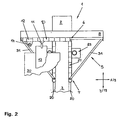
- Fig. 2
- die Werkzeugmaschine nach Fig. 1 in der Draufsicht auf die Bewegungseinheit,
- Fign. 3 und 4
- teilgeschnittene Darstellungen zu der x-Führung nach den Fign. 1 und 2,
- Fig. 5
- eine teilgeschnittene Darstellung zu der y-Führung nach den Fign. 1 und 2,
- Fign. 6 und 7
- Darstellungen entsprechend den Fign. 3 und 4 zu einer zweiten Bauart der x-Führung,
- Fig. 8
- eine Darstellung entsprechend Fig. 5 zu einer zweiten Bauart der y-Führung,
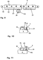
- Fig. 9
- die y-Führung nach Fig. 8 in der Draufsicht,
- Fig. 10
- eine Darstellung entsprechend den Fign. 5 und 8 zu einer dritten Bauart der y-Führung,
- Fig. 11
- eine Darstellung entsprechend den Fign. 5, 8 und 10 zu einer vierten Bauart der y-Führung und
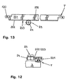
- Fign. 12 u. 13
- Darstellungen entsprechend den Fign. 8 und 9 zu einer fünften Bauart der y-Führung.
- Fig. 1
- a highly schematic partial representation of a machine tool with a movement unit with x-guidance and with y-guidance,
- Fig. 2
- 1 in the plan view of the movement unit,
- FIGS. 3 and 4
- partially cut representations of the x-guide according to FIGS. 1 and 2,
- Fig. 5
- a partially sectioned representation of the y-guide according to FIGS. 1 and 2,
- FIGS. 6 and 7
- Representations according to FIGS. 3 and 4 to a second type of x-guide,
- Fig. 8
- 5 shows a representation corresponding to FIG. 5 of a second type of y-guide,
- Fig. 9
- the y-guide of Fig. 8 in plan view,
- Fig. 10
- a representation according to FIGS. 5 and 8 to a third type of y-guide,
- Fig. 11
- a representation according to FIGS. 5, 8 and 10 to a fourth type of y-guide and
- FIGS. 12 u. 13
- Representations according to FIGS. 8 and 9 to a fifth type of y-guide.
Ausweislich Fig. 1 besitzt eine Werkzeugmaschine in Form einer
Stanzmaschine 1 ein C-förmiges Maschinengestell 2 mit einem
unteren Gestellschenkel 3 sowie einem oberen Gestellschenkel 4.
Beide Gestellschenkel 3, 4 sind in Fig. 1 abgebrochen dargestellt. As shown in FIG. 1 has a machine tool in the form of a
Punching machine 1 a C-shaped
An den freien Enden der Gestellschenkel 3, 4 ist die nicht im
Einzelnen gezeigte Bearbeitungs-, d.h. Stanzstation, der Stanzmaschine
1 vorgesehen. Diese Stanzstation ist herkömmlicher
Bauart und umfasst eine an dem unteren Gestellschenkel 3 angeordnete
Werkzeugaufnahme für das Stanz-Unterwerkzeug sowie eine
an dem oberen Gestellschenkel 4 vorgesehene Werkzeugaufnahme
für das Stanz-Oberwerkzeug.At the free ends of the
In dem Rachen der Stanzmaschine 1 ist zwischen dem unteren Gestellschenkel
3 und dem oberen Gestellschenkel 4 eine Bewegungseinheit
in Form einer Koordinatenführung 5 untergebracht.
Diese umfasst eine erste Bewegungsführung in Form einer x-Führung
6 sowie eine zweite Bewegungsführung in Form einer y-Führung
7.In the throat of the punching
Die x-Führung 6 weist als Tragstruktur eine x-Schiene 8 auf,
die sich in Richtung einer ersten Bewegungsachse, nämlich der
x-Achse 9, erstreckt. In Richtung der x-Achse 9 ist an der
x-Schiene 8 eine Mehrzahl von als Führungswagen 10 ausgebildeten
Führungseinheiten angetrieben bewegbar geführt. An einzelnen
Führungswagen 10 sind Pratzen 11, an anderen Werkzeugkassetten
12 angebracht. Die Pratzen 11 dienen in herkömmlicher
Weise zur Halterung eines Werkstücks in Form eines Blechs 13;
die Werkzeugkassetten 12 lagern jeweils ein als Stanzwerkzeug
14 ausgebildetes mehrteiliges Bearbeitungswerkzeug. An der nach
unten weisenden Seite sind die Führungswagen 10 mit an ihre
Wandung angeformten, im gezeigten Beispielsfall eingeschnittenen
Verzahnungsabschnitten 15 versehen.The
Die Verzahnungsabschnitte 15 an den in Richtung der x-Achse 9
aufeinander folgenden Führungswagen 10 schließen sich in der
genannten Richtung aneinander an und bilden auf diese Weise eine
versatzfreie Zahnstange 16. Mit der Zahnstange 16 kämmt ein
Antriebsritzel 17, das auf der Welle eines an der x-Schiene 8
gelagerten Antriebsmotors aufsitzt. Das Antriebsritzel 17 sowie
die Zahnstange 16 bzw. die Verzahnungsabschnitte 15 sind Teile
eines Antriebes in Form eines x-Antriebes 18, mittels dessen
die Führungswagen 10 in Richtung der x-Achse 9 an der x-Schiene
8 entlang bewegt werden können.The
In Richtung der x-Achse 9 ist die x-Schiene 8 ortsunveränderlich.
In Richtung einer zweiten Bewegungsachse, nämlich der y-Achse
19, kann die x-Schiene 8 mittels der y-Führung 7 verfahren
werden. Als Tragstruktur der y-Führung 7 fungiert der untere
Gestellschenkel 3 mit an seiner Oberseite angebrachten Führungsschienen
20. An dem unteren Gestellschenkel 3 bzw. an dessen
Führungsschienen 20 entlang bewegbar sind Führungseinheiten
in Form von Führungswagen 21. Ein Teil der Führungswagen 21 lagert
die x-Schiene 8. Sämtliche Führungswagen 21 sind an einer
Außenwand mit Verzahnungsabschnitten 22 versehen, die ebenso
wie die Verzahnungsabschnitte 15 an dem Führungswagen 10 in die
betreffende Wagenaußenwand eingeschnitten sind. Die Verzahnungsabschnitte
22 bilden eine versatzfreie Zahnstange 23. Mit
dieser kämmt ein Antriebsritzel 24, das auf der Welle eines
stationären Antriebsmotors angebracht ist. Die genannten Komponenten
bilden einen Antrieb in Form eines y-Antriebes 25, mittels
dessen die x-Schiene 8 in Richtung der y-Achse 19 verfahren
werden kann.In the direction of the x-axis 9, the
Wie in den Fign. 1 und 3 bis 5 angedeutet, sind die Führungswagen
10 der x-Führung 6 über einen Zuganker 26, die Führungswagen
21 der y-Führung 7 über einen Zuganker 27 miteinander verbunden.
Der Zuganker 26 verläuft dabei in Richtung der x-Achse
9, der Zuganker 27 in Richtung der y-Achse 19. Die Zuganker 26,
27 sorgen dafür, dass die Verzahnungsabschnitte 15, 22 in der
jeweiligen Bewegungsrichtung zusammenhängende und insofern versatzfreie
Zahnstangen 16, 23 bilden. Bei Bedarf können zwischen
einzelne Führungswagen 10, 21 zur Schaffung einer gleichförmigen
Verzahnung Distanzstücke eingelegt werden. Einen Beitrag
zur gegenseitigen Justage der einzelnen Führungswagen 10 bzw.
der einzelnen Führungswagen 21 leistet außerdem deren jeweilige
Lagerung an der x-Schiene 8 bzw. an dem unteren Gestellschenkel
3. Diese Lagerung ist quer zu der Bewegungsrichtung der Führungswagen
10, 21, also quer zu der x-Achse 9 bzw. der y-Achse
19 im Wesentlichen spielfrei. Schon mit dem Aufschieben der
Führungswagen 10, 21 auf die jeweilige Tragstruktur ergibt sich
somit eine gegenseitige Justage der Führungswagen 10, 21 und
dadurch eine Versatzfreiheit der von den Verzahnungsabschnitten
15, 22 gebildeten Zahnstangen 16, 23 quer zu der x-Achse 9 bzw.
der y-Achse 19.As in Figs. 1 and 3 to 5 indicated, are the
Wie im Einzelnen den Fign. 3, 4 und 5 zu entnehmen ist, sind
die Verzahnungsabschnitte 15, 22 an derjenigen Außenseite der
Führungswagen 10, 21 vorgesehen, welche der Abstützung der Führungswagen
10, 21 an der zugeordneten x-Schiene 8 bzw. der zugeordneten
Führungsschiene 20 des unteren Gestellschenkels 3
gegenüberliegt. Die Antriebskraft zur Bewegung der Führungswagen
10, 21 wird dementsprechend der Lagerung der Führungswagen
10, 21 unmittelbar gegenüberliegend eingeleitet.As shown in detail in FIGS. 3, 4 and 5 can be seen are
the
Ausweislich der Fign. 6 und 7 kann zur Verbindung der Führungswagen
10 und damit zur Bildung einer zusammenhängenden und versatzfreien
Zahnstange 16 aus den Verzahnungsabschnitten 15 anstelle
des Zugankers 26 eine Verbindungsleiste 28 vorgesehen
sein. Die Verbindungsleiste 28 ist dabei mit den Führungswagen
10 außen aufliegend verschraubt. Entsprechend kann gemäß den
Fign. 9 und 10 eine Verbindungsleiste 29 den zuvor beschriebenen
Zuganker 27 zur Kopplung der Führungswagen 21 der y-Führung
7 ersetzen.Evidenced the Fign. 6 and 7 can be used to connect the
Gegenüber den Verhältnissen nach den Fign. 5 und 8 abgewandelte
Bauarten der y-Führung 7 sind aus den Fign. 10 bis 13 ersichtlich.
Das Antriebsritzel 24 ist dabei an dem nach unten weisenden
Ende einer Motorwelle angebracht. Gegenüber den Verhältnissen
nach den Fign. 5 und 8 ebenfalls abgewandelt ist die Querschnittsform
von Führungsschienen 120 des unteren Gestellschenkels
3, welche die Führungswagen 21 bzw. Führungswagen 221 der
y-Führung 7 an konkaven Seitenwänden lagern.Compared to the conditions according to Figs. 5 and 8 modified
Types of y-
Gemäß den Fign. 12 und 13 sind die Führungswagen 221 der y-Führung
7 gegenüber den vorstehend beschriebenen Führungswagen 21
konstruktiv abgewandelt. Im Einzelnen sind die Führungswagen
221 in Richtung der y-Achse 19 mit Passungen 232 überlappend
miteinander verschraubt. Dadurch ist dafür gesorgt, dass in die
Führungswagen 221 eingeschnittene Verzahnungsabschnitte 222 eine
versatzfreie, zusammenhängende Zahnstange 223 bilden. Ausweislich
Fig. 12 sind die Verzahnungsabschnitte 222 an seitlichen
Vorsprüngen der Führungswagen 221 vorgesehen. Die Führungswagen
der x-Führung 6 können konstruktiv entsprechend gestaltet
sein. Generell besteht die Möglichkeit, die verschiedenen
Bauarten der x-Führung 6 bzw. der y-Führung 7 beliebig miteinander
zu kombinieren.According to FIGS. 12 and 13 are the
Bei Betrieb der Stanzmaschine 1, der wie üblich numerisch gesteuert
ist, werden das Blech 13 sowie die Stanzwerkzeuge 14
mittels der Koordinatenführung 5 in der durch die x-Achse 9 sowie
die y-Achse 19 definierten Ebene gegenüber der nicht gezeigten
Bearbeitungsstation bewegt bzw. positioniert. Die an
der x-Schiene 8 gehaltenen Stanzwerkzeuge 14 lassen sich dabei
in die Werkzeugaufnahmen an der Stanzstation einsetzen bzw. aus
den Werkzeugaufnahmen entnehmen. Eine detaillierte Beschreibung
dieser an sich bekannten Abläufe findet sich in DE-A-38 18 001.
Das Blech 13 gleitet bei seiner Bewegung in Richtung der x-Achse
9 auf einem Werkstücktisch 30, der an Führungswagen 21, 221
der y-Führung 7 gelagert ist und in Richtung der y-Achse 19
verfahren wird. Streben 31 sorgen für eine Versteifung der Koordinatenführung
5.When operating the punching
Claims (11)
- Motion unit on machine tools, with at least one drive (18, 25) and at least one motion guide (6, 7) associated with the drive (18, 25), wherein the drive (18, 25) comprises at least one rack (16, 23, 223) and at least one drive pinion (17, 24) meshing with the latter, and the motion guide (6, 7) comprises at least one bearing structure (8, 3) and a plurality of guide units (10, 21, 221) which are guided at the bearing structure (8, 3) and can move together by means of the drive (18, 25), characterised in that the rack (16, 23, 223) comprises tooth portions (15, 22, 222), at least a part of which is formed at least at some of the guide units (10, 21, 221) in one piece with the latter, and that the guide units (10, 21, 221) concerned are held adjusted relative to one another in order to form the rack (16, 23, 223).
- Motion unit according to Claim 1, characterised in that the tooth portions (15, 22, 222) are completely formed on the guide units (10, 21, 221) concerned.
- Motion unit according to any one of the preceding Claims, characterised in that the guide units (10, 21) concerned are held adjusted relative to one another by means of at least one tie rod (26, 27) which passes through them in their direction of motion (9, 19).
- Motion unit according to any one of the preceding Claims, characterised in that the guide units (10, 21) concerned are held adjusted relative to one another by means of at least one connecting strip (28, 29) which is fixed to them so as to rest externally thereon.
- Motion unit according to any one of the preceding Claims, characterised in that the guide units (221) concerned are held in overlapping fashion adjusted relative to one another.
- Motion unit according to any one of the preceding Claims, characterized in that the guide units (10, 21, 221) concerned are held by the bearing structure (8, 3) adjusted relative to one another transversely to their direction of motion by means of being supported by the bearing structure (8, 3) in a way substantially free from play in said direction.
- Motion unit according to any one of the preceding Claims, characterised in that the guide units (10, 21, 221) provided with the tooth portions (15, 22, 222) of the rack (16, 23, 223) are supported at an inner side lying opposite the bearing structure (8, 3), at which bearing structure (8, 3) they are mounted, and that the tooth portions (15, 22, 222) are provided at, in particular completely formed on, the guide units (10, 21, 221) at the outer side thereof lying opposite the inner side of the support.
- Motion unit according to any one of the preceding Claims, characterised in that the guide units (10, 21, 221) with tooth portions (15, 22, 222) are identical with one another.
- Motion unit according to any one of the preceding Claims in the form of a feed device by means of which at least one workpiece (13) and/or at least one machining tool (14) can move in the direction of at least one motion axis (9, 19) relative to a machining station, wherein the feed device comprises at least one motion guide (6, 7) whose guide units (10, 21, 221) provided with the tooth portions (15, 22, 222) of the rack (16, 23, 223) are guided at the associated bearing structure (8, 3) in the direction of a motion axis (9, 19) and are connected for motion to the workpiece(s) (13) and/or the machining tool(s) (14).
- Motion unit according to any one of the preceding Claims, characterised in that the feed device is formed as a coordinate guide (5) by means of which at least one workpiece (13) and/or at least one machining tool (14) can move in the direction of two motion axes (9, 19) relative to a machining station and which has two directional guides (6, 7) as motion guides, wherein the workpiece(s) (13) and/or the machining tool(s) (14) can move by means of the first directional guide (6) in the direction of the first motion axis (9) and by means of the second directional guide (7) together with the first directional guide (6) in the direction of the second motion axis (19), and wherein at least one of the directional guides (6, 7) comprises guide units (10, 21, 221) which have tooth portions (15, 22, 222) of the rack (16, 23, 223) and which are connected for motion to the workpiece(s) (13) and/or the machining tool(s) (14) or to the first directional guide (6) and the workpiece(s) (13) and/or the machining tool(s) (14).
- Machine tool with a motion unit according to any one of the preceding Claims.
Priority Applications (4)
| Application Number | Priority Date | Filing Date | Title |
|---|---|---|---|
| EP02005488A EP1344603B1 (en) | 2002-03-09 | 2002-03-09 | Motion unit of a machine tool and machine tool with such a motion unit |
| AT02005488T ATE299068T1 (en) | 2002-03-09 | 2002-03-09 | MOVEMENT UNIT ON MACHINE TOOLS AND MACHINE TOOL WITH SUCH A MOVEMENT UNIT |
| DE50203561T DE50203561D1 (en) | 2002-03-09 | 2002-03-09 | Moving unit on machine tools and machine tool with such a movement unit |
| US10/384,476 US20030172790A1 (en) | 2002-03-09 | 2003-03-07 | Motion mechanism for machine tools |
Applications Claiming Priority (1)
| Application Number | Priority Date | Filing Date | Title |
|---|---|---|---|
| EP02005488A EP1344603B1 (en) | 2002-03-09 | 2002-03-09 | Motion unit of a machine tool and machine tool with such a motion unit |
Publications (2)
| Publication Number | Publication Date |
|---|---|
| EP1344603A1 EP1344603A1 (en) | 2003-09-17 |
| EP1344603B1 true EP1344603B1 (en) | 2005-07-06 |
Family
ID=27763349
Family Applications (1)
| Application Number | Title | Priority Date | Filing Date |
|---|---|---|---|
| EP02005488A Expired - Lifetime EP1344603B1 (en) | 2002-03-09 | 2002-03-09 | Motion unit of a machine tool and machine tool with such a motion unit |
Country Status (4)
| Country | Link |
|---|---|
| US (1) | US20030172790A1 (en) |
| EP (1) | EP1344603B1 (en) |
| AT (1) | ATE299068T1 (en) |
| DE (1) | DE50203561D1 (en) |
Families Citing this family (3)
| Publication number | Priority date | Publication date | Assignee | Title |
|---|---|---|---|---|
| ITUB20160624A1 (en) * | 2016-02-10 | 2017-08-10 | Univ Degli Studi Genova | RECONFIGURABLE MACHINING CENTER |
| DE102018108015A1 (en) | 2017-04-07 | 2018-10-11 | Atlanta Antriebssysteme E. Seidenspinner Gmbh & Co. Kg | Rack with collar |
| IT201800020908A1 (en) * | 2018-12-21 | 2020-06-21 | Bystronic Laser Ag | Actuating device for upper sheet-pressing tools of an industrial machine for the bending of metal elements. |
Family Cites Families (9)
| Publication number | Priority date | Publication date | Assignee | Title |
|---|---|---|---|---|
| US3241243A (en) * | 1963-06-20 | 1966-03-22 | Coleman Engineering Company In | Hole center locating apparatus |
| GB1515947A (en) * | 1975-06-11 | 1978-06-28 | Beadle Ltd B | Buoyancy aids |
| US4054179A (en) * | 1976-05-26 | 1977-10-18 | Destree Allen L | Stone and concrete cutting machine |
| DE2805532A1 (en) * | 1978-02-10 | 1979-08-16 | Trumpf Maschinen Ag | MACHINE TOOL WITH AN ADJUSTABLE DEVICE FOR HOLDING AND MOVING A WORKPIECE AGAINST A TOOL |
| US4869141A (en) * | 1984-10-16 | 1989-09-26 | Trumpf Gmbh & Co. | Punch press with rotary ram and method of operating same |
| US5549024A (en) * | 1995-01-30 | 1996-08-27 | Ricci; Donato L. | Clamshell pipe lathe having improved bearing arrangement |
| US6494307B1 (en) * | 1997-09-08 | 2002-12-17 | Weld Tooling Corporation | Flexible track and carriage system |
| EP1205268B1 (en) * | 2000-11-08 | 2004-07-28 | Trumpf GmbH & Co | Machine tool with drive device |
| DE10103490A1 (en) * | 2001-01-26 | 2002-08-14 | Walter Gobbers | Toothed rack, to be operated by a rotating pinion, is composed of a number of interconnected links for flexibility on a curved path, and with drillings for locking bolts which act automatically on a straight path |
-
2002
- 2002-03-09 DE DE50203561T patent/DE50203561D1/en not_active Expired - Lifetime
- 2002-03-09 AT AT02005488T patent/ATE299068T1/en not_active IP Right Cessation
- 2002-03-09 EP EP02005488A patent/EP1344603B1/en not_active Expired - Lifetime
-
2003
- 2003-03-07 US US10/384,476 patent/US20030172790A1/en not_active Abandoned
Also Published As
| Publication number | Publication date |
|---|---|
| DE50203561D1 (en) | 2005-08-11 |
| EP1344603A1 (en) | 2003-09-17 |
| ATE299068T1 (en) | 2005-07-15 |
| US20030172790A1 (en) | 2003-09-18 |
Similar Documents
| Publication | Publication Date | Title |
|---|---|---|
| DE3240911A1 (en) | MACHINING CENTER | |
| EP3156175B1 (en) | Workpiece transfer device and machine tool with a workpiece transfer device | |
| EP3943239B1 (en) | Machine tool and method for operating same | |
| EP4117837B1 (en) | Bending machine | |
| DE102007004633B4 (en) | System for changing the tools in a woodworking machine | |
| EP0155332B1 (en) | Intermediate work piece support in a transfer press | |
| DE9414501U1 (en) | Processing machine with relatively displaceable turning devices | |
| DE3040711A1 (en) | Linearly movable tool carrier - has inverted U=section member with angled roller pairs inside flanges running on two round-section rails | |
| EP3416762B1 (en) | Press brake and method for changing bending tools of a press brake | |
| EP1287946B1 (en) | Machine tool with a functional unit driven by linear motors | |
| EP3075490B1 (en) | Machining unit | |
| EP1205268B1 (en) | Machine tool with drive device | |
| EP1344603B1 (en) | Motion unit of a machine tool and machine tool with such a motion unit | |
| EP1060810A2 (en) | Transfer feeder | |
| DE3101765A1 (en) | MACHINE TOOL WITH WORKPIECE INPUT ORGANS | |
| EP3416763B1 (en) | Press brake | |
| DE3825393C1 (en) | ||
| EP1137509B1 (en) | Machine tool with a horizontal work spindle | |
| EP3887091B1 (en) | Machine tool with a first and a second worktable | |
| DE10151631B4 (en) | Movement and / or positioning device | |
| EP1137508A2 (en) | Machine tool with a horizontal work spindle | |
| DE3440786C2 (en) | ||
| EP0701872A1 (en) | Installation for three-dimensional actuation of gripper bars | |
| EP3025803B1 (en) | Drive device for a machine tool and machine tool with such a drive device | |
| DE102019003613A1 (en) | Process for processing workpieces made of wood, plastic and the like |
Legal Events
| Date | Code | Title | Description |
|---|---|---|---|
| PUAI | Public reference made under article 153(3) epc to a published international application that has entered the european phase |
Free format text: ORIGINAL CODE: 0009012 |
|
| 17P | Request for examination filed |
Effective date: 20030208 |
|
| AK | Designated contracting states |
Kind code of ref document: A1 Designated state(s): AT BE CH CY DE DK ES FI FR GB GR IE IT LI LU MC NL PT SE TR |
|
| AX | Request for extension of the european patent |
Extension state: AL LT LV MK RO SI |
|
| AKX | Designation fees paid |
Designated state(s): AT BE CH CY DE DK ES FI FR GB GR IE IT LI LU MC NL PT SE TR |
|
| GRAP | Despatch of communication of intention to grant a patent |
Free format text: ORIGINAL CODE: EPIDOSNIGR1 |
|
| GRAS | Grant fee paid |
Free format text: ORIGINAL CODE: EPIDOSNIGR3 |
|
| GRAA | (expected) grant |
Free format text: ORIGINAL CODE: 0009210 |
|
| AK | Designated contracting states |
Kind code of ref document: B1 Designated state(s): AT BE CH CY DE DK ES FI FR GB GR IE IT LI LU MC NL PT SE TR |
|
| PG25 | Lapsed in a contracting state [announced via postgrant information from national office to epo] |
Ref country code: TR Free format text: LAPSE BECAUSE OF FAILURE TO SUBMIT A TRANSLATION OF THE DESCRIPTION OR TO PAY THE FEE WITHIN THE PRESCRIBED TIME-LIMIT Effective date: 20050706 Ref country code: NL Free format text: LAPSE BECAUSE OF FAILURE TO SUBMIT A TRANSLATION OF THE DESCRIPTION OR TO PAY THE FEE WITHIN THE PRESCRIBED TIME-LIMIT Effective date: 20050706 Ref country code: FI Free format text: LAPSE BECAUSE OF FAILURE TO SUBMIT A TRANSLATION OF THE DESCRIPTION OR TO PAY THE FEE WITHIN THE PRESCRIBED TIME-LIMIT Effective date: 20050706 Ref country code: IE Free format text: LAPSE BECAUSE OF FAILURE TO SUBMIT A TRANSLATION OF THE DESCRIPTION OR TO PAY THE FEE WITHIN THE PRESCRIBED TIME-LIMIT Effective date: 20050706 |
|
| REG | Reference to a national code |
Ref country code: GB Ref legal event code: FG4D Free format text: NOT ENGLISH |
|
| REG | Reference to a national code |
Ref country code: CH Ref legal event code: EP |
|
| REG | Reference to a national code |
Ref country code: IE Ref legal event code: FG4D Free format text: LANGUAGE OF EP DOCUMENT: GERMAN |
|
| REF | Corresponds to: |
Ref document number: 50203561 Country of ref document: DE Date of ref document: 20050811 Kind code of ref document: P |
|
| PG25 | Lapsed in a contracting state [announced via postgrant information from national office to epo] |
Ref country code: SE Free format text: LAPSE BECAUSE OF FAILURE TO SUBMIT A TRANSLATION OF THE DESCRIPTION OR TO PAY THE FEE WITHIN THE PRESCRIBED TIME-LIMIT Effective date: 20051006 Ref country code: GR Free format text: LAPSE BECAUSE OF FAILURE TO SUBMIT A TRANSLATION OF THE DESCRIPTION OR TO PAY THE FEE WITHIN THE PRESCRIBED TIME-LIMIT Effective date: 20051006 Ref country code: DK Free format text: LAPSE BECAUSE OF FAILURE TO SUBMIT A TRANSLATION OF THE DESCRIPTION OR TO PAY THE FEE WITHIN THE PRESCRIBED TIME-LIMIT Effective date: 20051006 |
|
| GBT | Gb: translation of ep patent filed (gb section 77(6)(a)/1977) |
Effective date: 20050917 |
|
| PG25 | Lapsed in a contracting state [announced via postgrant information from national office to epo] |
Ref country code: PT Free format text: LAPSE BECAUSE OF FAILURE TO SUBMIT A TRANSLATION OF THE DESCRIPTION OR TO PAY THE FEE WITHIN THE PRESCRIBED TIME-LIMIT Effective date: 20051212 |
|
| NLV1 | Nl: lapsed or annulled due to failure to fulfill the requirements of art. 29p and 29m of the patents act | ||
| REG | Reference to a national code |
Ref country code: IE Ref legal event code: FD4D |
|
| PG25 | Lapsed in a contracting state [announced via postgrant information from national office to epo] |
Ref country code: LU Free format text: LAPSE BECAUSE OF NON-PAYMENT OF DUE FEES Effective date: 20060331 Ref country code: BE Free format text: LAPSE BECAUSE OF NON-PAYMENT OF DUE FEES Effective date: 20060331 Ref country code: MC Free format text: LAPSE BECAUSE OF NON-PAYMENT OF DUE FEES Effective date: 20060331 |
|
| ET | Fr: translation filed | ||
| PLBE | No opposition filed within time limit |
Free format text: ORIGINAL CODE: 0009261 |
|
| STAA | Information on the status of an ep patent application or granted ep patent |
Free format text: STATUS: NO OPPOSITION FILED WITHIN TIME LIMIT |
|
| 26N | No opposition filed |
Effective date: 20060407 |
|
| BERE | Be: lapsed |
Owner name: TRUMPF WERKZEUGMASCHINEN G.M.B.H. + CO. KG Effective date: 20060331 |
|
| PGFP | Annual fee paid to national office [announced via postgrant information from national office to epo] |
Ref country code: CH Payment date: 20080304 Year of fee payment: 7 |
|
| PGFP | Annual fee paid to national office [announced via postgrant information from national office to epo] |
Ref country code: GB Payment date: 20080307 Year of fee payment: 7 |
|
| PGFP | Annual fee paid to national office [announced via postgrant information from national office to epo] |
Ref country code: AT Payment date: 20080229 Year of fee payment: 7 |
|
| PG25 | Lapsed in a contracting state [announced via postgrant information from national office to epo] |
Ref country code: CY Free format text: LAPSE BECAUSE OF FAILURE TO SUBMIT A TRANSLATION OF THE DESCRIPTION OR TO PAY THE FEE WITHIN THE PRESCRIBED TIME-LIMIT Effective date: 20050706 |
|
| PG25 | Lapsed in a contracting state [announced via postgrant information from national office to epo] |
Ref country code: ES Free format text: LAPSE BECAUSE OF NON-PAYMENT OF DUE FEES Effective date: 20060331 |
|
| PG25 | Lapsed in a contracting state [announced via postgrant information from national office to epo] |
Ref country code: AT Free format text: LAPSE BECAUSE OF NON-PAYMENT OF DUE FEES Effective date: 20090309 |
|
| REG | Reference to a national code |
Ref country code: CH Ref legal event code: PL |
|
| GBPC | Gb: european patent ceased through non-payment of renewal fee |
Effective date: 20090309 |
|
| PG25 | Lapsed in a contracting state [announced via postgrant information from national office to epo] |
Ref country code: CH Free format text: LAPSE BECAUSE OF NON-PAYMENT OF DUE FEES Effective date: 20090331 Ref country code: LI Free format text: LAPSE BECAUSE OF NON-PAYMENT OF DUE FEES Effective date: 20090331 |
|
| PG25 | Lapsed in a contracting state [announced via postgrant information from national office to epo] |
Ref country code: GB Free format text: LAPSE BECAUSE OF NON-PAYMENT OF DUE FEES Effective date: 20090309 |
|
| REG | Reference to a national code |
Ref country code: FR Ref legal event code: PLFP Year of fee payment: 15 |
|
| REG | Reference to a national code |
Ref country code: FR Ref legal event code: PLFP Year of fee payment: 16 |
|
| REG | Reference to a national code |
Ref country code: FR Ref legal event code: PLFP Year of fee payment: 17 |
|
| PGFP | Annual fee paid to national office [announced via postgrant information from national office to epo] |
Ref country code: FR Payment date: 20200319 Year of fee payment: 19 |
|
| PGFP | Annual fee paid to national office [announced via postgrant information from national office to epo] |
Ref country code: IT Payment date: 20200318 Year of fee payment: 19 |
|
| PGFP | Annual fee paid to national office [announced via postgrant information from national office to epo] |
Ref country code: DE Payment date: 20210319 Year of fee payment: 20 |
|
| PG25 | Lapsed in a contracting state [announced via postgrant information from national office to epo] |
Ref country code: FR Free format text: LAPSE BECAUSE OF NON-PAYMENT OF DUE FEES Effective date: 20210331 |
|
| REG | Reference to a national code |
Ref country code: DE Ref legal event code: R071 Ref document number: 50203561 Country of ref document: DE |
|
| PG25 | Lapsed in a contracting state [announced via postgrant information from national office to epo] |
Ref country code: IT Free format text: LAPSE BECAUSE OF NON-PAYMENT OF DUE FEES Effective date: 20210309 |