Technical Field
-
The present invention relates to a liquid nebulizing apparatus with
a liquid transport mechanism supplying liquid to a nebulizing part by a
constant amount stably.
Background Art
-
A conventional portable ultrasonic nebulizing apparatus generally
includes, for example, a reservoir for storing liquid (liquid medicine), a
oscillation source (an ultrasonic horn oscillator, for example) that is supplied
with the liquid in the reservoir at its tip, and a mesh member having
numerous fine pores and arranged so as to abut on the tip edge of the
oscillation source. The apparatus nebulizes the liquid in the reservoir by
the oscillation effect of the oscillation source and the mesh member.
-
Specifically, the liquid in the reservoir enters the gap between the
mesh member and the tip edge of the oscillation source, and by the
oscillation effect of the mesh member and the tip edge of the oscillation
source, the liquid is discharged as fine spray from the fine pores of the mesh
member.
-
In order to perform a stable nebulizing operation, it is required to
supply the nebulizing part stably with a constant amount of liquid from the
reservoir. Practically, however, the nebulization can not be stabilized due
to fluctuations in the liquid amount supplied of the nebulizing part. Such
fluctuation may be invited by the tilt of the apparatus under use, vibrations
from surrounding environment, the amount of the liquid remaining in the
reservoir or the like. Such an unstable nebulization fails to provide a spray
by a constant amount, and therefore it is not preferable to a liquid medicine
inhale medication, where a high concentration of liquid medicine should be
inhaled by a constant amount every time.
Disclosure of the Invention
-
The present invention is made in the light of the forgoing problem.
The primary object of the present invention is to provide a liquid nebulizing
apparatus in which a constant amount of liquid is transferred to a
nebulizing part so that a constant amount of liquid is nebulized every time,
and in which such a function is realized at low costs.
-
Another object of the present invention is to suppress excessive
power consumption as well as to reduce the driving time of an oscillation
means in an unloaded state, in order to extend the life of the oscillation
means.
-
Still another object of the present invention is to reduce the amount
of medicine failed to be inhaled by a user and thus wasted.
-
In order to achieve the objects above, a liquid nebulizing apparatus
according to a first aspect of the present invention includes a primary
reservoir for storing liquid to be nebulized; a nebulizing part for nebulizing
the liquid in the primary reservoir; a secondary reservoir provided between
the primary reservoir and the nebulizing part for measuring the liquid in
the primary reservoir by an amount to be transferred to the nebulizing part;
a primary liquid transfer part for transferring the liquid in the primary
reservoir to the secondary reservoir; a secondary liquid transfer part for
transferring the measured liquid in the secondary reservoir to the nebulizer
part; and an operation part for operating the secondary liquid transfer part.
-
In this nebulizing apparatus, the liquid in the primary reservoir is
not directly transferred to the nebulizing part, but it is transferred to the
secondary reservoir arranged between the primary reservoir and the
nebulizing part, where the liquid is measured by the amount per one
transfer. Then, thus measured liquid is transferred to the nebulizing part.
Accordingly, the liquid is supplied to the nebulizing part at a constant
amount irrespective of the tilt of the apparatus in use, vibrations from
surrounding environment, or the amount of the liquid remaining in the
reservoir, and hence, the nebulization is stabilized.
-
In a liquid nebulizing apparatus according to the present
embodiment, since the primary liquid transfer part and the secondary liquid
transfer part send liquid in accordance with the operation of the operation
part, respectively, a single operation of the operating part will transfer the
liquid in the primary reservoir to the secondary reservoir, and the liquid in
the secondary reservoir to the nebulizing part. Thus, the liquid is
transferred, measured and transferred again smoothly, providing improved
convenience.
-
Further, if the nebulizing part initiates the liquid nebulizing
operation simultaneously with the operation of the operation part, then not
only the operability of the apparatus is improved, but also the timing
between the liquid transfer to the nebulizing part and the nebulizing
operation can be adjusted suitably.
-
In this case, if the nebulizing part initiates the nebulizing operation
before being supplied with the liquid medicine, then the nebulizing part
starts nebulization immediately after being supplied with the liquid
medicine, thus the initiation of the nebulizing operation is rendered quick
and the nebulizing operation is stabilized.
-
Further, if the liquid is supplied to the secondary reservoir from the
primary reservoir when the liquid transfer operation to the nebulizing part
in accordance with the operation of the operation part is finished, then next
liquid transfer to the nebulizing part in accordance with the operation of the
operation part will be performed smoothly.
-
On the one hand, if the secondary reservoir is closed except for when
transferring liquid to the nebulizing part, then the liquid in the secondary
reservoir will not be exposed to the outer air, maintaining the liquid (liquid
medicine) to be inhaled by a person clean.
-
On the other hand, if the primary reservoir, the nebulizing part, the
secondary reservoir, the primary liquid transfer part and the secondary
liquid transfer part are integrally formed as a liquid supply unit with the
primary reservoir being removably mounted thereto, then the cleaning of
the primary reservoir for storing the liquid is facilitated.
-
A liquid nebulizing apparatus according to another aspect of the
present invention includes a reservoir chamber for storing liquid; a
measuring chamber to which a prescribed amount of the liquid is
transferred from the reservoir chamber via a liquid transfer port; a
nebulizing part for nebulizing the liquid supplied from the measuring
chamber via a liquid supply port; a piston for opening and closing the liquid
transfer port and pushing the liquid in the measuring chamber to supply the
liquid to the nebulizing part via the liquid supply port; and a piston drive
part for driving the piston at a constant rate.
-
By providing the piston drive part as above, the piston can be moved
at a constant rate and the liquid such as a liquid medicine can be pushed at
a substantially constant force. Therefore, the rate of the liquid to be
supplied to the nebulizing part can be made substantially constant, and the
liquid can be adhered to the nebulizing part as originally intended.
-
The liquid nebulizing apparatus preferably includes a valve
determining one end of the measuring chamber and supported by an elastic
member. The valve is moved by the piston pushing the liquid, thereby
opening the liquid supply port to supply the nebulizing part with liquid.
-
The nebulizing part includes a mesh member and an oscillator and
provided with the liquid from the measuring chamber. In this case, a
prescribed amount of the liquid can be supplied to a prescribed position on
the mesh member by including the piston drive part of the present
invention.
-
The piston driving part includes at least one element selected from
the group consisting of elasticity means applying elastic force to the piston, a
motor and a solenoid. In other words, the piston drive part of the present
invention is the one for driving the piston at a substantially constant force
such as an elastic force of a spring or the like, or a force obtained by utilizing
electromagnetic force such as a motor or a solenoid.
-
The liquid nebulizing apparatus above may include lock means for
fixing the piston at a position so as to be able to open the liquid transfer port
and transfer the liquid into the measuring chamber from the reservoir
chamber; and a release switch for releasing the fixed state brought by the
lock means and for actuating the piston driving means to drive the piston.
Thus, the piston can be driven only by turning the release switch on,
supplying the liquid to the nebulizing part in a constant amount by a simple
operation.
-
The liquid nebulizing apparatus above may include lock release
sensing means for sensing that the fixed state brought by the lock means is
released by the release switch; and nebulizing operation initiating means for
initiating a nebulizing operation of the liquid after the lock release sensing
means senses that the fixed state brought by the lock means is released by
the release switch. In this case, the nebulizing part can automatically be
actuated after the locked state of the piston is released. For example, the
liquid nebulizing operation can be initiated after the locked state of the
piston is released and a prescribed period is passed. Thus, the liquid
nebulization can be initiated simultaneously with or immediately after the
nebulizing part is supplied with the liquid. Note that, the nebulizing
operation initiating means are means for initiating an operation enabling
the nebulization of the liquid, including a case where the liquid actually
starts to be nebulized by the initiation of the nebulizing operation, and the
case where the liquid starts to be nebulized after a prescribed period is
passed.
-
Further, the piston driving part includes a first rod, a second rod for
pushing the piston, and a connecting member for connecting the first rod
and the second rod. The moving direction of the first rod and that of the
second rod are set to be different. Thus, the length of the liquid nebulizing
apparatus can be reduced in the moving direction of the piston, since the
piston driving part and piston needs not be aligned in a line. In special, by
arranging the first rod and the piston as well as the second rod in parallel
and driving the first rod and the second rod in the opposite direction, the
liquid nebulizing apparatus can be rendered compact.
-
Further, the liquid nebulizing apparatus above includes a housing
having the reservoir chamber inside; and a cylinder having the measuring
chamber inside and receiving the piston. In this case, preferably, the
cylinder and the piston driving part are removably mounted to the housing.
-
In the liquid nebulizing apparatus above, the piston driving part has
a spiral spring as elasticity means for applying elastic force to the piston.
Thus, a constant amount of liquid nebulization can easily be realized by
lowering the spring constant of the spiral spring. Additionally, the liquid
medicine is prevented from scattering in the nebulizing part, and the
apparatus can be rendered compact.
-
A liquid nebulizing apparatus according to another aspect of the
present invention includes a reservoir chamber for storing liquid; a
measuring chamber to which a prescribed amount of the liquid is
transferred from the reservoir chamber via a liquid transfer port; a
nebulizing part for nebulizing the liquid supplied from the measuring
chamber via a liquid supply port; a valve determining one end of the
measuring chamber and supported by an elastic member for opening and
closing the liquid supply port; a piston for opening and closing the liquid
transfer port and pushing the liquid in the measuring chamber, thereby
moving the valve to open the liquid supply port, whereby the nebulizing part
is supplied with the liquid via the liquid supply port; a piston driving part
for driving the piston; liquid supply sensing means for sensing initiation of
liquid supply to the nebulizing part in advance; and nebulizing operation
initiating means for initiating a nebulizing operation of the liquid in
response to the liquid supply sensing means sensing initiation of liquid
supply to the nebulizing part.
-
As above, by providing the liquid supply sensing means and the
nebulizing operation initiating means, the liquid nebulization operation can
automatically be initiated before of after the liquid supply to the nebulizing
part is initiated.
-
The liquid supply sensing means includes a position sensor for
sensing the position of at least one of the piston and the valve. In this case,
the nebulizing operation initiating means initiates the nebulizing operation
of the liquid in response to the position sensor sensing that at least one of
the piston and the valve reaches a prescribed position.
-
By providing the position sensor and the nebulization operation
initiating means, the liquid nebulization operation can automatically be
initiated when at least one of the piston and the valve reaches a prescribed
position. In this case, if the position sensor is set to sense the initiation of
liquid supply to the nebulizing part, then the liquid nebulizing operation
can be initiated immediately after or before the liquid is supplied to the
nebulizing part.
-
The piston driving part includes a motor and a solenoid. In this
case, the nebulizing operation initiating means initiates the a nebulizing
operation of the liquid after a driving signal of the motor or the solenoid is
input.
-
The nebulizing part includes a mesh member and an oscillator and
supplied with the liquid from the measuring chamber, while the nebulizing
operation initiating means includes oscillator driving means for driving the
oscillator.
-
In the liquid nebulizing apparatus above, the piston driving part has
a spiral spring as elasticity means for applying elastic force to the piston.
Thus, the liquid nebulization by a constant amount can easily be realized by
lowering the spring constant of the spiral spring. Additionally, the liquid
medicine is prevented from scattering in the nebulizing part, and the
apparatus can be rendered compact.
-
A liquid nebulizing apparatus according to another aspect of the
present invention includes a reservoir chamber for storing liquid; a
measuring chamber to which a prescribed amount of the liquid is
transferred from the reservoir chamber via a liquid transfer port; a
nebulizing part having a mesh member and an oscillator for nebulizing the
liquid supplied from the measuring chamber via a liquid supply port; a
piston for opening and closing the liquid transfer port and pushing the
liquid in the measuring chamber, thereby supplying the nebulizing part
with the liquid via the liquid supply port; a piston driving part for driving
the piston; impedance sensing means for sensing an impedance of the
oscillator; oscillation stopping means for stopping oscillation of the oscillator
in response to the impedance sensing means sensing that impedance is at
most a prescribed value.
-
The impedance of the oscillator is different when the liquid is
present on the mesh member and when not present on the mesh member.
Therefore, by sensing the impedance of the oscillator by the impedance
sensing means, the presence/absence of the liquid on the mesh member can
be sensed. Here, by providing the oscillator stopping means above, the
oscillation of the oscillator can be stopped in response to the impedance
sensing means sensing that impedance is at most a prescribed value. In
other words, the oscillation of the oscillator can be stopped when the absence
of the liquid to be nebulized on the mesh member is sensed.
-
In liquid nebulizing apparatus above, the piston driving part has a
spiral spring as elasticity means for applying elastic force to the piston.
Thus, the liquid nebulizing by a constant amount can easily be realized by
lowering the spring constant of the spiral spring. Additionally, the liquid
medicine is prevented from scattering in the nebulizing part, and the
apparatus can be rendered compact.
-
A liquid nebulizing apparatus according to another aspect of the
present invention includes a reservoir chamber for storing liquid; a
measuring chamber to which a prescribed amount of the liquid is
transferred from the reservoir chamber via a liquid transfer port; a
nebulizing part for nebulizing the liquid supplied from the measuring
chamber via a liquid supply port; a piston for opening and closing the liquid
transfer port and pushing the liquid in the measuring chamber, thereby
supplying the nebulizing part with the liquid via the liquid supply port; a
piston driving part for driving the piston; an inhalation port for a user to
inhale the liquid nebulized by the nebulizing part; and inhalation sensing
means for sensing the user inhaling from the inhalation port.
-
By providing the inhalation sensing means as above, it will be
possible to sense the user inhaling from the inhalation port. Thus, the
nebulization of the liquid or the liquid supply to the nebulizing part in
response to the user inhaling from the inhalation port may be possible.
Additionally, the shift in the timing of spraying the nebulized liquid and the
user's inhale can be reduced.
-
The liquid nebulizing apparatus above may include nebulizing
operation initiating means for initiating a nebulizing operation of the liquid
in the nebulizing part in response to the inhalation sensing means sensing
an inhalation of the user. The liquid nebulizing apparatus above may
include liquid supply means for supplying the liquid to the nebulizing part
in response to the inhalation sensing means sensing the inhalation of the
user.
-
In liquid nebulizing apparatus above, the piston driving part has a
spiral spring as elasticity means for applying elastic force to the piston.
Thus, the liquid nebulizing by a constant amount can easily be realized by
lowering the spring constant of the spiral spring. Additionally, the liquid
medicine is prevented from scattering in the nebulizing part, and the
apparatus can be rendered compact.
Brief Description of the Drawings
-
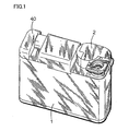
- Fig. 1 is an outer perspective view of a liquid nebulizing apparatus
according to an embodiment;
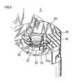
- Fig. 2 is a partially broken perspective view of a liquid supply unit in
liquid nebulizing apparatus according to the embodiment;
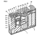
- Fig. 3 is a vertical cross sectional view of a liquid nebulizing
apparatus according to the embodiment;
- Fig. 4 is a schematic view showing a state where a secondary
reservoir is filled with a liquid medicine in a liquid transfer mechanism in a
liquid nebulizing apparatus according to the embodiment;
- Fig. 5 is a schematic view showing a state where the liquid medicine
in the secondary reservoir is pushed by a piston in the liquid transfer
mechanism in the liquid nebulizing apparatus according to the embodiment;
- Fig. 6 is a schematic view showing a state where the liquid medicine
in the secondary reservoir is transferred to a nebulizing part in the liquid
transfer mechanism in the liquid nebulizing apparatus according to the
embodiment;
- Fig. 7 is a schematic view showing a state where the liquid medicine
in the secondary reservoir is completely transferred to the nebulizing part in
the liquid transfer mechanism in the liquid nebulizing apparatus according
to the embodiment;
- Fig. 8 is a schematic view showing a state after the liquid medicine
in the secondary reservoir is transferred in the liquid transfer mechanism in
the liquid nebulizing apparatus according to the embodiment;
- Fig. 9 is a schematic view showing a state where a piston is drawn
back after the liquid medicine in the secondary reservoir is transferred in
the liquid transfer mechanism in the liquid nebulizing apparatus according
to the embodiment:
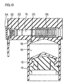
- Fig. 10 is a vertical cross sectional view showing a state
corresponding to Fig. 4 in the liquid transfer mechanism in the liquid
nebulizing apparatus according to the embodiment;
- Fig. 11 is a vertical cross sectional view showing a state
corresponding to Fig. 5 in the liquid transfer mechanism in the liquid
nebulizing apparatus according to the embodiment;
- Fig. 12 is a vertical cross sectional view showing a state
corresponding to Fig. 6 in the liquid transfer mechanism in the liquid
nebulizing apparatus according to the embodiment;
- Fig. 13 is a vertical cross sectional view showing a state
corresponding to Fig. 7 in the liquid transfer mechanism in the liquid
nebulizing apparatus according to the embodiment;
- Fig. 14 is a vertical cross sectional view showing a state
corresponding to Fig. 9 in the liquid transfer mechanism in the liquid
nebulizing apparatus according to the embodiment;
- Fig. 15 is a vertical cross sectional view showing a state in the main
part of the liquid nebulizing apparatus according to the embodiment where
a power supply switch is turned OFF;
- Fig. 16 is a vertical cross sectional view showing a state in the main
part of the liquid nebulizing apparatus according to the embodiment where
the power on switch is turned ON;
- Fig. 17 is a partially broken perspective view showing a state where
the nebulizing part is supplied with the liquid medicine from the secondary
reservoir in the liquid supply unit of the liquid nebulizing apparatus
according to the embodiment;
- Fig. 18 is a cross sectional view of the liquid nebulizing apparatus
according to a second embodiment of the present invention;
- Fig. 19 is an exploded perspective view of the liquid nebulizing
apparatus shown in Fig. 18;
- Fig. 20 is a partially broken perspective view showing an initial state
of the liquid nebulizing apparatus shown in Fig. 18;
- Fig. 21 is a partially broken perspective view showing an initial state
of the liquid nebulizing apparatus shown in Fig. 18;
- Fig. 22 is a partially broken perspective view showing a liquid
medicine discharge state of the liquid nebulizing apparatus shown in Fig.
18;
- Fig. 23 is a partially broken perspective view showing a liquid
medicine discharge complete state of the liquid nebulizing apparatus shown
in Fig. 18;
- Fig. 24 is a perspective view of a liquid nebulizing apparatus
according to a third embodiment of the present invention;
- Fig. 25 is an exploded perspective view of the liquid nebulizing
apparatus shown in Fig. 24;
- Fig. 26 is a partially broken perspective view showing an initial state
of the liquid nebulizing apparatus shown in Fig. 24;
- Fig. 27 is a partially broken perspective view showing a liquid intake
state of the liquid nebulizing apparatus shown in Fig. 24;
- Fig. 28 is a partially broken perspective view showing a liquid
medicine discharge state of the liquid nebulizing apparatus shown in Fig.
24;
- Fig. 29 is a partially broken perspective view showing a liquid
medicine discharge complete state of the liquid nebulizing apparatus shown
in Fig. 24;
- Fig. 30 is a block diagram showing a schematic configuration of a
liquid nebulizing apparatus according to a fourth embodiment of the present
invention;
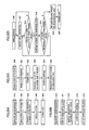
- Figs. 31A-31D are flow charts for describing an example of an
operation where an inhalation sensing is not performed by the liquid
nebulizing apparatus according to the fourth embodiment of the present
invention;
- Fig. 32A is a diagram showing changes in the voltage value of a horn
oscillator in a nebulizing operation;
- Fig. 32B is a diagram showing changes in impedance of the horn
oscillator;
- Figs. 33A-33D are flow charts showing an example of operation
where inhalation sensing is performed by the liquid nebulizing apparatus
according to the fourth embodiment of the present invention;
- Fig. 34A is a diagram showing changes in the voltage value of the
horn oscillator in a nebulizing operation;
- Fig. 34B is a diagram showing changes in impedance of the horn
oscillator;
- Figs. 35A-35D are flow charts showing another example of operation
where inhalation sensing is performed by the liquid nebulizing apparatus
according to the fourth embodiment of the present invention;
- Fig. 36 is a schematic view showing another example of a piston
driving part of the present invention;
- Fig. 37 is a schematic view showing still another example of the
piston driving part according to the present invention;
- Fig. 38 is a schematic view showing still another example of the
piston driving part according to the present invention;
- Fig. 39 is a schematic view showing still another example of the
piston driving part according to the present invention;
- Fig. 40 is an exploded perspective view of a liquid nebulizing
apparatus according to a fifth embodiment of the present invention;
- Fig. 41 is a partially broken perspective view of the liquid nebulizing
apparatus shown in Fig. 40;
- Fig. 42 is a view for describing a configuration supporting a lever
spring;
- Fig. 43 is a perspective view showing an initial state of a liquid
nebulizing apparatus shown in Fig. 40;
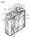
- Fig. 44 is a perspective view showing a wind up state of the liquid
nebulizing apparatus shown in Fig. 40; and
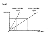
- Fig. 45 shows a relationship between the displacement amount of a
spring X and a force applied on a spring F.
-
Best Modes for Carrying Out Invention
-
In the following, the present invention will be described in further
detail by embodiments.
(First Embodiment) .
-
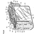
Fig. 1 is an outer perspective view of a liquid nebulizing apparatus
according to a first embodiment. The liquid nebulizing apparatus includes
a body 1 having a battery accommodation part 5 (see Fig. 3), an electric
circuit and the like inside, and a liquid supply unit 2 removably mounted to
the body 1.
-
Referring to Fig. 2, which is a partially broken perspective view of
liquid supply unit 2, and Fig. 3, which is a vertical cross sectional view
showing the interior of the apparatus, a primary reservoir 10 for storing
liquid (liquid medicine) to be nebulized is arranged inside the apparatus,
and to bottom part of primary reservoir 10, a movable member 12 that is
displaceable in upper and lower directions is attached watertight, movable
member 12 also being the bottom wall of primary reservoir 10. Movable
member 12 is set to be pressurized by a pushing member 14 arranged
beneath. Accordingly, the liquid medicine inside primary reservoir 10 is
pressurized. A primary liquid transfer part is formed by movable member
12, pushing member 14 and the like. Also, those parts forming primary
reservoir 10, movable member 12, and pushing member 14 are removable
from liquid supply unit 2, enabling easier cleaning.
-
A secondary reservoir 16 measuring the liquid amount to be
transferred to a nebulizing part is provided above primary reservoir 10, and
this secondary reservoir 16 communicates to primary reservoir 10 via liquid
transfer path 18. Secondary reservoir 16 is formed of a cylindrical space
extending in horizontal direction (a cylinder), and to one end of this
cylindrical space, a piston 20 is movably provided, and a valve 22 is
displaceably provided to the other end. A coil spring 56 is inserted into
piston 20, which is biased to the right direction in the figure by coil spring 56.
Though not shown in Fig. 3, valve 22 is biased to the right direction in the
figure by a coil spring 52 (see Figs. 4 and 10), and one end of coil spring 52
engages with a stopper 54 mounted to one end of a cylindrical space. A
secondary liquid transfer part is formed by piston 20, valve 22, liquid
transfer path 24, coil springs 52, 56 and the like.
-
Secondary reservoir 16 communicates to liquid transfer path 24,
which has an outlet 24a communicating to guide channel 26. Further, a
buffer part 28 is provided upper side of guide channel 26 for temporarily
storing part of the liquid medicine being transferred. Though guide
channel 26 and buffer part 28 are provided on a part different from
secondary reservoir 16 or liquid transfer path 24, they may be integrally
formed on a common part.
-
Secondary reservoir 16 communicates to liquid transfer path 24
when transferring liquid, otherwise it is closed. Specifically, even though
secondary reservoir 16 communicates to liquid transfer path 18 when the
liquid medicine is supplied from primary reservoir 10, the cleanliness of the
liquid medicine can be maintained since liquid transfer path 18 is filled with
the liquid medicine and the liquid medicine and secondary reservoir 16 will
not be exposed to the air.
-
A horn oscillator 30 is provided close to primary reservoir 10, with its
tip facing to guide channel 26. To the tip face of horn oscillator 30, a mesh
member 32 having numerous fine pores is abutted, which is pressed against
the tip face of horn oscillator 30 by an appropriate force of coil spring 34.
The nebulizing part is formed by horn oscillator 30 and mesh member 32.
-
By this configuration, the liquid medicine in primary reservoir 10 is
supplied to the gap between horn oscillator 30 and mesh member 32 via
liquid transfer path 18, secondary reservoir 16, liquid transfer path 24, and
guide channel 26.
-
A sliding liquid supply button 40 is provided on body 1 as an
operation part, which has a horizontal operating rod 42 for operating piston
20 provided at secondary reservoir 16, and an operating shaft 44 for
operating lever 46a of a power supply switch 46 provided below liquid
supply button 40. When supplying the liquid medicine to the nebulizing
part, liquid supply button 40 is slid to the left side in Fig. 3. Then,
operating rod 42 of liquid supply button 40 pushes piston 20, and
additionally, operating shaft 44 pushes lever 46a of power supply switch 46,
and thus power supply switch 46 turns ON. When liquid supply button 40
is released, piston 20 moves to the right side by the force of coil spring 56
and liquid supply button 40 returns to the state shown in Fig. 3, thereby
turning power supply switch 46 OFF.
-
The timing of turning power supply switch 46 ON is set earlier than
the liquid medicine in secondary reservoir 16 reaches the nebulizing part, so
that horn oscillator 30 is actuated before the liquid medicine is supplied to
the nebulizing part, to initiate the nebulization immediately when the
nebulizing part is supplied with the liquid. Thus, the nebulizing operation
starts quickly and the nebulizing operation is stabilized.
-
Since the liquid supply to the nebulizing part is performed by
operating the operation part, the nebulizing operation is initiated
simultaneously with the operation of the operation part. As used herein,
the nebulizing operation includes not only the process of nebulizing the
liquid medicine, but also the process of supplying the liquid medicine to the
nebulizing part, as will be described in detail later.
-
Regarding the nebulizing operation of the liquid medicine by the
liquid nebulizing apparatus, description will be given referring to schematic
views of Figs. 4-9. Those parts identical to the foregoing parts are provided
with the same reference characters. Referring to Fig. 4, cylinder 50
(corresponds to the cylindrical space forming secondary reservoir 16 above)
communicates to primary reservoir 10 (not shown in Figs. 4-9) via liquid
transfer path 18, as well as to guide channel 26 via liquid transfer path 24.
-
To one end inside cylinder 50, piston 20 also having a valve function
for opening/closing liquid transfer path 18 is movably arranged, and to the
other end, a valve 22 for opening/closing liquid transfer path 24 is
displaceably arranged. Piston 20 is biased downward in the figure by coil
spring 56 described above, and valve 22 is similarly biased downward by coil
spring 52. One end of coil spring 53 is attached to valve 22, and the other
end engages with a stopper 54 attached to the end of cylinder 50. Inside
cylinder 50, the space between piston 20 and the valve 22 forms secondary
reservoir 16, which is supplied with the liquid medicine from primary
reservoir 10. As shown in Fig. 5, the volume of secondary reservoir 16 can
be determined by [(12) 2π · L] where is an inner diameter and L is the
length of cylinder 50, and set to an appropriate amount required for one
transfer in advance.
-
According to thus structured liquid transfer mechanism, in the state
as shown in Fig. 4 where piston 20 opens liquid transfer path 18 while valve
22 closes liquid transfer path 24; since primary reservoir 10 is pressurized
with any given pressure, the liquid medicine in primary reservoir 10 flows
into secondary reservoir 16 in cylinder 50 via liquid transfer path 18, and
thus filling secondary reservoir 16 with a fixed amount of liquid medicine.
-
When liquid supply button 40 is slid in the state shown in Fig. 4,
piston 20 is pushed and moves to the direction shown by an arrow, the
upward direction in the figure), and the liquid medicine filled in the
secondary reservoir 16 is pressurized by piston 20, which in turn moves
valve 22 upward. When piston 20 further moves upward, liquid transfer
path 18 is closed by piston 20, and thus shutting the communication
between primary reservoir 10 and secondary reservoir 16 (see Fig. 5).
-
As piston 20 further moves upward, valve 22 moves upward as well,
opening liquid transfer path 24. The liquid medicine in secondary
reservoir 16 is discharged to guide channel 26 from outlet 24a via liquid
transfer path 24, and supplied to nebulizing part (see Fig. 6).
-
Valve 22 is fixed to any given position (herein to the position where
liquid transfer path 24 is completely opened) balanced by the pushing force
of piston 20 and discharging pressure of the liquid medicine from outlet 24a.
Accordingly, piston 20 moves until contacting to the fixed valve 22,
thereafter moves upward together with valve 22, and finally, moves until
valve 22 contacts to stopper 54 (see Fig. 7). In this state, the liquid
medicine in secondary reservoir 16 is completely discharged from outlet 24a.
-
At this time, as liquid supply button 40 is released, piston 20 is
pulled back by coil spring 56, and then liquid supply button 40 returns to the
original position, with valve 22 returning to the original position as well by
the bias force of coil spring 52. As shown in Fig. 8, at first piston 20 and
valve 22 moves together downward until valve 22 reaches the position for
closing liquid transfer path 24, and thereafter only piston 20 moves
downward as shown in Fig. 9.
-
In this state, as piston 20 further moves downward, secondary
reservoir 16 attains a negative pressure state. When piston 20 moves
enough to open liquid transfer path 18, the negative pressure of secondary
reservoir 16 and the pressure given to the liquid medicine in primary
reservoir 10 allows secondary reservoir 16 to be filled with the liquid in
primary reservoir 10 (see Fig. 4), whereby a standby state is attained until
next liquid supply operation. When liquid supply button 40 is slid again,
the operation above is repeated to supply the nebulizing part with the liquid
medicine by a fixed amount.
-
The liquid transfer mechanism as described above is actually
arranged in horizontal direction in the apparatus shown in Fig. 3. Next,
specific operation thereof will be described referring to Figs. 10-14. First,
in the Fig. 10 corresponding to the state shown in Fig. 4, the pressure
applied to primary reservoir 10 enables to fill secondary reservoir 16 with
the liquid medicine by a fixed amount via liquid transfer path 18. At this
time, lever 46a of power supply switch 46 is not operated by operating shaft
44 of liquid supply button 40, and power supply switch 46 is in OFF state
(see Fig. 15).
-
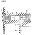
In Fig. 11 corresponding to the state shown in Fig. 5, piston 20 is
pushed by operating rod 42 when liquid supply button 40 is slid and thus
moves in the direction indicated by an arrow, and valve 22 also moves in the
direction indicated by an arrow to close liquid transfer path 18 by piston 20.
At this time, as shown in Fig. 16, since liquid supply button 40 moves to left,
the lever 46a of power supply switch 46 is pushed by operating shaft 44 to
turn power supply switch 46 on, and hence, horn oscillator 30 is actuated
before the liquid medicine is supplied to the nebulizing part.
-
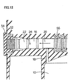
In Fig. 12 corresponding to the state shown in Fig. 6, liquid transfer
path 24 is opened by the movement of valve 22, allowing the liquid medicine
in secondary reservoir 16 to flow into liquid transfer path 24, and further to
be supplied to nebulizing part via guide channel 26.
-
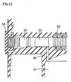
In Fig. 13 corresponding to the state shown in Fig. 7, piston 20 is
moved until contacting to valve 22, which allows the fixed amount of the
liquid medicine in secondary reservoir 16 to be completely transferred from
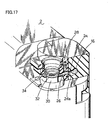
liquid transfer path 24 to nebulizing part. It should be noted, the liquid
medicine is not supplied to the nebulizing part at once, but as shown in Fig.
17, a part of the liquid medicine is temporarily stored in buffer part 28
provided to guide channel 26 so that an appropriate amount of the liquid
medicine is supplied to the nebulizing part gradually.
-
In Fig. 14 corresponding to the state shown in Fig. 9, piston 20
recovers by coil spring 56 as well as valve 22 recovers its original position by
coil spring 52, and liquid transfer path 24 is closed by valve 22. Secondary
reservoir 16 enters a negative state by the recovery of piston 20, and when
piston 20 opens liquid transfer path 18, it returns to the state shown in Fig.
10 to fill secondary reservoir 16 with the liquid medicine from primary
reservoir 10, preparing for the next liquid transfer operation.
-
As has been described, according to the present invention, since the
liquid in primary reservoir 10 is not transferred directly to the nebulizing
part, but it is temporarily transferred to secondary reservoir 16,provided
between primary reservoir 10 and the nebulizing part, where the liquid
medicine is measured by the amount per one transfer to the nebulizing part,
and thus measured nebulizing liquid is transferred to the nebulizing part, a
constant amount of liquid to is supplied to the nebulizing part irrespective of
the tilt of the apparatus in use, vibrations from surrounding environment,
the amount of the liquid remaining in the reservoir or the like, and hence,
the nebulizing operation is stabilized. Additionally, it can be realized by an
inexpensive structure.
(Second Embodiment)
-
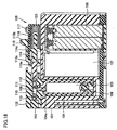
As shown in Figs. 18 and 19, the liquid nebulizing apparatus
includes a housing 101, a cylinder 102, a piston driving part 126, and a
nebulizing part 127.
-
As shown in Fig. 18, a battery 108 as a power supply part, and a
nebulizing part driving circuit board 107 for driving the nebulizing part are
provided inside housing 101. As shown in Fig. 19, a recess is provided to
the sidewall of housing 101, to which an ampoule 104 containing a liquid
such as a liquid medicine is attached.
-
As shown in Fig. 18, ampoule 104 has a reservoir chamber 105, a
piston 106, and a liquid supply route 104a. A liquid medicine (liquid) is
stored in reservoir chamber 105 and supplied to measuring chamber 109,
which will be described later, from reservoir chamber 105 via liquid transfer
route 104a and liquid transfer port 111.
-
Cylinder 102 is removably attached to housing 101 to accommodate
piston 112. Cylinder 102 has a valve cover 103, measuring chamber 109, a
discharge valve 113, a valve spring 118 and a supply port 110.
-
Piston 112 opens/closes liquid transfer port 111 to supply the liquid
medicine from reservoir chamber 105 into measuring chamber 109, and
further, supplies the liquid medicine to nebulizing part 127 via liquid supply
port 110 by pushing the liquid medicine in measuring chamber 109.
-
Measuring chamber 109 shown in Fig. 18 is for measuring the liquid
medicine by a fixed amount, one wall of measuring chamber 109 being
formed by an edge face of piston 112, while the other wall being formed by
an edge face of discharge valve 113.
-
Discharge valve 113 is elastically supported by cylinder 102 via an
elastic member such as valve spring 118, and movable to left or right
direction (in horizontal direction) in Fig. 18. By pushing the liquid
medicine in measuring chamber 109 by piston 112, discharge valve 113 is
pressurized, which in turn compresses valve spring 118 and moves
discharge valve 113 to the left direction in Fig. 18. Thus, liquid supply port
110 can be opened.
-
Liquid supply port 110 opens to measuring chamber 109 and
communicates to a liquid supply route (not shown) for transferring the
liquid medicine from measuring chamber 109 to nebulizing part 127. The
liquid medicine supplied to nebulizing part 127 is sprayed after nebulization
and thus inhaled by a patient.
-
Piston driving part 126 drives piston 112 at a constant rate, and
being removably mounted to housing 101. This piston driving part 126 has,
in the present embodiment, a rod 114, a lever 115, a piston spring 116, a
release button 117, a rod case 123, and a screw 124.
-
Rod 114 extends in the horizontal direction and connected to piston
112, and pushing the piston 112 to the left direction in Fig. 18. Rod 114 has
a flange part 114c, to which one end of piston spring 116 is attached or
abutted.
-
Piston spring 116 provides a constant elastic force to piston 112 via
rod 114, and thus moves piston 112 in horizontal direction at a constant rate.
This piston spring 116 and rod 114 are both accommodated in rod case 123,
the other end of piston spring 116 being supported on the wall of rod case
123. Rod case 123 is fixed to housing 101 by screw 124.
-
Lever 115 is mounted so as to cover one end of rod case 123 and it is
used for recovering piston 112 and rod 114 to the original position against
the elastic force of piston spring 116.
-
Lever 115 has a pair of engaging hooks 115a and a projection part
(operation part) 115b protruding upward. One end of piston 112 is
accommodated between engagement hooks 115a, such that engaging hooks
115a are engaged with a flange part 112a provided at one end of piston.
-
By pushing protrusion 115b to slide lever 115 to the right side in the
Fig. 18, rod 114 and piston 112 moves to the right side in Fig. 18.
-
Release button 117 is operable by pushing in vertical direction and
has a lock hook 125. Lock hook 125 engages with a flange part 114c of rod
114, to limit the movement of rod 114 toward the left direction. Accordingly,
when pushing protrusion part 115b by hand to move piston 112 and rod 114
to the right side, piston 112 and rod 114 can be locked at the position where
liquid transfer port 111 can be opened to transfer the liquid medicine from
reservoir chamber 105 to measuring chamber 109. At this time, piston
spring 116 is compressed and elastic force resulted therefrom is applied to
rod 114.
-
For releasing the locked state of piston 112 and rod 114, release
button 117 should be pressed downward. Lock hook 125 and flange part
114c of rod 114 are thus disengaged, with piston driving part 126 starting to
actuate simultaneously, and piston 112 and rod 114 being moved to left side
by the elastic force of piston spring 116 which has been compressed.
-
As above, by providing lock hook 125 of locking means and release
button 117 of a release switch, piston 112 can be driven only by pushing
release button 117, thus the fixed amount of liquid medicine can be supplied
to nebulizing part 127 by a simple operation.
-
The liquid nebulizing apparatus as described above preferably
includes a lock release sensing part for sensing that the locked state brought
by lock hook 125 is released by release button 117, and a nebulizing
operation initiation part for initiating the nebulizing operation of the liquid
medicine after sensing that the locked state brought by lock hook 125 is
released by release button 117.
-
In this case, nebulizing part 127 can be actuated automatically after
releasing the locked state of piston 112, whereby, for example, the
nebulizing operation of the liquid medicine can be initiated when a
prescribed period is passed after the locked state of piston 112 is released.
Thus, nebulizing part 127 can initiate nebulization of the liquid medicine
when supplied with the liquid medicine, or immediately after that.
-
As shown in Fig. 19, nebulizing part 127 includes horn oscillator
(ultrasonic oscillator) 119, mesh member 120, mesh member holder 121, and
mesh member cap 122.
-
Mesh member 120 has numerous fine pores, and placed on the tip
edge of horn oscillator 119. At this time, mesh member 120 is pressed
against the tip edge of horn oscillator 119 by mesh member holder 121
accommodating a coil spring. Mesh member cap 122 is mounted on mesh
member holder 121.
-
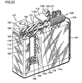
Next, referring to Figs. 20-23, the operation of liquid nebulizing
apparatus according to the second embodiment of the present invention will
be described.
-
At an initial state shown in Fig. 20, projection part 115b of lever 115
is manually pressed to the right side. Thus, as shown in Fig. 21, lever 115
moves to the right side, with piston 112 and rod 114 together moving to the
right side. At this time, piston spring 116 is pressed by flange part 114c of
rod 114, and thus compressed.
-
Additionally, by the movement of the piston 112 toward the right
side, liquid transfer route 104a and liquid transfer port 111 communicate to
measuring chamber 109, filling measuring chamber 109 under negative
pressure with the liquid medicine from reservoir chamber 105.
-
When lever 115 is moved by a predetermined amount, the extension
part extending from one end of flange part 114c of rod 114 to the
longitudinal direction of rod 114 engages with lock hook 125 of release
button 117, thus locking lever 115, piston 112 and rod 114 at a prescribed
position.
-
Next, release button 117 is pressed downward. Thus, the extension
part of flange part 114c and lock hook 125 can be disengaged, and piston 112
and rod 114 can be pressed by the elastic force of piston spring 116 that has
been compressed.
-
As above, by pushing piston 112 and rod 114 by substantially
constant force of such an elastic force, as shown in Fig, 22, piston 112 and
rod 114 can be moved to the left side at an approximately constant rate. In
other words, the liquid medicine in measuring chamber 109 can be pushed
by piston 112 with substantially uniform force. Thus, discharge valve 113
is pushed by the liquid medicine, moving to the left side to open liquid
supply port 110.
-
Then, the liquid medicine can be supplied to nebulizing part 127
through liquid supply port 110. Since piston 112 is driven at a
substantially constant rate, the rate (momentum) of the liquid medicine
supplied to nebulizing part 127 can be kept approximately constant. In
other words, the liquid medicine will not be supplied to nebulizing part 127
at an excessive rate and the momentum of the liquid medicine will not be too
weak.
-
As a result, the liquid medicine can be adhered to the position as
originally intended in nebulizing part 127 with a desired current, thus the
liquid medicine is reliably and efficiently nebulized by nebulizing part 127,
reducing the liquid amount remaining in the nebulizing part 127 being
failed to be nebulized.
-
Thereafter, piston 112 moves to the position where it almost abuts
on discharge valve 113 as shown in Fig. 23, making the fixed amount of
liquid medicine fully discharged from the measuring chamber 109.
Accordingly, the discharge of the liquid medicine from measuring chamber
109 is completed.
-
According to the present embodiment, as compared to the first
embodiment, the piston can be driven at a constant rate. This will be
described in the following.
-
In the first embodiment described above, since liquid supply button
40 is operated manually, variations may result in the force applied to liquid
supply button 40. The variations in the force applied to liquid supply
button 40 may result in variations in moving rate of piston 20, which in turn
affect the rate of the liquid medicine supplied into the nebulizing part.
-
If the rate of the liquid medicine discharged into the nebulizing part
is too fast, then the liquid medicine will be scattered in the nebulizing part,
while if the rate of the liquid medicine discharged into the nebulizing part is
too slow, then the liquid medicine will not reach a predetermined position in
the nebulizing part. As a result, the liquid medicine will not be adhered to
the nebulizing part against the original intention, increasing the liquid
amount remaining in nebulizing part not being nebulized.
-
A liquid spraying apparatus is disclosed in WO00/66277, which has
pushing mechanism to stroke a piston by a prescribed amount
accommodated in a liquid bottle by operating a manual operating member,
to supply a fixed amount of liquid into a spray chamber by a simple
operation. In this case also, since the piston is driven by a manual
operation, the liquid medicine will not be adhered to the nebulizing part as
the original intention similarly to the aforementioned example, and thus
increasing the liquid amount remaining and nebulizing part not being
nebulized.
-
In contrast thereto, according to the present embodiment, since
piston 112 and rod 114 are pushed by the elastic force of piston spring 116,
piston 112 can be driven at a constant rate. Thus, the problem above can
be avoided.
(Third Embodiment)
-
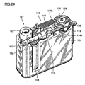
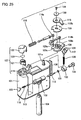
Next, referring to Figs. 24-29, a third embodiment of the present
invention will be described.
-
As shown in Figs. 24 and 25, the third embodiment is different from
the first embodiment in that the configuration of piston driving part 126 for
driving piston 112 is modified. The rest of the configuration is basically the
same as that of the second embodiment.
-
Piston driving part 126 according to the third embodiment includes,
as shown in Figs. 24 and 25, rods 114a, 114b, lever 115, piston string 116,
release button 117, upper lever plate 128, lower lever plate 129, lever cover
130, and screw 134.
-
Rod 114a has a small diameter part and a large diameter part at one
end, and a ring-form part at the other end. The small diameter part is
received by U-shaped recess of a support wall provided on top face of
housing 101. Accordingly, the large diameter part and the supporting wall
can be engaged, mounting rod 114a to housing 101.
-
A flange part is provided at the middle portion of rod 114a, and
piston spring 116 is provided between the flange part and the supporting
wall. This piston spring 116 can push the flange part, driving rod 114a to
the right side in Fig. 24.
-
Rod 114b has a pin part projecting above at one end, and a ring form
part at the other end. The pin part is inserted and fixed to the ring-form
part of piston coupling rod 113. A tube part is provided at one end of piston
coupling rod 113, which is inserted into piston cover 132, and one end of
piston 112 is inserted in the tube part via piston stopper 131.
-
Rods 114a, 114b are connected by upper and lower lever plates 128,
129 that are the connecting members. As shown in Fig. 25, upper and
lower lever plates 128, 129 have a perforation hole and a boss part 129c,
respectively, for receiving cylindrical part 101a provided on the top face of
housing 101, and attached to housing 101 rotatably.
-
Lower lever plate 129 has a pair of pins 129a, 129b at opposing sides
of boss part 129c, and connected to rod 114a by pin 129a and to rod 114b by
pin 129b. More specifically, by inserting pins 129a, 129b into the ring-form
parts of rod 114a, 114b, respectively, rod 114a, 114b can be connected to
lower lever plate 129.
-
As shown in Figs. 24 and 25, rod 114a and 114b are arranged
substantially parallel to each other, with their moving direction being
opposite to each other. By arranging the moving directions of rod 114a,
114b opposite to each other, the needs to place piston driving part 126 and
piston 112 in a line is eliminated, thus reducing the length of the liquid
nebulizing apparatus in the moving direction of piston 112. By arranging
rods 114a, 114b substantially parallel to each other, the length of the liquid
nebulizing apparatus can be reduced in the width direction also, thus
making the liquid nebulizing apparatus compact.
-
As shown in Fig. 25, lever 115 includes a perforation hole for
accommodating cylindrical part 101a at its middle portion, and a long hole
for accommodating pin 129b. This lever 115 is in flat shape, and has a
protrusion (operation part) 115b protruding to the radial direction. By
pushing this protrusion part manually, lever 115 can be turned.
-
Lever cover 130 is placed on lever 115, and screw 134 is screwed into
the cylindrical part 101a from above this lever cover 130. Thus, lever cover
130, lever 115, upper and lower lever plates 128, 129 can be mounted to
housing 101.
-
Release button 117 is elastically supported by release spring 135
accommodated in the spring case 136 provided at a sidewall of housing 101.
This release button 117 has lock hook 125, which is inserted into a
perforation hole provided to lower lever plate 129. Thus, lower lever plate
129 is locked.
-
In order to release this locked state, the operation part of release
button 117 is manually pushed down. Thus, lock hook 125 moves
downward and released from the perforation hole of lower lever plate 129,
thereby disengaging the locked states of lower lever plate 129.
-
Next, referring to Figs. 26-29, the operation of the liquid nebulizing
apparatus according to the present embodiment will be described.
-
From the initial state shown in Fig. 26, protrusion part 115b of lever
115 is manually turned to left (counterclockwise), thus turning lever 115 by
a prescribed angle. Accordingly, upper and lower lever plates 128, 129 as
shown in Fig. 27 rotate and rod 114b moves to the right side, and piston 112
moves to the right side as well. At this time, rod 114a moves to the left side,
and piston spring 116 is pressed by the flange part of rod 114a and thus
compressed.
-
As piston 112 moves to the right side at least by a prescribed amount,
liquid transfer port 111 opens to transfer the liquid medicine from reservoir
chamber 105 to measuring chamber 109 as in the second embodiment. At
this time, the liquid supply hole is closed by discharge valve 113.
-
As lever 115 is turned by a prescribed amount, lock hook 125 is
inserted into the perforation hole provided at lower lever plate 129 as shown
in Fig. 27, thereby locking piston 112 and other parts at a prescribed
position.
-
Next, by pushing down release button 117, lock hook 125 is released
from the perforation hole provided at lower lever plate 129 as shown in Fig.
28, thereby disengaging lower lever plate 129 and lock hook 125. Thus, rod
114a, rod 114b, and upper and lower lever plates 128, 129 can be driven by
the elastic force of piston spring 116 that has been compressed, thereby
moving piston 112 to the left side.
-
As above, by pushing piston 112 with the elastic force of spring,
similarly to the second embodiment, the liquid medicine in the measuring
chamber 109 can be pushed by piston 112 with substantially uniform force.
-
Thus, discharge valve 113 is pressurized by the liquid medicine and
moves to the left side, thereby opening the supply port 110, through which
the liquid medicine is provided to the nebulizing part 127. In the present
embodiment also, since piston 112 is driven at an approximately constant
rate, the same effect as in the second embodiment can be attained.
-
Thereafter, piston 112 moves to the position where it almost abuts
on discharge valve 113 as shown in the Fig. 29, supplying nebulizing part
127 with all of the fixed amount of the liquid medicine from measuring
chamber 109. Thus, the discharge of the liquid medicine from measuring
chamber 109 is completed.
-
As in the second embodiment, since the present embodiment enables
to push piston 112 by the elastic force of piston spring 116, piston 112 can be
driven at a constant rate.
(Fourth Embodiment)
-
In the following, referring to Figs. 30-39, a fourth embodiment of the
present invention and its modification will be described.
-
Though in the second and third embodiments above, the elastic
member such as a spring is applied as driving means of piston 112, piston
112 can be driven with a constant force (rate) using an electromagnetic force
such as motor or a solenoid. In the present embodiment, an example using
not only a spring but also motor or solenoid is used to drive piston 112 will
be described.
-
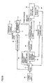
As shown in Fig. 30, a liquid nebulizing apparatus according to the
present embodiment includes a power supply part 150, a control part 151, a
liquid medicine presence/absence sensing part 152, a constant current
boosting circuit 153, an oscillator circuit 154, nebulizing part 127, a current
sensing part 155, mesh member cap 122, an inhalation sensor 156, piston
driving part 126, reservoir chamber 105, liquid transfer port 111, piston 112,
measuring chamber 109, discharge valve 113 andiiquid supply port 110.
-
Power supply part 150 is structured by a dry cell and the like.
Control part 151 controls an operation of each part. Constant current
boosting circuit 153 boosts the output of power supply part 150, thus
constant-current drives oscillator circuit 154 and nebulizing part 127.
-
As in the second embodiment and others, nebulizing part 127
includes an ultrasonic oscillator (horn oscillator) and a mesh member.
Current sensing part 155 senses the current passing through ultrasonic
oscillator to attain constant current in constant current boosting circuit 153.
-
Liquid medicine presence/absence sensing part 152 senses the
presence/absence of the liquid medicine in nebulizing part 127 and inputs
the sensing result to control part 151, which controls constant current
boosting circuit 153 to turn ON/OFF.
-
The presence/absence of the liquid medicine on the ultrasonic
oscillator depends on the impedance of ultrasonic oscillator. Specifically,
when the liquid medicine is present on the ultrasonic oscillator, the
impedance is high, and when the liquid medicine is not present on the
ultrasonic oscillator, the impedance is low.
-
When the impedance of the ultrasonic oscillator increases, the input
impedance of oscillator circuit 154 increases as well, thereby increasing the
output voltage of constant current boosting circuit 153. This voltage is
input to control part to sense the presence/absence of the liquid medicine on
the ultrasonic oscillator.
-
Inhale sensor 156 senses the inhalation of a patient (user), and in
response to the sensing result, the control part 151 controls constant current
boosting circuit 53 to turn ON/OFF. This inhalation sensor 156 is provided
at or around mesh cap (a mouthpiece: inhalation port) 122, for sensing that
the patient is inhaling the liquid medicine nebulized by the nebulizing part
127 from inhalation port. In order to sense the inhalation, a difference in
pressure or a change in airflow resulted by the inhalation of the patient
should be sensed.
-
By providing inhalation sensor 156 as above, the inhalation of the
patient from the inhalation port can be sensed, and in response thereto, the
nebulization of the liquid medicine or the supply of the liquid medicine to
nebulizing part 127 can be performed, reducing the shift in the timing of
spraying nebulized liquid medicine and the inhalation of the patient.
-
As for piston driving part 126, the configuration as in the second and
third embodiments can be employed, and additionally, a configuration
shown in Figs. 36-39 can also be employed.
-
For example, as shown in Fig. 36, piston 112 can be driven using
solenoid 138. In this case, by conducting solenoid 138, pin 137 moves to the
left side, moving piston 112 to the left side through rod 114. Thus, piston
112 can be driven at a constant rate.
-
Further, as shown in Fig. 37, piston 112 can be driven using motor
139. In this case, rod 114 is geared, with motor 139 and rod 114 connected
with a pinion gear 140. Thus, the driving motor 139 rotates pinion gear
140, thereby moving piston 112 to the left side at a constant rate through rod
114.
-
Still further, as shown in Fig. 38, it is also possible to fix rod 114 to
gear 142, and to fix gear 141 to the side of motor 139, engaging gear 141 and
gear 142. Thus, the power from motor 139 can be transmitted to rod 114
via gears 141 and 142, thereby moving piston 112 to the left side at a
constant rate.
-
Still further, as shown in Fig. 39, piston 112 can be driven using
rotary solenoid 145. In this case, the rotation of rotary solenoid 145 rotates
arm 143 fixed to shaft 144, whereby rod 114 fixed on arm 143 is pushed to
drive piston 112. Thus, piston 112 can be moved to the left side at a
constant rate.
-
Since mesh member cap 122, discharge valve 113, reservoir chamber
105, measuring chamber 109, piston 112, liquid supply port 110, and liquid
transfer port 111 may be the same as in the second and third embodiments,
their specific description will not be repeated. Additionally, when piston
drive part 126 includes a spring, it is not necessary to control piston drive
part 126 by control part 151.
-
Next, the operation of the liquid nebulizing apparatus according to
the present embodiment will be described.
-
First, referring to Figs. 31A-31D, Figs. 32A and 32B, an operation
will be described in which an inhalation sensing is not performed.
-
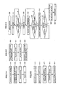
As shown in Fig. 31A, at step S10, the liquid medicine is measured
by a fixed amount. The manner of measuring the liquid medicine is the
same as in the second and third embodiments. Specifically, as shown in
Fig. 31B, the liquid supply lever is wound up (step Si 1), and piston 112 is
driven to open liquid transfer port 111, thereby supplying measuring
chamber 109 with the liquid medicine from reservoir chamber 105 (step S12).
At this time, the spring is compressed (step S13), and the extension of the
spring is latched in the same manner as in the second and third
embodiments (step S 14).
-
Next, in step S20 in Fig. 31A, the liquid medicine is transferred to
nebulizing part 127. The transfer of the liquid medicine is performed by, as
shown in Fig. 31C, releasing the latch of the spring by operating the release
button as described in the second and third embodiments (step S21), to
extend the spring (step S22). Thus, piston 112 is pushed by spring via rod
114, then the liquid medicine in measuring chamber 109 is pushed by piston
112 and discharge valve 113 moves to open liquid supply port 110, thereby
transferring the liquid medicine to nebulizing part 127 (step S23).
-
Next, at step S30 in Fig. 31A, the liquid medicine is nebulized in
nebulizing part 127 and sprayed. The spraying of the liquid medicine will
be performed in the following manner. First, as shown in Fig. 31D, rod 114
moves by the elastic force of the spring (step S31), the position of rod 114 is
sensed (step S32), and in response to sensing the rod 114 reaching a
predetermined position, the power supply part 150 is turned ON (step S33).
-
The position of rod 114 can be detected, by providing a magnet, for
example, to an appropriate portion of rod 114 to be sensed by a magnetic
sensitive switch (for example a reed relay or a Hall element) provided in the
corresponding housing 101. By sensing the position of rod 114 as above, he
initiation of liquid supply to the nebulizing part 127 can be sensed in
advance.
-
In response to rod 114 reaching the prescribed position, control part
(nebulizing operation initiation part) 151 turns power supply part 150 ON,
to start nebulizing operation of the liquid medicine automatically at a
desired timing before or after initiating the liquid medicine supply to
nebulizing part 127.
-
Note that, other means can be employed as long as they can sense
the initiation of the liquid medicine supply to nebulizing part 127 in advance.
For example, it is possible to provide a position sensor for sensing at least
one of the positions of piston 112 and discharge valve 113, to function as
liquid supply sensing means. The position of discharge valve 113 can be
detected, by providing a magnet, for example, to discharge valve 113 to be
sensed by a magnetic sensitive switch (for example a reed relay or a Hall
element) provided in the corresponding housing 101.
-
By providing the position sensor as above, the nebulizing operation
of the liquid medicine can be initiated automatically, in response to the
position sensor sensing one of piston 112 and discharge valve 113 reaching a
prescribed position. Thus, the nebulizing operation of the liquid medicine
can be initiated immediately after or before the liquid medicine is supplied
to nebulizing part 127.
-
When piston driving part 126 includes a motor or a solenoid, the
nebulizing operation initiation means may be the one that initiates the
nebulizing operation of the liquid after a driving signal of the motor or the
solenoid is input.
-
After power supply part 150 is turned ON, a cell potential is boosted
by constant current boosting circuit 153 (S34). Thereafter, at step S35, the
current passing through horn oscillator (ultrasonic oscillator) 119 is sensed
to see if it is in a prescribed value, and when the current is at the prescribed
value or higher, horn oscillator 119 is driven (step S36) and the nebulizing
operation of the liquid medicine is performed.
-
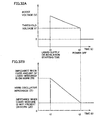
As shown in Fig. 32B, when the liquid medicine is present on horn
oscillator 119, the impedance is relatively high, while it decreases as the
liquid medicine is nebulized, and will be the lowest when the liquid
medicine is not present on horn oscillator 119.
-
Accordingly, at step S37 the boosting potential of horn oscillator 119
is sensed to see if it is at a prescribed value or higher. When boosting
potential is at most the prescribed value (threshold voltage V1), it is
determined that the liquid medicine is not present on horn oscillator 119
(step S38). Then, power supply is turned OFF as indicated in Figs. 31D
and 32A (step S40).
-
In other words, the liquid nebulizing apparatus according to the
present invention includes impedance sensing means for sensing the
impedance of the oscillator (step S37) and oscillator stopping means for
stopping the oscillation of the oscillator in response to the impedance
becoming at most the prescribed value (step S40). Thus, the oscillation of
horn oscillator 119 can be stopped in response to the absence of the liquid
medicine to be nebulized on mesh member 120, suppressing unnecessary
power consumption and attaining a long life of horn oscillator 119.
-
Next, an operation will be described in which an inhalation sensing
is performed referring to Figs. 33A-33D, Figs. 34A and 34B.
-
In an example shown in Fig. 33A, the liquid medicine is measured at
step S 10 in a same manner as in the example above, and thereafter the
'inhalation of a patient is sensed at step 520. The inhalation of the patient.
is sensed by the inhalation sensor 156 above. As shown in Fig. 33C, in
response to sensing the inhalation of the patient (step S21), the power
supply is turned ON (step S22), and the spring is released from the latch by
the solenoid and the like (step S23) and thus extended (step S24),
transferring the liquid medicine to nebulizing part 127 (step S30). In other
words, in response to sensing the inhalation of the patient by inhalation
sensor 156, the liquid medicine is supplied to nebulizing part 127.
-
As shown in Fig. 33A, the liquid medicine is nebulized after being
transferred to nebulizing part 127, and the liquid medicine thus nebulized is
sprayed at step S40. The spraying of the medicine is performed in the same
manner as in the example shown in Figs. 31A-31D. Specifically, as shown
in Fig. 33D, it is performed through each of the following steps: boosting the
cell potential by constant current boosting circuit 153 (step S41); sensing the
current passing through horn oscillator 119 (step S42); constant current-driving
horn oscillator 119 (step S43); and sensing of boosted potential (step
S44).
-
When boosting potential becomes at most the prescribed value
(threshold value V1) as shown in Fig. 34A, it is determined that the liquid
medicine to be nebulized is absent on mesh member 120 (step S45), and the
power supply is turned OFF (step S50). Thus, in response to the absence of
the liquid medicine to be nebulized on mesh member 120, the oscillation of
horn oscillator 119 can be stopped.
-
Next, another example of an operation in which the inhalation
sensing is performed will be described, referring to Figs. 35A-35D.
-
As shown in Fig. 35A, the liquid medicine is measured (step S10),
and then transferred to nebulizing part 127 (step S20). The manner of
measuring liquid medicine is the same as in the example shown in Figs.
33A-33D, and a manner of transferring the liquid medicine to nebulizing
part 127 is the same as in the example shown in Figs. 34A and 34B.
-
Next, the inhalation of the patient is sensed (step S30). As shown
in Fig. 35D, the inhalation of the patient is sensed by inhalation sensor 156
(step S31), and in response to the inhalation of the patient, the power supply
is turned ON (step S32). In other words, the nebulizing operation of the
liquid by nebulizing part 127 is initiated in response to sensing the
inhalation of the patient by inhalation sensor 156.
-
Then, as in the case shown in Figs. 33A-33D, the cell potential is
boosted (step S33), the current passing through horn oscillator 119 is sensed
(step S34), horn oscillator 119 is constant-current driven (step S35), and the
boosting potential is sensed (step S36) and when the boosting potential
becomes at most a prescribed value (threshold voltage V1) as shown in Figs.
34A, B, it is determined that the liquid medicine to be nebulized is absent on
mesh member 120 (step S37) and the power supply is turned OFF (step S50).
-
According to the present embodiment, as compared to Japanese
Patent National Publication No. 8-502689, the lifetime of the cell or the
oscillator can be extended, and also as compared to WO00/66277, the
amount of medicine wasted can be reduced. In the following, these features
will be described.
-
The invention described in Japanese Patent National Publication No.
8-502689, is an apparatus for nebulizing liquid by vibrating a thin film, in
which the thin film is vibrated for a period longer than the period needed for
nebulizing a prescribed amount of the liquid, in order to nebulize of all the
prescribed amount of the liquid..
-
Undesirably, by vibrating the thin film for a long period, not only the
lifetime of the cell for vibrating the thin film is shortened, but also not only
the lifetime of the oscillator is shortened due to the oscillator being vibrated
with no load.
-
In contrast thereto, since the present embodiment includes liquid
supply sensing means 160 and nebulizing operation initiation means 151,
the nebulizing operation of the liquid can be automatically initiated at a
desired time before or after the liquid supply to nebulizing part 127 is
started. Thus, when employing an oscillator for nebulizing the liquid, the
driving period in a unloaded state can be reduced, suppressing unnecessary
power consumption and extending the life of the oscillator. Additionally,
by oscillating the oscillator in advance, just before nebulizing part 127 is
supplied with the liquid, even when the liquid supply amount from
measuring chamber 109 varies, the load of the oscillator may not be
increased excessively and continuous spraying may be attained.
-
Additionally, since the present embodiment includes the impedance
sensing means (step S37) and the oscillator stopping means (step S40), the
oscillation of the oscillator can be stopped in response to the absence of the
liquid on mesh member 120. Thus, the unnecessary power consumption
can be suppressed and the driving of the oscillator in unloaded state can be
avoided, extending the life of the oscillator.
-
Further, in the WO00/66277 above, if the nebulizing part is to be
provided with the liquid medicine manually, then the user wishing to inhale
the liquid medicine must transfer the liquid medicine to nebulizing part
manually, nebulizing and spraying the liquid medicine, and then the user
can inhale it. This results in the shift between the timing of spraying the
nebulized liquid medicine and the timing of the user's inhalation, and thus
the liquid medicine cannot be taken properly. In special, when a small
amount of the liquid medicine is to be inhaled, much medicine is wasted by
the shift in the timing of spraying and the inhalation.
-
In contrast thereto, since the present embodiment includes the
inhalation sensing means (inhalation sensor 156), the nebulizing operation
of the liquid or the liquid supply to the nebulizing part can be performed in
accordance with the inhalation of the patient. Thus, the shift in the timing
of spraying and the user's inhalation may be smaller, reducing the amount
of the medicine not being inhaled by the user and thus wasted.
(Fifth Embodiment)
-
Next, referring to Figs. 40-44, a fifth embodiment of the present
invention will be described.
-
As shown in Figs. 40 and 41, the fifth embodiment is different from
the third embodiment in that a spiral spring is used for lever spring 216 in
piston driving part 126 for driving a piston (not shown).
-
Piston driving part 126 includes push rod 114b, wind up lever 115,
release lever 117, lever plate 128, release string 135, E-ring 201, switch
lever 202, lever shaft 214, and lever spring 216.
-
Push rod 114b has engaging protruding part 114d and rack 114c,
being slidably supported by a guide 101c provided to housing 101. Lever
plate 128 has a pinion 128a engaging with rack 114c of push rod 114b, and
fitted rotatably to a cylindrical part 101a provided to housing 101. Wind up
lever 115 has an operation part 115b that can be manually operated, and
engaging protruding part 115c that can be engaged with the recess part
128b of lever plate 128.
-
Lever shaft 214 is inserted into a perforation hole of cylindrical part
101a from the inside of housing 101, thereby passing through each hole of
lever plate 128 and wind up lever 115, and being fitted with E-ring 201 at its
tip protruding from wind up lever 115. Additionally, this lever shaft 24
also passes through switch lever 202, whereby switch lever 202 rotates with
lever shaft 214. At the lower end of this lever shaft 214, a lever spring 216
formed of spiral spring or the like is provided.
-
As shown in Fig. 42, lever spring 216 is supported at its inner
periphery edge being sandwiched by separating part 214a of lever shaft 214,
and at its outer periphery edge being supported by hanging on lib part 101d
provided to inside of housing 101.
-
Release lever 117 has lock hook 125 that can be inserted in a hole
provided in lever plate 128, and biased upward by release spring 135.
-
A battery unit 108a can be inserted into housing 101 from the lower
side of lever spring 216, and housing 101 may be closed by a bottom cover
unit 101b after inserting battery unit 108a into housing 101.
-
Piston drive part 126 thus structured can drive piston by the
engagement of protrusion part 114d of push rod 114b and the hole of
coupling rod 133.
-
The rest of the configuration is substantially the same as in the third
embodiment described above, therefore the identical members are given
identical reference characters, and description thereof will not be repeated.
-
Next, referring to Figs. 43 and 44, the operation of the liquid
nebulizing apparatus according to the present embodiment will be
described.
-
From the initial state shown in Fig. 43, the operation part 115b of
wind up lever 115 is turned manually to left, (counterclockwise) to turn the
wind up lever 115 by a prescribed angle. Thus, lever plate 128 is turned,
with push rod 114b and coupling rod 113 sliding to right side, and the piston
(not shown) moving to the right side. At this time, the movement of lever
shaft 214 winds up lever spring 216 formed of spiral spring, and a biasing
force that forces wind up lever 115 to turn to right (clockwise) is generated.
-
As the piston moves to the right side by a prescribed amount or more,
the liquid medicine is transferred from reservoir chamber (not shown) to the
measuring chamber (not shown), as in the second and third embodiments.
At this time, the liquid supply port (not shown) is closed by the discharge
valve (not shown).
-
As wind up lever 115 is turned by a prescribed amount, the biasing
force of release spring 135 inserts lock hook 125 into hole 128c provided to
lever plate 128 as shown in Fig. 44, whereby the locked state is attained in
which the piston and other parts are locked at a prescribed position.
-
Next, by pushing down the release lever 117, lock hook 125
disengages from hole 128c provided to lever plate 128, releasing the locked
state of lever plate 128 and lock hook 125. Thus, the biasing force of lever
spring 216 that has been wound-up turns lever plate 128 to right (clockwise),
push rod 114b and coupling rod 133 sliding to the left side.
-
As above, by pushing the piston (not shown) by the biasing force of
lever spring 216, the liquid medicine in the measuring chamber (not shown)
can be pressed by the piston (not shown) with an approximately constant
force as in the second and third embodiments. Accordingly, as in the
second and third embodiments, the nebulizing part 127 can be supplied with
liquid medicine.
-
The manner of the fourth embodiment can be applied to the fifth
embodiment as well.
-
In the present embodiment, as in the second and third embodiments,
since the piston can be pushed by the biasing force of lever spring 216, the
piston can be driven at a constant rate.
-
Further, the liquid nebulizing apparatus according to the present
embodiment can realize nebulization by constant amount easily, while
avoiding scattering of the liquid medicine in nebulizing part 127 and
keeping the size of the apparatus smaller, as compared to the second and
third embodiments. In the following, these features will be described.
-
Referring to Fig. 45, normally in a spring, force applied on a spring F
and displacement amount X are directionally proportional, and gradient of a
straight line indicating the relationship between them will be a spring
constant. Here, having a large spring constant, the difference between a
force F applied on the spring in wound-up state (the spring being most
compressed) and a force F applied on the spring in a state where piston 112
is fully pushed (the spring being most extended) will be large. The
difference in the force F is directly proportional to the difference in the rate
of the spring pushing the piston 112. Specifically, at the position in
wound-up state (the spring being most compressed), the rate of the spring
pushing the piston 112 is high, and in a state where piston 112 is fully
pushed (the spring being most extended), the rate of the spring pushing
piston 112 is lower than that, and thus the amount of changes in the rate
becomes large. Accordingly, considering the mass-production of the liquid
nebulizing apparatus according to the present embodiment, the variations
resulted from individual differences of the springs may hinder to realize the
nebulization by a constant amount.
-
Note that, "the amount of changes in the rate" is sufficiently smaller
than in the first embodiment employing manual operation, and thus it can
substantially be considered as a constant rate.
-
The minimum force required as force F applied on the spring in the
state where piston 112 is fully pushed must be large enough to sufficiently
push discharge valve 113 down against valve spring 118 to push out the
liquid medicine from the measuring chamber 109 through liquid supply port
110. Accordingly, when the spring constant is large, larger force F is
applied on a spring that is fully wound-up, and the rate the spring pushing
the piston 112 will become higher accordingly. Hence, discharge valve 113
is pushed by small amount and the liquid flowing back to ampoule 104 from
measuring chamber 109 becomes smaller by that amount. As a result, a
phenomenon arises that the liquid amount to be supplied to the nebulizing
part is increased. This phenomenon largely fluctuates due to the
individual difference of spring, the deterioration of the parts, and variations
in the viscosity of the liquid medicine, and thus hinders to realize the
nebulization by a constant amount.
-
Further, with a larger spring constant, the rate of the spring
pushing piston 112 will be faster where piston 112 moves past liquid
transfer route 104a that communicates to ampoule 104, whereby the liquid
medicine is transferred to nebulizing part 127 at high rate, inviting the
scattering of the liquid medicine in nebulizing part 127. Hence, it also
hinders the nebulization at a constant amount.
-
If a spring with a smaller spring constant is employed, the difference
in the rate of the spring pushing piston 122 becomes smaller and thus the
nebulization by a constant amount is facilitated, and the liquid medicine
will not be scattered in nebulizing part 127. In this case, however,
increasing the force by which a spring pushes piston 112 will increase the
displacement amount X of the spring, the length of the overall spring must
be increased. Therefore, when a coil spring is employed for piston spring
116 as in the second and third embodiments, since the size is increased in
the longitudinal direction of the helical coil spring, it will be difficult to keep
the apparatus compact.
-
In contrast thereto, according to the present embodiment, a spiral
spring is employed as lever spring 126. In order to increase the length of
the spiral spring, it should be increased in a spiral direction. On the other
hand, when increasing in the spiral direction, since the length can be
increased in the circumferential direction, the size of spiral spring can be
maintained smaller than the coil spring that must be increased in the
longitudinal direction. Hence, the liquid nebulizing apparatus according to
the present embodiment employing a spiral spring is more suitable for
maintaining the apparatus in compact size as compared to the configuration
of the second and third embodiments.
-
As above, by employing a spiral spring having a smaller spring
constant as lever spring 216, the liquid nebulizing apparatus according to
the present embodiment can easily attain the nebulization by a constant
amount, avoiding the scattering of the liquid medicine at nebulizing part
127, in a compact structure.
-
Although the present invention has been described referring to the
embodiments, it is clearly understood that the same is by way of illustration
and example only and is not to be taken by way of limitation, the spirit and
scope of the present invention being limited only by the terms of the
appended claims, including all modifications in the equivalents of the claims
and in the scope of the claims.
Industrial Applicability
-
The present invention can advantageously be applied to a liquid
nebulizing apparatus for stabilizing the liquid amount being transferred to
a nebulizing part for stabilizing the nebulization, and for realizing it at low
costs.