EP1343585B1 - Abdeckungsanordnung für mikrotestplatte - Google Patents
Abdeckungsanordnung für mikrotestplatte Download PDFInfo
- Publication number
- EP1343585B1 EP1343585B1 EP01991190A EP01991190A EP1343585B1 EP 1343585 B1 EP1343585 B1 EP 1343585B1 EP 01991190 A EP01991190 A EP 01991190A EP 01991190 A EP01991190 A EP 01991190A EP 1343585 B1 EP1343585 B1 EP 1343585B1
- Authority
- EP
- European Patent Office
- Prior art keywords
- microplate
- cover
- tabs
- assembly
- extending
- Prior art date
- Legal status (The legal status is an assumption and is not a legal conclusion. Google has not performed a legal analysis and makes no representation as to the accuracy of the status listed.)
- Expired - Lifetime
Links
- 239000000463 material Substances 0.000 claims description 7
- 239000003566 sealing material Substances 0.000 abstract description 5
- 238000013537 high throughput screening Methods 0.000 abstract description 3
- 238000007789 sealing Methods 0.000 description 9
- 239000000853 adhesive Substances 0.000 description 2
- 230000001070 adhesive effect Effects 0.000 description 2
- 230000000712 assembly Effects 0.000 description 2
- 238000000429 assembly Methods 0.000 description 2
- 231100001261 hazardous Toxicity 0.000 description 2
- 238000000034 method Methods 0.000 description 2
- 238000010998 test method Methods 0.000 description 2
- 238000012360 testing method Methods 0.000 description 2
- 229920006385 Geon Polymers 0.000 description 1
- MWCLLHOVUTZFKS-UHFFFAOYSA-N Methyl cyanoacrylate Chemical compound COC(=O)C(=C)C#N MWCLLHOVUTZFKS-UHFFFAOYSA-N 0.000 description 1
- 239000004743 Polypropylene Substances 0.000 description 1
- 239000004820 Pressure-sensitive adhesive Substances 0.000 description 1
- 229910000831 Steel Inorganic materials 0.000 description 1
- 239000004830 Super Glue Substances 0.000 description 1
- 229920001070 Techron Polymers 0.000 description 1
- 229920006362 Teflon® Polymers 0.000 description 1
- 238000004873 anchoring Methods 0.000 description 1
- 238000013459 approach Methods 0.000 description 1
- 238000000576 coating method Methods 0.000 description 1
- 238000005260 corrosion Methods 0.000 description 1
- 230000007797 corrosion Effects 0.000 description 1
- 238000012864 cross contamination Methods 0.000 description 1
- 238000013461 design Methods 0.000 description 1
- 239000011159 matrix material Substances 0.000 description 1
- 238000009828 non-uniform distribution Methods 0.000 description 1
- 238000007747 plating Methods 0.000 description 1
- 229920001084 poly(chloroprene) Polymers 0.000 description 1
- 229920001200 poly(ethylene-vinyl acetate) Polymers 0.000 description 1
- -1 polypropylene Polymers 0.000 description 1
- 229920001155 polypropylene Polymers 0.000 description 1
- 229910001220 stainless steel Inorganic materials 0.000 description 1
- 239000010935 stainless steel Substances 0.000 description 1
- 239000010959 steel Substances 0.000 description 1
- 238000003466 welding Methods 0.000 description 1
Images


Classifications
-
- B—PERFORMING OPERATIONS; TRANSPORTING
- B01—PHYSICAL OR CHEMICAL PROCESSES OR APPARATUS IN GENERAL
- B01L—CHEMICAL OR PHYSICAL LABORATORY APPARATUS FOR GENERAL USE
- B01L3/00—Containers or dishes for laboratory use, e.g. laboratory glassware; Droppers
- B01L3/50—Containers for the purpose of retaining a material to be analysed, e.g. test tubes
- B01L3/508—Containers for the purpose of retaining a material to be analysed, e.g. test tubes rigid containers not provided for above
- B01L3/5085—Containers for the purpose of retaining a material to be analysed, e.g. test tubes rigid containers not provided for above for multiple samples, e.g. microtitration plates
- B01L3/50853—Containers for the purpose of retaining a material to be analysed, e.g. test tubes rigid containers not provided for above for multiple samples, e.g. microtitration plates with covers or lids
-
- B—PERFORMING OPERATIONS; TRANSPORTING
- B01—PHYSICAL OR CHEMICAL PROCESSES OR APPARATUS IN GENERAL
- B01J—CHEMICAL OR PHYSICAL PROCESSES, e.g. CATALYSIS OR COLLOID CHEMISTRY; THEIR RELEVANT APPARATUS
- B01J2219/00—Chemical, physical or physico-chemical processes in general; Their relevant apparatus
- B01J2219/00274—Sequential or parallel reactions; Apparatus and devices for combinatorial chemistry or for making arrays; Chemical library technology
- B01J2219/00277—Apparatus
- B01J2219/00279—Features relating to reactor vessels
- B01J2219/00306—Reactor vessels in a multiple arrangement
- B01J2219/00313—Reactor vessels in a multiple arrangement the reactor vessels being formed by arrays of wells in blocks
- B01J2219/00315—Microtiter plates
- B01J2219/00317—Microwell devices, i.e. having large numbers of wells
-
- B—PERFORMING OPERATIONS; TRANSPORTING
- B01—PHYSICAL OR CHEMICAL PROCESSES OR APPARATUS IN GENERAL
- B01J—CHEMICAL OR PHYSICAL PROCESSES, e.g. CATALYSIS OR COLLOID CHEMISTRY; THEIR RELEVANT APPARATUS
- B01J2219/00—Chemical, physical or physico-chemical processes in general; Their relevant apparatus
- B01J2219/00274—Sequential or parallel reactions; Apparatus and devices for combinatorial chemistry or for making arrays; Chemical library technology
- B01J2219/00583—Features relative to the processes being carried out
- B01J2219/00585—Parallel processes
- B01J2219/00587—High throughput processes
-
- B—PERFORMING OPERATIONS; TRANSPORTING
- B01—PHYSICAL OR CHEMICAL PROCESSES OR APPARATUS IN GENERAL
- B01J—CHEMICAL OR PHYSICAL PROCESSES, e.g. CATALYSIS OR COLLOID CHEMISTRY; THEIR RELEVANT APPARATUS
- B01J2219/00—Chemical, physical or physico-chemical processes in general; Their relevant apparatus
- B01J2219/00274—Sequential or parallel reactions; Apparatus and devices for combinatorial chemistry or for making arrays; Chemical library technology
- B01J2219/0068—Means for controlling the apparatus of the process
- B01J2219/00686—Automatic
- B01J2219/00691—Automatic using robots
-
- C—CHEMISTRY; METALLURGY
- C40—COMBINATORIAL TECHNOLOGY
- C40B—COMBINATORIAL CHEMISTRY; LIBRARIES, e.g. CHEMICAL LIBRARIES
- C40B60/00—Apparatus specially adapted for use in combinatorial chemistry or with libraries
- C40B60/14—Apparatus specially adapted for use in combinatorial chemistry or with libraries for creating libraries
Definitions
- the present invention relates generally to the field of microplates and, more specifically, to a microplate cover assembly which provides a removable seal and is compatible with manual or robotic handling systems.
- Microplates are commonly used in a variety of test procedures. During such procedures, it may be desirable or necessary to seal the wells contained in the microplates in order to produce appropriate test conditions, prevent cross-contamination among wells, prevent sample leakage during transportation or storage, or prevent human exposure to hazardous samples. In addition, some test procedures, including high throughput screening, may require a large number (e.g., on the order of hundreds or thousands) of microplates to be handled by robotic equipment. In such an environment, it is essential that the process of engaging or disengaging the microplate's seal does not interfere with the robotic equipment or unduly reduce the throughput of the system.
- the present invention provides a microplate cover assembly which provides a substantially uniform, secure, reliable seal of the microplate's wells, and which is well suited for use with robotic handling systems.
- the assembly includes a layer of sealing material, a pressure plate and a cover.
- the cover is shaped so as to exert a compressive force on the pressure plate when the assembly is engaged with the microplate.
- the pressure plate in turn, disperses the compressive force in a generally uniform manner across the layer of sealing material.
- the cover, pressure plate and sealing layer are preferably attached to each other by adhesive or other type of fastener.
- the cover includes a number of laterally-extending tabs which serve as gripping points for a robotic microplate handling system. Such tabs enable a robotic manipulator to engage the cover with a microplate, disengage the cover, and transport the engaged cover/microplate as a unit.
- the cover may also include a number of downwardly-extending tabs which enable multiple units to be stacked in a stable manner. The embodiment is designed to not obstruct the surfaces of the microplate where barcodes are typically applied.
- the pressure plate may include features for holding the assembly for robotic handling.
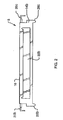
- FIG. 1 shows a microplate cover assembly 2 which may be used to seal wells 6 contained in a microplate 4.
- Microplate 4 is of conventional design and is available from any of a number of commercial sources in any of 24, 96 or 384 well formats, and may include others. It should be understood that the term "microplate” as used herein includes, but is not limited to, shallow well, deepwell, half deepwell and PCR type plates as well as minitube racks. It should also be understood that the present invention is not limited to any particular matrix size.
- a cover 8 is disposed on a pressure plate 10.
- Pressure plate 10 is disposed on a layer of sealing material 12, which in turn is disposed on the top surface of microplate 4.
- Cover 8 includes an angled top surface 16 with a narrow, generally flat portion 18 extending laterally along the central axis of the cover.
- Cover 8 includes sides 14a and 14b which are generally orthogonal to top surface 16. Extending laterally from the edges of top surface 16 are tabs 20a-20d which function as gripping points for a robotic handling system (not shown).
- Each side 14a, 14b includes a generally rectangular aperture, only one of which, 22b, is visible in this figure.
- Such apertures allow side surface 28 of microplate 4 to remain visible when assembly 2 is engaged with the microplate. Thus, identifying marks or bar code labels, which are often located on side surface 28, are not obscured once microplate 4 is sealed.
- such apertures increase the flexibility of sides 14a, 14b, thereby reducing the force necessary to either engage or disengage cover 8 from microplate 4.
- Each side 14a, 14b also includes an inwardly-extending flange, only one of which, 24a, is partially visible.
- Such flanges extend laterally for most of the lengths of sides 14a, 14b and, when cover 8 is engaged with microplate 4, support a bottom edge 30 of microplate 4, keeping the microplate from distorting and anchoring the cover to the microplate.
- each side 14a, 14b also includes a foot, three of which, 26a-26c, are visible in this figure. As described in detail below, feet 26 allow multiple cover assembly 2/microplate 4 units to be stacked one upon another.
- Cover 8 and pressure plate 10 are preferably constructed from stainless steel or conventional spring steels with corrosion resistant plating or coatings.
- Layer 12 is preferably constructed from a material sold under the trademark GEON. It will be apparent to those skilled in the art that a wide variety of other suitable materials may be substituted including Techron, EVA, Neoprene, polypropylene or Teflon® films.
- cover 8, pressure plate 10 and sealing layer 12 are joined together by a mechanical arrangement such as swaged over tabs, spot welding or riveting.
- Pressure plate 10 and sealing layer 12 are preferably joined with a conventional adhesive such as cyano-acrylate or pressure sensitive adhesive suitable for the material being bonded. With its components fastened together, cover assembly 2 may be more easily engaged with and disengaged from microplate 4.
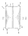
- Tabs 20b and 20c, feet 26b and 26c, and aperture 22b may be more clearly seen in Figure 2, which is a right side elevation of cover 8.
- Tabs 20a-20d may be more clearly seen in Figure 3, which is a top plan view of cover 8.
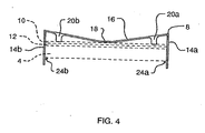
- FIG 4 is a section taken along line 4-4 of Figure 3.
- Microplate 4, pressure plate 10 and sealing layer 12 are shown in phantom as they would generally appear when microplate 4 is sealed. It should be understood that, depending upon the thicknesses of microplate 4, pressure plate 10 and sealing layer 12, as well as the compressive force that is desired, top surface 16 may appear more or less flat than depicted when cover 8 is engaged with microplate 4, either with a plate or without, the sides 14a, 14b remain substantially vertical and consistent in height.
- cover 8 is engaged with and disengaged from microplate 4 by a robotic manipulator (not shown) which grasps tabs 20a and 20b (or, alternatively, tabs 20c and 20d) or, alternatively, with tabs on pressure plate 10, as shown below in Figure 6.
- a robotic manipulator grasps pressure plate 10 and applies a compressive force to cover 8, then grasps tabs 20a, 20b and rotates them slightly in opposite directions so as to force sides 14a, 14b to flex outwardly. This creates sufficient clearance for cover 8 (and, preferably, attached pressure plate 10 and sealing layer 12) to be lowered onto microplate 4 from above.
- the robotic manipulator allows the tabs to counter-rotate to their original positions, causing flanges 24a, 24b to slip under the bottom edge of microplate 4.
- the compressive force on cover 8 is now removed so that cover 8 now exerts a compressive force on pressure plate 10, which disperses that force laterally in a substantially uniform manner, thereby creating a fairly even pressure across sealing layer 12.
- a slight downward force is preferably exerted on the top surface 16 of cover 8.
- a robotic manipulator grasps a pair of adjacent tabs 20 and rotates them slightly so as to clear flanges 24a, 24b from the bottom edge of microplate 4. At that point, cover 8 may be lifted clear from microplate 4.
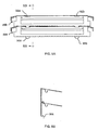
- FIGS 5A and 5B show an alternative embodiment of the present invention.
- cover 28a two feet 30a, 30b extend from the bottom edge of each side of the cover.
- Feet 30a, 30b are shaped and dimensioned to engage with slots 32a, 32b of a second cover 28b, thereby allowing such covers to be stacked in a stable manner.
- FIGS 5C and 5D show a second alternative embodiment of the present invention. Again, two feet 36a, 36b are provided at the bottom edge of each side of cover 34a. Feet 36a, 36b engage with slots 38a, 38b located on a second cover.
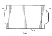
- Figure 6 shows an alternative embodiment of a pressure plate 40 which includes tabs 42a, 42b for robotic attachment, as described above.
Landscapes
- Health & Medical Sciences (AREA)
- Chemical & Material Sciences (AREA)
- Chemical Kinetics & Catalysis (AREA)
- General Health & Medical Sciences (AREA)
- Hematology (AREA)
- Clinical Laboratory Science (AREA)
- Analytical Chemistry (AREA)
- Automatic Analysis And Handling Materials Therefor (AREA)
- Sampling And Sample Adjustment (AREA)
- Packages (AREA)
- Closures For Containers (AREA)
- Casings For Electric Apparatus (AREA)
- Packaging Frangible Articles (AREA)
Claims (8)
- Abdeckungsbaugruppe für eine Mikroplatte, wobei die Baugruppe aufweist:eine Materialschicht (12), die so geformt und bemessen ist, dass sie eine Mehrzahl Öffnungen der Plätze (Wells) der Mikroplatte abnehmbar dicht verschließt;eine Druckplatte (10), die auf der Materialschicht angeordnet ist, um eine Druckkraft in einer allgemein gleichmäßigen Weise über der Schicht zu verteilen;eine Abdeckung (8) mit einer Oberfläche (16) sowie einer ersten und zweiten Seite (14a, 14b), wobei die Oberfläche so geformt ist, dass sie die Druckkraft erzeugt, wenn die Abdeckung mit der Mikroplatte in Eingriff kommt, wobei die erste und zweite Seite jeweils einen Vorsprung (24a, 24b) enthält, um eine Unterkante der Mikroplatte zu tragen;eine Mehrzahl senkrechter Nasen (30a, 30b), die sich von den Vorsprüngen aus nach unten erstrecken; undeine Mehrzahl Öffnungen (32a) in der Abdeckung, die mit den Nasen übereinstimmen, wodurch eine Mehrzahl Abdeckungen gestapelt werden kann, wobei die senkrechten Nasen einer Abdeckung hinunter in die Öffnungen einer darunter befindlichen Abdeckung ragen.
- Abdeckungsbaugruppe nach Anspruch 1, bei der die Oberfläche und die Druckplatte jeweils eine oder mehrere sich in Längsrichtung erstreckende Nasen (20a, 42a) enthalten, die es ermöglichen, dass die Abdeckung durch ein Robotersystem mit der Mikroplatte in Eingriff oder außer Eingriff gebracht wird.
- Abdeckungsbaugruppe nach Anspruch 1, bei der die erste und zweite Seite der Abdeckung Öffnungen enthält, die zumindest Abschnitte der Seitenoberflächen der Mikroplatte sichtbar machen, wenn die Abdeckung mit der Mikroplatte in Eingriff gebracht wird.
- Abdeckungsbaugruppe nach Anspruch 1 mit sich in Längsrichtung von der ersten und zweiten Seite aus erstreckenden Nasen, mittels derer die Abdeckung mit der Mikroplatte außer Eingriff oder in Eingriff gebracht werden kann, indem die Nasen seitlich nach außen oder innen verschoben werden, um die Vorsprünge von den Unterkanten der Mikroplatte weg oder unter diese zu bewegen.
- Abdeckungsbaugruppe nach Anspruch 1, bei der die Abdeckungsoberfläche einen mittleren sich in Längsrichtung erstreckenden ebenen Rillenabschnitt sowie seitliche und ebene Abschnitte enthält, die sich von ihren Innenrändern von der Rille aus nach oben erstrecken, wobei sich die Seiten von den Außenrändern der ebenen Abschnitte aus nach unten erstrecken, wodurch die ebenen Abschnitte und die Rille eine elastische Kraft bereitstellen, die nach unten auf die Druckplatte und nach oben auf die Unterkanten der Mikroplatte wirkt.
- Baugruppe nach Anspruch 1 mit sich in Längsrichtung von der ersten und zweiten Seite aus erstreckenden Nasen, mittels derer die Abdeckung mit der Mikroplatte außer Eingriff oder in Eingriff gebracht werden kann, indem die Nasen seitlich nach außen oder innen verschoben werden, um die Vorsprünge von den Unterkanten der Mikroplatte weg oder unter diese zu bewegen.
- Abdeckungsbaugruppe für eine Mikroplatte, wobei die Baugruppe aufweist:eine Materialschicht (12), die so geformt und bemessen ist, dass sie eine Mehrzahl Öffnungen der Plätze (Wells) der Mikroplatte abnehmbar dicht verschließt;eine Druckplatte (10), die auf der Materialschicht angeordnet ist, um eine Druckkraft in einer allgemein gleichmäßigen Weise über der Schicht zu verteilen; undeine Abdeckung mit einer Oberfläche (16) sowie einer ersten und zweiten Seite (14a, 14b), wobei die Oberfläche einen mittleren sich in Längsrichtung erstreckenden ebenen Rillenabschnitt (18) sowie seitliche ebene Abschnitte enthält, die sich von ihren Innenrändern von der Rille aus nach oben erstrecken, wobei sich die Seiten von den Außenrändern der ebenen Abschnitte aus nach unten erstrecken und Vorsprünge (24a, 24b) enthalten, die sich unterhalb der Unterkanten der Mikroplatte erstrecken; wodurch die ebenen Abschnitte und der Rillenabschnitt eine elastische Kraft bereitstellen, die nach unten auf die Druckplatte und nach oben auf die Unterkanten der Mikroplatte wirkt.
- Baugruppe nach Anspruch 7 mit sich in Längsrichtung von der ersten und zweiten Seite aus erstreckenden Nasen, mittels derer die Abdeckung mit der Mikroplatte außer Eingriff oder in Eingriff gebracht werden kann, indem die Nasen seitlich nach außen oder innen verschoben werden, um die Vorsprünge von den Unterkanten der Mikroplatte weg oder unter diese zu bewegen.
Applications Claiming Priority (3)
| Application Number | Priority Date | Filing Date | Title |
|---|---|---|---|
| US09/740,624 US6896848B1 (en) | 2000-12-19 | 2000-12-19 | Microplate cover assembly |
| US740624 | 2000-12-19 | ||
| PCT/US2001/048714 WO2002049760A2 (en) | 2000-12-19 | 2001-12-12 | Microplate cover assembly |
Publications (2)
| Publication Number | Publication Date |
|---|---|
| EP1343585A2 EP1343585A2 (de) | 2003-09-17 |
| EP1343585B1 true EP1343585B1 (de) | 2006-07-12 |
Family
ID=24977356
Family Applications (1)
| Application Number | Title | Priority Date | Filing Date |
|---|---|---|---|
| EP01991190A Expired - Lifetime EP1343585B1 (de) | 2000-12-19 | 2001-12-12 | Abdeckungsanordnung für mikrotestplatte |
Country Status (7)
| Country | Link |
|---|---|
| US (1) | US6896848B1 (de) |
| EP (1) | EP1343585B1 (de) |
| JP (1) | JP2004530862A (de) |
| AT (1) | ATE332747T1 (de) |
| AU (1) | AU2002230932A1 (de) |
| DE (1) | DE60121467T2 (de) |
| WO (1) | WO2002049760A2 (de) |
Families Citing this family (23)
| Publication number | Priority date | Publication date | Assignee | Title |
|---|---|---|---|---|
| US7125522B2 (en) | 2001-11-19 | 2006-10-24 | Becton, Dickinson And Company | Multiwell apparatus |
| AU2002315964A1 (en) * | 2002-07-15 | 2004-02-02 | Avantium International B.V. | A system for the preparation of multiple solid state samples, in particular for spectroscopic and microscopic analysis |
| US7055695B2 (en) * | 2003-06-02 | 2006-06-06 | Caliper Life Sciencee, Inc. | Container providing a controlled hydrated environment |
| US20040258563A1 (en) | 2003-06-23 | 2004-12-23 | Applera Corporation | Caps for sample wells and microcards for biological materials |
| US20060024209A1 (en) * | 2004-07-30 | 2006-02-02 | Agnew Brian J | Apparatus, methods, and kits for assaying a plurality of fluid samples for a common analyte |
| US20060024204A1 (en) * | 2004-08-02 | 2006-02-02 | Oldenburg Kevin R | Well plate sealing apparatus and method |
| WO2007053853A2 (en) | 2005-11-01 | 2007-05-10 | Nexus Biosystems, Inc. | System and method for simultaneous capping/de-capping of storage containers in an array |
| CN101970115B (zh) * | 2006-01-23 | 2014-03-12 | 纽克塞斯生物系统公司 | 用于储藏、取回和管理样品的自动化系统 |
| US10697987B2 (en) | 2006-01-23 | 2020-06-30 | Brooks Automation, Inc. | Automated system for storing, retrieving and managing samples |
| US20070175897A1 (en) * | 2006-01-24 | 2007-08-02 | Labcyte Inc. | Multimember closures whose members change relative position |
| EP1872855A1 (de) * | 2006-06-27 | 2008-01-02 | F.Hoffmann-La Roche Ag | Platte zum Äquilibrieren einer Flüssigkeit |
| EP1872856A1 (de) * | 2006-06-27 | 2008-01-02 | F.Hoffmann-La Roche Ag | Gleichgewichtsvorrichtung |
| US8221697B2 (en) | 2007-01-12 | 2012-07-17 | Nichols Michael J | Apparatus for lidding or delidding microplate |
| US7767154B2 (en) * | 2007-01-12 | 2010-08-03 | HighRes Biosolutions, Inc. | Microplate kit |
| AU2008226410A1 (en) | 2007-03-09 | 2008-09-18 | Nexus Biosystems, Inc. | Device and method for removing a peelable seal |
| FI20075191A0 (fi) | 2007-03-23 | 2007-03-23 | Bioinnovations Oy | Väline ja menetelmä analyysiä varten |
| US20080293157A1 (en) * | 2007-05-24 | 2008-11-27 | Gerald Frederickson | Apparatus and method of performing high-throughput cell-culture studies on biomaterials |
| DE102008008256A1 (de) | 2007-10-08 | 2009-04-09 | M2P-Labs Gmbh | Mikroreaktor |
| US20100008828A1 (en) * | 2008-07-11 | 2010-01-14 | Bambi Lyn Cahilly | Well plate seal structure |
| JP5680950B2 (ja) * | 2009-12-10 | 2015-03-04 | エフ.ホフマン−ラ ロシュ アーゲーF. Hoffmann−La Roche Aktiengesellschaft | マルチウェル・プレート及び蓋体 |
| US8808644B2 (en) * | 2012-08-20 | 2014-08-19 | Biochemical Diagnostics, Inc. | Methods for dispensing fluids into microplates utilizing microwell covers |
| USD710024S1 (en) * | 2013-03-14 | 2014-07-29 | Bio-Rad Laboratories, Inc. | Microplate |
| CN118272183A (zh) * | 2022-12-31 | 2024-07-02 | 深圳市新产业生物医学工程股份有限公司 | 扩增板组件及其状态检测方法 |
Family Cites Families (87)
| Publication number | Priority date | Publication date | Assignee | Title |
|---|---|---|---|---|
| US3302854A (en) | 1961-09-26 | 1967-02-07 | Sweetheart Plastics | Cluster of covers |
| US3206017A (en) | 1962-01-09 | 1965-09-14 | Sweetheart Plastics | Cluster of container covers |
| US3366265A (en) | 1966-05-09 | 1968-01-30 | Best Plastics Inc | Multiple unit package |
| US3674396A (en) * | 1970-09-21 | 1972-07-04 | Miles Lab | Biological specimen processing and embedding apparatus |
| USRE28165E (en) * | 1973-03-21 | 1974-09-17 | Biological specimen processing and embedding apparatus | |
| US3883398A (en) * | 1973-05-07 | 1975-05-13 | Bellco Glass Inc | Microculture slide chamber |
| US3858752A (en) | 1974-02-04 | 1975-01-07 | Plastics Research Corp | Container having improved resealable closure system |
| US3910410A (en) | 1974-03-19 | 1975-10-07 | Continental Can Co | Resealable package |
| US4038149A (en) * | 1975-12-31 | 1977-07-26 | Linbro Scientific, Inc. | Laboratory trays with lockable covers |
| US4246339A (en) | 1978-11-01 | 1981-01-20 | Millipore Corporation | Test device |
| US4292273A (en) | 1979-06-29 | 1981-09-29 | Data Packaging Corporation | Radioimmunoassay plate |
| US4284202A (en) | 1979-10-19 | 1981-08-18 | Hardigg Industries, Inc. | Reusable container |
| AU536262B2 (en) * | 1979-12-03 | 1984-05-03 | Kenji Nakamura | Resealable dispenser container |
| DE3037826C2 (de) | 1980-10-07 | 1985-06-05 | Drägerwerk AG, 2400 Lübeck | Probenahmeröhrchen mit Verschlußkappen |
| US4495289A (en) | 1981-03-17 | 1985-01-22 | Data Packaging Corporation | Tissue culture cluster dish |
| US4391780A (en) | 1981-07-06 | 1983-07-05 | Beckman Instruments, Inc. | Container for sample testing |
| US4626509A (en) | 1983-07-11 | 1986-12-02 | Data Packaging Corp. | Culture media transfer assembly |
| US4704255A (en) | 1983-07-15 | 1987-11-03 | Pandex Laboratories, Inc. | Assay cartridge |
| US4493815A (en) | 1983-07-28 | 1985-01-15 | Bio-Rad Laboratories, Inc. | Supporting and filtering biochemical test plate assembly |
| US4473168A (en) | 1983-09-28 | 1984-09-25 | The Procter & Gamble Company | Overcap having a resiliently deformable member for resealing dispensing aperture in integral container lid |
| DE3407043A1 (de) * | 1984-02-27 | 1985-09-05 | Gregor Hofbauer GmbH, 8033 Planegg | Verpackungsbehaelter |
| US4657867A (en) * | 1984-11-01 | 1987-04-14 | Becton, Dickinson And Company | Multiwell tissue culture assembly with features for reduced media evaporation |
| US4569438A (en) | 1985-02-04 | 1986-02-11 | Revlon, Inc. | Container having fluid-tight seal |
| US5038852A (en) | 1986-02-25 | 1991-08-13 | Cetus Corporation | Apparatus and method for performing automated amplification of nucleic acid sequences and assays using heating and cooling steps |
| US4680269A (en) | 1985-04-15 | 1987-07-14 | Pasco Laboratories, Inc. | Method and apparatus for preventing cross-contamination of biochemical test wells in a microtiter test plate |
| US5047215A (en) | 1985-06-18 | 1991-09-10 | Polyfiltronics, Inc. | Multiwell test plate |
| US4948442A (en) | 1985-06-18 | 1990-08-14 | Polyfiltronics, Inc. | Method of making a multiwell test plate |
| US4847050A (en) | 1985-07-22 | 1989-07-11 | E. I. Du Pont De Nemours And Company | Resealable lid structure for a container |
| US4777021A (en) | 1986-04-25 | 1988-10-11 | Richard K. Wertz | Manifold vacuum device for biochemical and immunological uses |
| US5110556A (en) | 1986-10-28 | 1992-05-05 | Costar Corporation | Multi-well test plate |
| US4895706A (en) | 1986-10-28 | 1990-01-23 | Costar Corporation | Multi-well filter strip and composite assemblies |
| US4948564A (en) | 1986-10-28 | 1990-08-14 | Costar Corporation | Multi-well filter strip and composite assemblies |
| DE3722563A1 (de) | 1987-07-08 | 1989-01-19 | Andreas Szabados | Filtrationseinheit mit druckausgleich |
| US4902481A (en) | 1987-12-11 | 1990-02-20 | Millipore Corporation | Multi-well filtration test apparatus |
| US5011779A (en) | 1988-01-21 | 1991-04-30 | Long Island Jewish Medical Center | Apparatus for rapid deposition of test samples on an absorbent support |
| DE3818614A1 (de) * | 1988-06-01 | 1989-12-07 | Messerschmitt Boelkow Blohm | Mikrobehaelter |
| US5188963A (en) | 1989-11-17 | 1993-02-23 | Gene Tec Corporation | Device for processing biological specimens for analysis of nucleic acids |
| US5108704A (en) | 1988-09-16 | 1992-04-28 | W. R. Grace & Co.-Conn. | Microfiltration apparatus with radially spaced nozzles |
| US4927604A (en) | 1988-12-05 | 1990-05-22 | Costar Corporation | Multiwell filter plate vacuum manifold assembly |
| US5056427A (en) * | 1989-03-15 | 1991-10-15 | Seiko Instruments Inc. | Sealing of cavity on reagent tray |
| US4912057A (en) | 1989-06-13 | 1990-03-27 | Cancer Diagnostics, Inc. | Cell chamber for chemotaxis assay |
| US5219528A (en) | 1989-07-28 | 1993-06-15 | Pierce Chemical Company | Apparatus for rapid immunoassays |
| US5065885A (en) | 1990-02-09 | 1991-11-19 | Scaroni F.Lli S.P.A. | Airtight container |
| US5076933A (en) | 1990-06-29 | 1991-12-31 | Coulter Corporation | Process and apparatus for removal of dna and viruses |
| US5141719A (en) | 1990-07-18 | 1992-08-25 | Bio-Rad Laboratories, Inc. | Multi-sample filtration plate assembly |
| SE9002579D0 (sv) | 1990-08-07 | 1990-08-07 | Pharmacia Ab | Method and apparatus for carrying out biochemical reactions |
| US5130105A (en) | 1990-10-23 | 1992-07-14 | The United States Of America As Represented By The Administrator Of The National Aeronautics And Space Administration | Protein crystal growth tray assembly |
| US5282543A (en) * | 1990-11-29 | 1994-02-01 | The Perkin Elmer Corporation | Cover for array of reaction tubes |
| US5094355A (en) | 1990-12-20 | 1992-03-10 | Mobil Oil Corporation | Hinged-lid food container with sealable compartments employing front and side latching means |
| US5178779A (en) | 1991-01-02 | 1993-01-12 | Rohm And Haas Company | Device for protecting against chemical splashing due to breakage of disk filters |
| US5133939A (en) | 1991-03-21 | 1992-07-28 | Barnstead Thermolyne Corporation | Test tube holder and tray assembly |
| US5108603A (en) * | 1991-04-04 | 1992-04-28 | Life Technologies, Inc. | Self-contained vacuum clamped multi-sample media filtration apparatus and method |
| US5112574A (en) | 1991-04-26 | 1992-05-12 | Imanigation, Ltd. | Multititer stopper array for multititer plate or tray |
| US6258325B1 (en) * | 1993-04-19 | 2001-07-10 | Ashok Ramesh Sanadi | Method and apparatus for preventing cross-contamination of multi-well test plates |
| US5342581A (en) | 1993-04-19 | 1994-08-30 | Sanadi Ashok R | Apparatus for preventing cross-contamination of multi-well test plates |
| US5961926A (en) | 1993-09-27 | 1999-10-05 | Packard Instrument Co., Inc. | Microplate assembly and method of preparing samples for analysis in a microplate assembly |
| AU2122395A (en) * | 1994-04-04 | 1995-10-23 | Ashok R. Sanadi | Method and apparatus for preventing cross-contamination of multi-well test plates |
| US5427742A (en) * | 1994-04-26 | 1995-06-27 | Holland; Wayne | Tissue processing cassette |
| US6204051B1 (en) * | 1994-05-04 | 2001-03-20 | Oxyrase, Inc. | Apparatus and method for growing anaerobic microorganisms |
| SE9402076D0 (sv) * | 1994-06-13 | 1994-06-13 | Vincenzo Vassarotti | Method for concentrating or washing macromolecules in a solution and device for carrying out said mehod |
| US5604130A (en) * | 1995-05-31 | 1997-02-18 | Chiron Corporation | Releasable multiwell plate cover |
| TW436777B (en) | 1995-09-29 | 2001-05-28 | Matsushita Electric Industrial Co Ltd | A method and an apparatus for reproducing bitstream having non-sequential system clock data seamlessly therebetween |
| US5856176A (en) * | 1996-03-29 | 1999-01-05 | Corning Incorporated | Culture dish |
| DE59700348D1 (de) * | 1996-06-15 | 1999-09-23 | Dbb Fuel Cell Engines Gmbh | Reformierungsreaktor, insbesondere zur Wasserdampfreformierung von Methanol |
| US5665247A (en) | 1996-09-16 | 1997-09-09 | Whatman Inc. | Process for sealing microplates utilizing a thin polymeric film |
| US6027694A (en) | 1996-10-17 | 2000-02-22 | Texperts, Inc. | Spillproof microplate assembly |
| US5817509A (en) * | 1997-03-19 | 1998-10-06 | Becton Dickinson And Company | Culture vessel assembly |
| US5863792A (en) * | 1997-03-19 | 1999-01-26 | Becton Dickson And Company | Culture vessel assembly |
| US5882922A (en) * | 1997-03-19 | 1999-03-16 | Becton Dickinson And Company | Culture vessel assembly |
| US5780294A (en) * | 1997-03-19 | 1998-07-14 | Becton Dickinson And Company | Culture vessel assembly |
| US6426050B1 (en) * | 1997-05-16 | 2002-07-30 | Aurora Biosciences Corporation | Multi-well platforms, caddies, lids and combinations thereof |
| US6171780B1 (en) * | 1997-06-02 | 2001-01-09 | Aurora Biosciences Corporation | Low fluorescence assay platforms and related methods for drug discovery |
| US5854065A (en) * | 1997-10-06 | 1998-12-29 | Becton Dickinson And Company | Microorganism sampling device |
| US20010007642A1 (en) | 1998-03-03 | 2001-07-12 | Marc Feiglin | Sealing apparatus for use with microplates |
| US6126191A (en) * | 1998-03-16 | 2000-10-03 | General Motors Corporation | Air bag module assembly |
| US5928934A (en) * | 1998-04-14 | 1999-07-27 | Mccormick; James B. | Apparatus and method for preparing small tissue samples for histological examination |
| US6436351B1 (en) * | 1998-07-15 | 2002-08-20 | Deltagen Research Laboratories, L.L.C. | Microtitre chemical reaction system |
| US6159368A (en) * | 1998-10-29 | 2000-12-12 | The Perkin-Elmer Corporation | Multi-well microfiltration apparatus |
| GB2344420B (en) | 1998-12-01 | 2001-08-01 | Advanced Biotech Ltd | Improved sealing mat for multiwell plates |
| US6486401B1 (en) * | 1999-02-22 | 2002-11-26 | Tekcel, Inc. | Multi well plate cover and assembly |
| US6558628B1 (en) | 1999-03-05 | 2003-05-06 | Specialty Silicone Products, Inc. | Compartment cover, kit and method for forming the same |
| DE20006546U1 (de) * | 2000-04-08 | 2001-08-23 | MWG-BIOTECH AG, 85560 Ebersberg | Abdeckmatte |
| US6534014B1 (en) | 2000-05-11 | 2003-03-18 | Irm Llc | Specimen plate lid and method of using |
| AU2001272926A1 (en) | 2000-05-26 | 2001-12-11 | Whatman, Inc. | Use of membrane cover in prevention of cross-contamination in multiple biological material isolation processing |
| US20020021986A1 (en) | 2000-06-30 | 2002-02-21 | Mccall Charles S. | Microplate sealer |
| US6939516B2 (en) | 2000-09-29 | 2005-09-06 | Becton, Dickinson And Company | Multi-well plate cover and assembly adapted for mechanical manipulation |
| US6426215B1 (en) * | 2001-04-06 | 2002-07-30 | Pe Corporation (Ny) | PCR plate cover and maintaining device |
-
2000
- 2000-12-19 US US09/740,624 patent/US6896848B1/en not_active Expired - Fee Related
-
2001
- 2001-12-12 EP EP01991190A patent/EP1343585B1/de not_active Expired - Lifetime
- 2001-12-12 JP JP2002551092A patent/JP2004530862A/ja active Pending
- 2001-12-12 DE DE60121467T patent/DE60121467T2/de not_active Expired - Lifetime
- 2001-12-12 AU AU2002230932A patent/AU2002230932A1/en not_active Abandoned
- 2001-12-12 WO PCT/US2001/048714 patent/WO2002049760A2/en not_active Ceased
- 2001-12-12 AT AT01991190T patent/ATE332747T1/de not_active IP Right Cessation
Also Published As
| Publication number | Publication date |
|---|---|
| WO2002049760A3 (en) | 2002-08-29 |
| DE60121467D1 (de) | 2006-08-24 |
| WO2002049760A2 (en) | 2002-06-27 |
| EP1343585A2 (de) | 2003-09-17 |
| AU2002230932A1 (en) | 2002-07-01 |
| ATE332747T1 (de) | 2006-08-15 |
| DE60121467T2 (de) | 2007-07-19 |
| US6896848B1 (en) | 2005-05-24 |
| WO2002049760B1 (en) | 2002-12-27 |
| JP2004530862A (ja) | 2004-10-07 |
Similar Documents
| Publication | Publication Date | Title |
|---|---|---|
| EP1343585B1 (de) | Abdeckungsanordnung für mikrotestplatte | |
| EP0828560B1 (de) | Abnehmbarer deckel für mehrfachlochplatte | |
| AU2001261498B2 (en) | Specimen plate lid and method of using | |
| JP3880521B2 (ja) | Pcrプレートカバー | |
| US6251662B1 (en) | Sealing mat for multiwell plates | |
| US6660232B1 (en) | Multi-well assay plate and plate holder and method of assembling the same | |
| EP2473283B1 (de) | Tiefbrunnenplattensystem mit Deckel | |
| AU2001261498A1 (en) | Specimen plate lid and method of using | |
| EP2125214B1 (de) | Mikroplatten-kit | |
| US20080287307A1 (en) | Multiwell plate device | |
| US7344877B1 (en) | Biomolecule microarray support | |
| US6543203B2 (en) | Microplate lidder/delidder | |
| GB2288233A (en) | Microtitre plate. | |
| EP1689649B1 (de) | Behältertablett | |
| US20170120244A1 (en) | Modular Well Plates | |
| HK1165753A (en) | Deepwell plate system with lid | |
| AU2002248647A1 (en) | PCR plate cover and maintaining device |
Legal Events
| Date | Code | Title | Description |
|---|---|---|---|
| PUAI | Public reference made under article 153(3) epc to a published international application that has entered the european phase |
Free format text: ORIGINAL CODE: 0009012 |
|
| 17P | Request for examination filed |
Effective date: 20030605 |
|
| AK | Designated contracting states |
Kind code of ref document: A2 Designated state(s): AT BE CH CY DE DK ES FI FR GB GR IE IT LI LU MC NL PT SE TR |
|
| AX | Request for extension of the european patent |
Extension state: AL LT LV MK RO SI |
|
| GRAP | Despatch of communication of intention to grant a patent |
Free format text: ORIGINAL CODE: EPIDOSNIGR1 |
|
| GRAS | Grant fee paid |
Free format text: ORIGINAL CODE: EPIDOSNIGR3 |
|
| RAP1 | Party data changed (applicant data changed or rights of an application transferred) |
Owner name: TEKCEL LLC |
|
| GRAA | (expected) grant |
Free format text: ORIGINAL CODE: 0009210 |
|
| AK | Designated contracting states |
Kind code of ref document: B1 Designated state(s): AT BE CH CY DE DK ES FI FR GB GR IE IT LI LU MC NL PT SE TR |
|
| AX | Request for extension of the european patent |
Extension state: AL LT LV MK RO SI |
|
| PG25 | Lapsed in a contracting state [announced via postgrant information from national office to epo] |
Ref country code: IT Free format text: LAPSE BECAUSE OF FAILURE TO SUBMIT A TRANSLATION OF THE DESCRIPTION OR TO PAY THE FEE WITHIN THE PRESCRIBED TIME-LIMIT;WARNING: LAPSES OF ITALIAN PATENTS WITH EFFECTIVE DATE BEFORE 2007 MAY HAVE OCCURRED AT ANY TIME BEFORE 2007. THE CORRECT EFFECTIVE DATE MAY BE DIFFERENT FROM THE ONE RECORDED. Effective date: 20060712 Ref country code: BE Free format text: LAPSE BECAUSE OF FAILURE TO SUBMIT A TRANSLATION OF THE DESCRIPTION OR TO PAY THE FEE WITHIN THE PRESCRIBED TIME-LIMIT Effective date: 20060712 Ref country code: LI Free format text: LAPSE BECAUSE OF FAILURE TO SUBMIT A TRANSLATION OF THE DESCRIPTION OR TO PAY THE FEE WITHIN THE PRESCRIBED TIME-LIMIT Effective date: 20060712 Ref country code: FI Free format text: LAPSE BECAUSE OF FAILURE TO SUBMIT A TRANSLATION OF THE DESCRIPTION OR TO PAY THE FEE WITHIN THE PRESCRIBED TIME-LIMIT Effective date: 20060712 Ref country code: AT Free format text: LAPSE BECAUSE OF FAILURE TO SUBMIT A TRANSLATION OF THE DESCRIPTION OR TO PAY THE FEE WITHIN THE PRESCRIBED TIME-LIMIT Effective date: 20060712 Ref country code: NL Free format text: LAPSE BECAUSE OF FAILURE TO SUBMIT A TRANSLATION OF THE DESCRIPTION OR TO PAY THE FEE WITHIN THE PRESCRIBED TIME-LIMIT Effective date: 20060712 Ref country code: CH Free format text: LAPSE BECAUSE OF FAILURE TO SUBMIT A TRANSLATION OF THE DESCRIPTION OR TO PAY THE FEE WITHIN THE PRESCRIBED TIME-LIMIT Effective date: 20060712 |
|
| REG | Reference to a national code |
Ref country code: GB Ref legal event code: FG4D |
|
| REG | Reference to a national code |
Ref country code: CH Ref legal event code: EP |
|
| REG | Reference to a national code |
Ref country code: IE Ref legal event code: FG4D |
|
| REF | Corresponds to: |
Ref document number: 60121467 Country of ref document: DE Date of ref document: 20060824 Kind code of ref document: P |
|
| PG25 | Lapsed in a contracting state [announced via postgrant information from national office to epo] |
Ref country code: DK Free format text: LAPSE BECAUSE OF FAILURE TO SUBMIT A TRANSLATION OF THE DESCRIPTION OR TO PAY THE FEE WITHIN THE PRESCRIBED TIME-LIMIT Effective date: 20061012 Ref country code: SE Free format text: LAPSE BECAUSE OF FAILURE TO SUBMIT A TRANSLATION OF THE DESCRIPTION OR TO PAY THE FEE WITHIN THE PRESCRIBED TIME-LIMIT Effective date: 20061012 |
|
| PG25 | Lapsed in a contracting state [announced via postgrant information from national office to epo] |
Ref country code: ES Free format text: LAPSE BECAUSE OF FAILURE TO SUBMIT A TRANSLATION OF THE DESCRIPTION OR TO PAY THE FEE WITHIN THE PRESCRIBED TIME-LIMIT Effective date: 20061023 |
|
| PG25 | Lapsed in a contracting state [announced via postgrant information from national office to epo] |
Ref country code: IE Free format text: LAPSE BECAUSE OF NON-PAYMENT OF DUE FEES Effective date: 20061212 Ref country code: PT Free format text: LAPSE BECAUSE OF FAILURE TO SUBMIT A TRANSLATION OF THE DESCRIPTION OR TO PAY THE FEE WITHIN THE PRESCRIBED TIME-LIMIT Effective date: 20061212 |
|
| LTIE | Lt: invalidation of european patent or patent extension |
Effective date: 20060712 |
|
| PG25 | Lapsed in a contracting state [announced via postgrant information from national office to epo] |
Ref country code: MC Free format text: LAPSE BECAUSE OF NON-PAYMENT OF DUE FEES Effective date: 20061231 |
|
| NLV1 | Nl: lapsed or annulled due to failure to fulfill the requirements of art. 29p and 29m of the patents act | ||
| ET | Fr: translation filed | ||
| PLBE | No opposition filed within time limit |
Free format text: ORIGINAL CODE: 0009261 |
|
| STAA | Information on the status of an ep patent application or granted ep patent |
Free format text: STATUS: NO OPPOSITION FILED WITHIN TIME LIMIT |
|
| 26N | No opposition filed |
Effective date: 20070413 |
|
| PG25 | Lapsed in a contracting state [announced via postgrant information from national office to epo] |
Ref country code: GR Free format text: LAPSE BECAUSE OF FAILURE TO SUBMIT A TRANSLATION OF THE DESCRIPTION OR TO PAY THE FEE WITHIN THE PRESCRIBED TIME-LIMIT Effective date: 20061013 |
|
| PG25 | Lapsed in a contracting state [announced via postgrant information from national office to epo] |
Ref country code: TR Free format text: LAPSE BECAUSE OF FAILURE TO SUBMIT A TRANSLATION OF THE DESCRIPTION OR TO PAY THE FEE WITHIN THE PRESCRIBED TIME-LIMIT Effective date: 20060712 Ref country code: LU Free format text: LAPSE BECAUSE OF NON-PAYMENT OF DUE FEES Effective date: 20061212 |
|
| PG25 | Lapsed in a contracting state [announced via postgrant information from national office to epo] |
Ref country code: CY Free format text: LAPSE BECAUSE OF FAILURE TO SUBMIT A TRANSLATION OF THE DESCRIPTION OR TO PAY THE FEE WITHIN THE PRESCRIBED TIME-LIMIT Effective date: 20060712 |
|
| PGFP | Annual fee paid to national office [announced via postgrant information from national office to epo] |
Ref country code: FR Payment date: 20100106 Year of fee payment: 9 Ref country code: GB Payment date: 20091229 Year of fee payment: 9 |
|
| PGFP | Annual fee paid to national office [announced via postgrant information from national office to epo] |
Ref country code: DE Payment date: 20091230 Year of fee payment: 9 |
|
| GBPC | Gb: european patent ceased through non-payment of renewal fee |
Effective date: 20101212 |
|
| REG | Reference to a national code |
Ref country code: FR Ref legal event code: ST Effective date: 20110831 |
|
| PG25 | Lapsed in a contracting state [announced via postgrant information from national office to epo] |
Ref country code: FR Free format text: LAPSE BECAUSE OF NON-PAYMENT OF DUE FEES Effective date: 20110103 |
|
| REG | Reference to a national code |
Ref country code: DE Ref legal event code: R119 Ref document number: 60121467 Country of ref document: DE Effective date: 20110701 |
|
| PG25 | Lapsed in a contracting state [announced via postgrant information from national office to epo] |
Ref country code: DE Free format text: LAPSE BECAUSE OF NON-PAYMENT OF DUE FEES Effective date: 20110701 Ref country code: GB Free format text: LAPSE BECAUSE OF NON-PAYMENT OF DUE FEES Effective date: 20101212 |