EP1343364B1 - Mower/conditioner apparatus - Google Patents
Mower/conditioner apparatus Download PDFInfo
- Publication number
- EP1343364B1 EP1343364B1 EP01271140A EP01271140A EP1343364B1 EP 1343364 B1 EP1343364 B1 EP 1343364B1 EP 01271140 A EP01271140 A EP 01271140A EP 01271140 A EP01271140 A EP 01271140A EP 1343364 B1 EP1343364 B1 EP 1343364B1
- Authority
- EP
- European Patent Office
- Prior art keywords
- conditioner
- conditioner unit
- crop
- conditioned
- unit
- Prior art date
- Legal status (The legal status is an assumption and is not a legal conclusion. Google has not performed a legal analysis and makes no representation as to the accuracy of the status listed.)
- Expired - Lifetime
Links
- 230000001143 conditioned effect Effects 0.000 claims abstract description 50
- 230000005484 gravity Effects 0.000 description 3
- 244000025254 Cannabis sativa Species 0.000 description 2
- 238000010276 construction Methods 0.000 description 2
- 230000015572 biosynthetic process Effects 0.000 description 1
- 230000003750 conditioning effect Effects 0.000 description 1
- 238000007599 discharging Methods 0.000 description 1
Images



Classifications
-
- A—HUMAN NECESSITIES
- A01—AGRICULTURE; FORESTRY; ANIMAL HUSBANDRY; HUNTING; TRAPPING; FISHING
- A01D—HARVESTING; MOWING
- A01D43/00—Mowers combined with apparatus performing additional operations while mowing
- A01D43/10—Mowers combined with apparatus performing additional operations while mowing with means for crushing or bruising the mown crop
- A01D43/107—Mounting means
Definitions
- This invention relates to a mower/conditioner apparatus which comprises a cutter bar, and a tandem arrangement of conditioner units located behind the cutter bar and arranged side by side to extend transversely of the direction of forward travel.
- conditioner unit rearwardly of a transversely extending cutter bar e.g. in a disc mower arrangement, and to feed mown grass (or other standing crop) cut by the cutter bar to the conditioner unit so as to apply a "conditioning" action on the mown crop (the conditioner, and the cutter bar, can also be arranged side by side and offset in the working direction).
- the "conditioned" crop is then discharged onto the ground rearwardly of the conditioner unit in the form of a "swath".
- the construction and operation of cutter bars and conditioner units will be well known to those of ordinary skill in the art, and therefore do not need to be described in detail herein.
- the document DE-C-18931684 discloses a mower/conditioner apparatus comprising a front and two side mower/conditioners wherein the side units are provided with a transfer device to transfer the crop to the middle swath.
- the present invention is concerned with a mower/conditioner apparatus having a pair of conditioner units which are laterally spaced from each other (with respect to the direction of forward travel), and rearwardly of a forward cutter bar (or more than one cutter bar if preferred i.e. a separate cutter bar associated with each conditioner unit), and seeks to provide an improved means for discharging the conditioned crop from the two conditioner units.
- each conditioner unit being arranged to discharge the conditioned crop in a rearward direction, either two separate swaths are formed or, with suitable guide arrangements (swath boards) a combined single swath can be formed.
- the invention seeks to provide an improved means for guiding the discharge of conditioned crop from the two conditioner units, and in such a way that a single swath is formed and of a width which is considerably smaller e.g. half the width of the cutter bar(s).
- a mower/conditioner apparatus which comprises:
- the invention therefore enables a single swath to be formed behind the apparatus, of lesser width than the width of the cutter bar, and without need to apply high speed transverse movement to the conditioned crop from the first conditioner unit. This is because the conditioned crop can be discharged to one side of the rear of the second conditioner unit, and underneath the stream of conditioned crop which is being discharged from the second conditioner unit.
- such escaping material (possibly 5 to 10% of the total from the second conditioner unit) is engaged by the stream of conditioned crop from the transfer device associated with the first conditioner unit, and is transferred onto the ground where the swath is required, and underneath the stream of the main portion of conditioned crop being discharged from the second conditioner unit.
- the transfer device is located rearwardly of the first conditioner unit, and in a position so that it can readily receive the material from the first conditioner unit, the overall design of the apparatus, including the transfer device, can be kept relatively compact/short.
- the transfer device can take any suitable form, in order to move the conditioned crop from the first conditioner unit in a transverse direction onto the ground behind the second conditioner unit and underneath the stream of crop being discharged from the second conditioner unit.
- Examples of device which may be used include an endless conveyor, an auger, and an arrangement of transfer rollers.
- the apparatus of the invention may be provided with a single cutter bar, extending transversely throughout the width of the apparatus, so that one half of the cutter bar is associated with the first conditioner unit, and the other half is associated with the second conditioner unit.
- separate cutter bar sections may be associated with each conditioner unit.
- the cutter bar(s) may take any suitable form as used in existing designs of grass mowing machines, including disc mowers.
- the first and second conditioner units are arranged side by side with respect to the direction of forward travel, so that the conditioned crop from the first conditioner unit is transferred by the transfer device so as to fall onto the ground behind the second conditioner unit and underneath the stream of conditioned crop being discharged from the second conditioner unit.
- the first and second conditioner units are laterally and also longitudinally spaced apart from each other, with respect to the direction of forward travel but arranged in such a way that at least the major portion of the underlying layer of the 2-layered swath is derived from the first conditioner unit.
- the first conditioner unit may be spaced forwardly of the second conditioner unit by a small distance, provided that the transfer device is able to discharge the conditioned crop from the first conditioner unit onto the ground and behind the second conditioner unit so as to form (wholly or at least mainly) the underlying layer of the 2-layered swath formed behind the apparatus.
- the second conditioner unit may be spaced forwardly of the first conditioner unit (so that the transfer device is able to discharge the conditioned crop from the first conditioner unit onto the ground and behind the second conditioner unit), but in which the first and second conditioner units form a unitary assembly which is (a) towed behind a propelling vehicle or (b) front-mounted on a propelling vehicle.
- mower/conditioner apparatus according to the invention is designated generally by reference 10, and comprises a forward cutter bar 11, extending transversely of the direction of forward travel 12, and in the schematic illustration of Figure 2 taking the form of a series of laterally spaced mower discs 13.
- Mower discs 13 are well known for use in disc type mowers, and will not be described in detail herein.
- Figure 2 shows schematically a single cutter bar 11, the invention includes the possibility of providing separate cutter bar sections, each associated with a respective conditioner unit located behind it
- a tandem arrangement of conditioner units 14 is therefore provided, and which comprises a first conditioner unit 15 located behind a right hand half of the cutter bar 11, and a second conditioner unit 16 arranged behind the left hand half of the cutter bar 11.
- the conditioner units 15 and 16 therefore are located behind the cutter bar 11, and are arranged side by side to extend transversely of the direction of forward travel 12.
- Each conditioner unit 15, 16 is arranged a) to receive mown crop from the cutter bar 11, b) to "condition” the crop and c) to discharge the conditioned crop in a rearward direction.
- a transfer device 17 is arranged rearwardly of the first conditioner unit 15 to receive conditioned crop from the first conditioner unit and to transfer the conditioned crop in a direction, shown by arrows 18, which is transversely of the direction of forward travel 12 and towards the second conditioner unit 16.
- the transfer device 17 can take any suitable form, including an endless belt, an auger or a series of transfer rollers. It can be seen from Figure 2 that the transfer device 17 extends substantially throughout the width of the first conditioner unit 15, and transfers the conditioned crop in the direction of the arrows 18 so as to fall onto the ground behind the second conditioner unit 16 and underneath the stream of conditioned crop which is being discharged from the second conditioner unit 16. Some of the material from the conditioner unit 15 can fall onto the ground even beyond the conditioner unit 16; and material may also fall onto the ground partly behind the unit 15 and partly behind the unit 16.
- a single two-layered swath 19 can be formed behind the apparatus 10, and which evidently is of lesser width than the width of the cutter bar 11, and furthermore without need to apply high speed transverse movement to the conditioned crop being discharged from the first conditioner unit.
- the conditioned crop from the first conditioner unit is discharged to one side of the rear of the second conditioner unit 16, and underneath the stream of conditioned crop which is being discharged from the second conditioner unit i.e. the underlying layer of the 2-layered swath is derived wholly, or at least mainly from the conditioned crop from the first conditioner unit 15.
- swath boards are attached to the second conditioner unit 16, and in the event that any small proportion of material discharged from the second conditioner unit escapes i.e. falls downwardly too early i.e. not towards the required location of the two layered swath, such material is readily grasped by the material coming from the transfer device 17 and then directed to fall under gravity onto the ground underneath the main stream of material from the second conditioner unit 16.
- the apparatus 10 also has the advantage of providing an overall construction which is compact, by virtue of the arrangement disclosed herein.
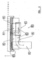
- Figure 2 is a schematic plan view of the apparatus
- Figures 1 and 3 are schematic illustrations of the means by which a single two-layer swath 19 is formed, comprising lower layer 19a derived (wholly or mainly) from the first conditioner unit 15, and upper layer 15b derived from the second conditioner unit 16.
- the first and second conditioner units 15, 16 are arranged side by side with respect to the direction of forward travel 12.
- the conditioner units 15, 16 also to be spaced apart from each other with respect to the direction of forward travel 12 (see Figure 4).
- first conditioner unit 15 is spaced a short distance forwardly of second conditioner unit 16, with respect to the direction of forward travel, but the conditioned crop coming from the first conditioner unit 15 is conveyed laterally by the transfer device 17 so that it can fall under gravity onto the ground behind the second conditioner unit 16, and forming the underlying layer 19a, wholly or at least mainly, of the 2-layered swath.
- the second conditioner unit 16 has swath boards 20 and 21, which direct the conditioned crop which is being discharged rearwardly of the second conditioner unit 16, and so as to form, at least mainly, the upper layer 19b of the 2-layer swath.
- the swath board 20 may happen to cause some of the conditioned crop from the second conditioner unit 16 to tend to escape i.e. to fall downwardly under gravity too soon, such material is engaged by the material being discharged laterally by the transfer device 17, and is carried over so as to form together the underlying layer 19a.
- Figure 4 also shows diagrammatically how the tandem arrangement of conditioner units 15 and 16 can carry out successive working parts of movements, in opposite directions, to give an advantageous gathering of known crop, and joint formation of a single 2-layered swath by the two paths of movement.
- conditioner units 15 and 16 form a unitary assembly which can be towed behind a propelling vehicle.
- the unitary assembly may be front mounted on a propelling vehicle.
- the illustrated embodiment shown in the drawings may be modified such that the swath deposited by the conditioner 16 can be laid on the left hand side of the conditioner unit 16 (by its swath boards), and the material from the conditioner 15 can be laid on the right hand side of conditioner 16 (together with the material falling from the swath boards i.e. they do not form partly one on the other.
Landscapes
- Life Sciences & Earth Sciences (AREA)
- Environmental Sciences (AREA)
- Harvester Elements (AREA)
- Electrical Discharge Machining, Electrochemical Machining, And Combined Machining (AREA)
Abstract
Description
- This invention relates to a mower/conditioner apparatus which comprises a cutter bar, and a tandem arrangement of conditioner units located behind the cutter bar and arranged side by side to extend transversely of the direction of forward travel.
- It is well known to arrange a conditioner unit rearwardly of a transversely extending cutter bar e.g. in a disc mower arrangement, and to feed mown grass (or other standing crop) cut by the cutter bar to the conditioner unit so as to apply a "conditioning" action on the mown crop (the conditioner, and the cutter bar, can also be arranged side by side and offset in the working direction). The "conditioned" crop is then discharged onto the ground rearwardly of the conditioner unit in the form of a "swath".
- The construction and operation of cutter bars and conditioner units will be well known to those of ordinary skill in the art, and therefore do not need to be described in detail herein. The document DE-C-18931684 discloses a mower/conditioner apparatus comprising a front and two side mower/conditioners wherein the side units are provided with a transfer device to transfer the crop to the middle swath.
- However, the present invention is concerned with a mower/conditioner apparatus having a pair of conditioner units which are laterally spaced from each other (with respect to the direction of forward travel), and rearwardly of a forward cutter bar (or more than one cutter bar if preferred i.e. a separate cutter bar associated with each conditioner unit), and seeks to provide an improved means for discharging the conditioned crop from the two conditioner units.
- Thus, in known apparatus having a tandem arrangement of conditioner units, with each conditioner unit being arranged to discharge the conditioned crop in a rearward direction, either two separate swaths are formed or, with suitable guide arrangements (swath boards) a combined single swath can be formed.
- The invention seeks to provide an improved means for guiding the discharge of conditioned crop from the two conditioner units, and in such a way that a single swath is formed and of a width which is considerably smaller e.g. half the width of the cutter bar(s).
- According to the invention there is provided a mower/conditioner apparatus which comprises:
- a transversely extending cutter bar;
- first and second conditioner units located behind the cutter bar which are laterally spaced from each other with respect to the direction of forward travel, and with each conditioner unit being arranged (a) to receive mown crop from the cutter bar, (b) to condition the crop and (c) to discharge the conditioned crop in a rearward direction; and
- a transfer device arranged rearwardly of the first conditioner unit to receive conditioned crop from the first unit and to transfer the conditioned crop in a direction transversely of the direction of travel and towards the second conditioner unit so that, in combination with the stream of conditioned crop being discharged from the second conditioner unit, there is formed a single two-layered swath behind the apparatus, and in which the underlying layer is derived, wholly or mainly, from the crop conditioned by the first conditioner unit.
- The invention therefore enables a single swath to be formed behind the apparatus, of lesser width than the width of the cutter bar, and without need to apply high speed transverse movement to the conditioned crop from the first conditioner unit. This is because the conditioned crop can be discharged to one side of the rear of the second conditioner unit, and underneath the stream of conditioned crop which is being discharged from the second conditioner unit.
- In addition to the advantage of reduced speed required to be imparted to the movement of the conditioned crop from the first conditioner unit (a higher speed would be necessary in the event that it should be required to discharge the conditioned crop from the first conditioner unit above the stream of conditioned crop being discharged from the second conditioner unit), there are two further advantages which may be achieved. Thus, if, as may be preferred, swath boards are attached to the second conditioner unit, and if any conditioned crop may unintentionally fall onto the ground too early i.e. not be directed to a required position on the ground at which the swath is to be formed, such escaping material (possibly 5 to 10% of the total from the second conditioner unit) is engaged by the stream of conditioned crop from the transfer device associated with the first conditioner unit, and is transferred onto the ground where the swath is required, and underneath the stream of the main portion of conditioned crop being discharged from the second conditioner unit.
- Furthermore, because the transfer device is located rearwardly of the first conditioner unit, and in a position so that it can readily receive the material from the first conditioner unit, the overall design of the apparatus, including the transfer device, can be kept relatively compact/short.
- The transfer device can take any suitable form, in order to move the conditioned crop from the first conditioner unit in a transverse direction onto the ground behind the second conditioner unit and underneath the stream of crop being discharged from the second conditioner unit. Examples of device which may be used include an endless conveyor, an auger, and an arrangement of transfer rollers.
- The apparatus of the invention may be provided with a single cutter bar, extending transversely throughout the width of the apparatus, so that one half of the cutter bar is associated with the first conditioner unit, and the other half is associated with the second conditioner unit. Alternatively, separate cutter bar sections may be associated with each conditioner unit.
- The cutter bar(s) may take any suitable form as used in existing designs of grass mowing machines, including disc mowers.
- Preferably, the first and second conditioner units are arranged side by side with respect to the direction of forward travel, so that the conditioned crop from the first conditioner unit is transferred by the transfer device so as to fall onto the ground behind the second conditioner unit and underneath the stream of conditioned crop being discharged from the second conditioner unit.
- However, in an alternative arrangement, the first and second conditioner units are laterally and also longitudinally spaced apart from each other, with respect to the direction of forward travel but arranged in such a way that at least the major portion of the underlying layer of the 2-layered swath is derived from the first conditioner unit.
- Therefore, in one alternative arrangement, the first conditioner unit may be spaced forwardly of the second conditioner unit by a small distance, provided that the transfer device is able to discharge the conditioned crop from the first conditioner unit onto the ground and behind the second conditioner unit so as to form (wholly or at least mainly) the underlying layer of the 2-layered swath formed behind the apparatus.
- However, in a further arrangement, the second conditioner unit may be spaced forwardly of the first conditioner unit (so that the transfer device is able to discharge the conditioned crop from the first conditioner unit onto the ground and behind the second conditioner unit), but in which the first and second conditioner units form a unitary assembly which is (a) towed behind a propelling vehicle or (b) front-mounted on a propelling vehicle.
- Preferred embodiments of the invention will now be described in detail, by way of example only, with reference to the accompanying schematic drawings, in which:
- Figure 1 is a schematic and perspective illustration of a mower/conditioner apparatus according to the invention, having a tandem arrangement of conditioner units arranged side by side, and with improved guiding means to discharge conditioned crop from each of the conditioner units to form a single two-layered swath of conditioned crop behind the apparatus;
- Figure 2 is a schematic plan view of the apparatus;
- Figure 3 is a schematic side view of the apparatus; and
- Figure 4 is a schematic plan view of an alternative embodiment.
- Referring now to the drawings, a preferred embodiment of mower/conditioner apparatus according to the invention is designated generally by
reference 10, and comprises a forward cutter bar 11, extending transversely of the direction offorward travel 12, and in the schematic illustration of Figure 2 taking the form of a series of laterally spaced mower discs 13. Mower discs 13 are well known for use in disc type mowers, and will not be described in detail herein. Also, although Figure 2 shows schematically a single cutter bar 11, the invention includes the possibility of providing separate cutter bar sections, each associated with a respective conditioner unit located behind it - A tandem arrangement of
conditioner units 14 is therefore provided, and which comprises afirst conditioner unit 15 located behind a right hand half of the cutter bar 11, and asecond conditioner unit 16 arranged behind the left hand half of the cutter bar 11. - The
conditioner units forward travel 12. Eachconditioner unit - A
transfer device 17 is arranged rearwardly of thefirst conditioner unit 15 to receive conditioned crop from the first conditioner unit and to transfer the conditioned crop in a direction, shown byarrows 18, which is transversely of the direction offorward travel 12 and towards thesecond conditioner unit 16. Thetransfer device 17 can take any suitable form, including an endless belt, an auger or a series of transfer rollers. It can be seen from Figure 2 that thetransfer device 17 extends substantially throughout the width of thefirst conditioner unit 15, and transfers the conditioned crop in the direction of thearrows 18 so as to fall onto the ground behind thesecond conditioner unit 16 and underneath the stream of conditioned crop which is being discharged from thesecond conditioner unit 16. Some of the material from theconditioner unit 15 can fall onto the ground even beyond theconditioner unit 16; and material may also fall onto the ground partly behind theunit 15 and partly behind theunit 16. - Therefore, a single two-
layered swath 19 can be formed behind theapparatus 10, and which evidently is of lesser width than the width of the cutter bar 11, and furthermore without need to apply high speed transverse movement to the conditioned crop being discharged from the first conditioner unit. This is because the conditioned crop from the first conditioner unit is discharged to one side of the rear of thesecond conditioner unit 16, and underneath the stream of conditioned crop which is being discharged from the second conditioner unit i.e. the underlying layer of the 2-layered swath is derived wholly, or at least mainly from the conditioned crop from thefirst conditioner unit 15. - If, as may be preferred (see Figure 4), swath boards are attached to the
second conditioner unit 16, and in the event that any small proportion of material discharged from the second conditioner unit escapes i.e. falls downwardly too early i.e. not towards the required location of the two layered swath, such material is readily grasped by the material coming from thetransfer device 17 and then directed to fall under gravity onto the ground underneath the main stream of material from thesecond conditioner unit 16. - The
apparatus 10 also has the advantage of providing an overall construction which is compact, by virtue of the arrangement disclosed herein. - Figure 2 is a schematic plan view of the apparatus, and Figures 1 and 3 are schematic illustrations of the means by which a single two-
layer swath 19 is formed, comprisinglower layer 19a derived (wholly or mainly) from thefirst conditioner unit 15, and upper layer 15b derived from thesecond conditioner unit 16. - Preferably, as shown in Figures 1 to 3 of the drawings, the first and
second conditioner units forward travel 12. However, it is within the scope of this invention for theconditioner units - Thus, shown in Figure 4,
first conditioner unit 15 is spaced a short distance forwardly ofsecond conditioner unit 16, with respect to the direction of forward travel, but the conditioned crop coming from thefirst conditioner unit 15 is conveyed laterally by thetransfer device 17 so that it can fall under gravity onto the ground behind thesecond conditioner unit 16, and forming theunderlying layer 19a, wholly or at least mainly, of the 2-layered swath. - Also, shown in Figure 4, the
second conditioner unit 16 hasswath boards second conditioner unit 16, and so as to form, at least mainly, theupper layer 19b of the 2-layer swath. In the event that theswath board 20 may happen to cause some of the conditioned crop from thesecond conditioner unit 16 to tend to escape i.e. to fall downwardly under gravity too soon, such material is engaged by the material being discharged laterally by thetransfer device 17, and is carried over so as to form together theunderlying layer 19a. - Figure 4 also shows diagrammatically how the tandem arrangement of
conditioner units - It is preferred that the
conditioner units - Also, although not shown, the illustrated embodiment shown in the drawings may be modified such that the swath deposited by the
conditioner 16 can be laid on the left hand side of the conditioner unit 16 (by its swath boards), and the material from theconditioner 15 can be laid on the right hand side of conditioner 16 (together with the material falling from the swath boards i.e. they do not form partly one on the other.
Claims (9)
- A mower/conditioner apparatus (10) which comprises:a cutter bar (11) extending transversely of the direction of forward travel (12);a tandem arrangement of conditioner units (14) located behind the cutter bar (11) and comprising first and second conditioner units (15, 16) which are laterally spaced from each other with respect to the direction of forward travel (12), and with each conditioner unit (15, 16) being arranged (a) to receive mown crop from the cutter bar (11), (b) to condition the crop and (c) to discharge the conditioned crop in a rearward direction; anda transfer device (17) arranged rearwardly of the first conditioner unit (15) to receive conditioned crop from the first unit (15) and to transfer the conditioned crop in a direction (18) transversely of the direction of forward travel (12) and towards the second conditioner unit (16) so that, in combination with the stream of conditioned crop being discharged from the second conditioner unit (16) there is formed a single two-layered swath (19a, 19b) behind the apparatus (10), and in which the underlying layer is derived, wholly or mainly, from the crop conditioned by the first conditioner unit (15).
- Apparatus according to claim 1, in which the transfer device comprises an endless belt, an auger, or an arrangement of transfer rollers.
- Apparatus according to claim 1 or 2, in which the cutter bar (11) comprises a single bar extending throughout the width of the apparatus.
- Apparatus according to claim 3, in which the cutter bar (11) comprises an arrangement of cutter discs (13).
- Apparatus according to anyone of the preceding claims, in which the second conditioner unit (16) includes swath-forming guides (20) which guide the rearward discharge of conditioned crop from the second conditioner unit (16).
- Apparatus according to any one of the preceding claims, in which the first and second conditioner units (15, 16) are spaced apart from each other with respect to the direction of forward travel (12).
- Apparatus according to any one of claims 1 to 5, in which the first and second conditioner units (15, 16) are arranged side by side with respect to the direction of forward travel (12) so that conditioned crop from the first conditioner unit (15) is transferred by the transfer device (17) onto the ground behind the second conditioner unit (16) and underneath the stream of conditioned crop being discharged from the second conditioner unit (16).
- Apparatus according to any one of claims 1 to 5, in which the first and second conditioner units 15, 16 form a unitary assembly which is adapted to be (a) towed behind a propelling vehicle or (b) front mounted on a propelling vehicle.
- Apparatus according to claim 8, in which the second conditioner unit 16 is spaced forwardly of the first conditioner unit 15.
Applications Claiming Priority (3)
| Application Number | Priority Date | Filing Date | Title |
|---|---|---|---|
| GB0030787 | 2000-12-18 | ||
| GBGB0030787.6A GB0030787D0 (en) | 2000-12-18 | 2000-12-18 | Mower/conditioner apparatus |
| PCT/GB2001/005451 WO2002049415A1 (en) | 2000-12-18 | 2001-12-10 | Mower/conditioner apparatus |
Publications (2)
| Publication Number | Publication Date |
|---|---|
| EP1343364A1 EP1343364A1 (en) | 2003-09-17 |
| EP1343364B1 true EP1343364B1 (en) | 2006-04-12 |
Family
ID=9905272
Family Applications (1)
| Application Number | Title | Priority Date | Filing Date |
|---|---|---|---|
| EP01271140A Expired - Lifetime EP1343364B1 (en) | 2000-12-18 | 2001-12-10 | Mower/conditioner apparatus |
Country Status (6)
| Country | Link |
|---|---|
| EP (1) | EP1343364B1 (en) |
| AT (1) | ATE322812T1 (en) |
| AU (1) | AU2002222152A1 (en) |
| DE (1) | DE60118779T2 (en) |
| GB (1) | GB0030787D0 (en) |
| WO (1) | WO2002049415A1 (en) |
Family Cites Families (10)
| Publication number | Priority date | Publication date | Assignee | Title |
|---|---|---|---|---|
| US2811003A (en) * | 1952-12-30 | 1957-10-29 | A F Meyer Mfg Co | Hay processing machine |
| DE1782799A1 (en) * | 1963-08-05 | 1973-02-01 | Ernst Weichel | MACHINERY ON AGRICULTURAL MACHINERY, IN PARTICULAR FARMER TRACTORS |
| US4099364A (en) * | 1976-11-04 | 1978-07-11 | Owatonna Manufacturing Company, Inc. | Fluffer shield system for crop harvester |
| DE74451T1 (en) * | 1981-09-09 | 1983-08-04 | John Deere S.A., 45011 Orleans | HARVEST CONDITIONING MACHINE, e.g. MEASURING AND CONDITIONING DEVICE OR RECORDING AND CONDITIONING DEVICE. |
| FR2559344B1 (en) * | 1984-02-10 | 1986-11-28 | Bucher Guyer Ag Masch | FORAGE HARVESTING MACHINE WITH LATERAL TRANSPORT |
| GB8601456D0 (en) * | 1986-01-22 | 1986-02-26 | Kidd Farm Machinery | Mowing machine |
| DE3827332A1 (en) * | 1988-08-11 | 1990-02-22 | Greenland Gmbh & Co Kg | Appliance for the mowing and treatment of stalk crop |
| DE4432663A1 (en) * | 1994-09-14 | 1996-03-21 | Same Spa | Harvester complete with cutter and screw=fed processing |
| NL1008026C2 (en) * | 1998-01-14 | 1999-07-15 | Greenland Nieuw Vennep Bv | Mowing machine for grass and other crops |
| DE19931684C1 (en) * | 1999-07-08 | 2000-09-07 | Krone Bernhard Gmbh Maschf | Agricultural harvester has a combined straw chopping and spreading system with a structured mantle body round the lateral conveyor screw to eject the straw in a swathe with acceleration for spreading over the ground |
-
2000
- 2000-12-18 GB GBGB0030787.6A patent/GB0030787D0/en not_active Ceased
-
2001
- 2001-12-10 AU AU2002222152A patent/AU2002222152A1/en not_active Abandoned
- 2001-12-10 AT AT01271140T patent/ATE322812T1/en not_active IP Right Cessation
- 2001-12-10 WO PCT/GB2001/005451 patent/WO2002049415A1/en not_active Ceased
- 2001-12-10 EP EP01271140A patent/EP1343364B1/en not_active Expired - Lifetime
- 2001-12-10 DE DE60118779T patent/DE60118779T2/en not_active Expired - Lifetime
Also Published As
| Publication number | Publication date |
|---|---|
| EP1343364A1 (en) | 2003-09-17 |
| ATE322812T1 (en) | 2006-04-15 |
| WO2002049415A1 (en) | 2002-06-27 |
| DE60118779D1 (en) | 2006-05-24 |
| AU2002222152A1 (en) | 2002-07-01 |
| GB0030787D0 (en) | 2001-01-31 |
| DE60118779T2 (en) | 2007-03-29 |
Similar Documents
| Publication | Publication Date | Title |
|---|---|---|
| RU2471330C2 (en) | Cutting system with reciprocating knives | |
| US4236369A (en) | Row crop attachment | |
| US6862873B2 (en) | Windrow merging attachment | |
| US3508387A (en) | Harvesting attachment for combine | |
| EP0406766A1 (en) | Mower | |
| US20060123764A1 (en) | Adjustable windrower shields | |
| CA2259049C (en) | Windrow grouper arrangement | |
| US7574851B1 (en) | Flexibly mounted side deflector | |
| CA3002835C (en) | Draper header for attachment to a harvesting machine | |
| GB2144016A (en) | Combine harvester | |
| EP0882386A3 (en) | A combination of mowers for grass crops | |
| JP5139900B2 (en) | Cutting and harvesting structure of a harvesting and harvesting machine | |
| US20080168755A1 (en) | Harvesting Implement, Particularly Front Harvesting Attachment For Agricultural Harvesting Machines For Taking Up Cereal Crops and Conveying It Further | |
| EP1343364A1 (en) | Mower/conditioner apparatus | |
| CN102045999B (en) | Self-detaching Combine Harvester | |
| US7610741B2 (en) | Mower with foldable mowing units | |
| US6568163B1 (en) | Conveyor arrangement positioned within mower suspension links | |
| JP2010011772A (en) | Reaping and conveying structure of head-feeding combine harvester | |
| JP5324844B2 (en) | Mowing and transporting structure for self-detaching combine | |
| EP1310149A1 (en) | Crop conditioner machine | |
| JPS6345863Y2 (en) | ||
| WO1999033332A1 (en) | Mower for cutting standing crop | |
| JP5324843B2 (en) | Mowing and transporting structure for self-detaching combine | |
| JP3137606B2 (en) | Cutting blade drive for mowing equipment | |
| JPS6338741Y2 (en) |
Legal Events
| Date | Code | Title | Description |
|---|---|---|---|
| PUAI | Public reference made under article 153(3) epc to a published international application that has entered the european phase |
Free format text: ORIGINAL CODE: 0009012 |
|
| 17P | Request for examination filed |
Effective date: 20020816 |
|
| AK | Designated contracting states |
Kind code of ref document: A1 Designated state(s): AT BE CH CY DE DK ES FI FR GB GR IE IT LI LU MC NL PT SE TR |
|
| GRAP | Despatch of communication of intention to grant a patent |
Free format text: ORIGINAL CODE: EPIDOSNIGR1 |
|
| GRAS | Grant fee paid |
Free format text: ORIGINAL CODE: EPIDOSNIGR3 |
|
| GRAA | (expected) grant |
Free format text: ORIGINAL CODE: 0009210 |
|
| AK | Designated contracting states |
Kind code of ref document: B1 Designated state(s): AT BE CH CY DE DK ES FI FR GB GR IE IT LI LU MC NL PT SE TR |
|
| PG25 | Lapsed in a contracting state [announced via postgrant information from national office to epo] |
Ref country code: IT Free format text: LAPSE BECAUSE OF FAILURE TO SUBMIT A TRANSLATION OF THE DESCRIPTION OR TO PAY THE FEE WITHIN THE PRE;WARNING: LAPSES OF ITALIAN PATENTS WITH EFFECTIVE DATE BEFORE 2007 MAY HAVE OCCURRED AT ANY TIME BEFORE 2007. THE CORRECT EFFECTIVE DATE MAY BE DIFFERENT FROM THE ONE RECORDED.SCRIBED TIME-LIMIT Effective date: 20060412 Ref country code: LI Free format text: LAPSE BECAUSE OF FAILURE TO SUBMIT A TRANSLATION OF THE DESCRIPTION OR TO PAY THE FEE WITHIN THE PRESCRIBED TIME-LIMIT Effective date: 20060412 Ref country code: BE Free format text: LAPSE BECAUSE OF FAILURE TO SUBMIT A TRANSLATION OF THE DESCRIPTION OR TO PAY THE FEE WITHIN THE PRESCRIBED TIME-LIMIT Effective date: 20060412 Ref country code: FI Free format text: LAPSE BECAUSE OF FAILURE TO SUBMIT A TRANSLATION OF THE DESCRIPTION OR TO PAY THE FEE WITHIN THE PRESCRIBED TIME-LIMIT Effective date: 20060412 Ref country code: AT Free format text: LAPSE BECAUSE OF FAILURE TO SUBMIT A TRANSLATION OF THE DESCRIPTION OR TO PAY THE FEE WITHIN THE PRESCRIBED TIME-LIMIT Effective date: 20060412 Ref country code: CH Free format text: LAPSE BECAUSE OF FAILURE TO SUBMIT A TRANSLATION OF THE DESCRIPTION OR TO PAY THE FEE WITHIN THE PRESCRIBED TIME-LIMIT Effective date: 20060412 Ref country code: NL Free format text: LAPSE BECAUSE OF FAILURE TO SUBMIT A TRANSLATION OF THE DESCRIPTION OR TO PAY THE FEE WITHIN THE PRESCRIBED TIME-LIMIT Effective date: 20060412 |
|
| REG | Reference to a national code |
Ref country code: GB Ref legal event code: FG4D |
|
| REG | Reference to a national code |
Ref country code: CH Ref legal event code: EP |
|
| REF | Corresponds to: |
Ref document number: 60118779 Country of ref document: DE Date of ref document: 20060524 Kind code of ref document: P |
|
| REG | Reference to a national code |
Ref country code: IE Ref legal event code: FG4D |
|
| PG25 | Lapsed in a contracting state [announced via postgrant information from national office to epo] |
Ref country code: DK Free format text: LAPSE BECAUSE OF FAILURE TO SUBMIT A TRANSLATION OF THE DESCRIPTION OR TO PAY THE FEE WITHIN THE PRESCRIBED TIME-LIMIT Effective date: 20060712 |
|
| PG25 | Lapsed in a contracting state [announced via postgrant information from national office to epo] |
Ref country code: ES Free format text: LAPSE BECAUSE OF FAILURE TO SUBMIT A TRANSLATION OF THE DESCRIPTION OR TO PAY THE FEE WITHIN THE PRESCRIBED TIME-LIMIT Effective date: 20060723 |
|
| REG | Reference to a national code |
Ref country code: SE Ref legal event code: TRGR |
|
| PG25 | Lapsed in a contracting state [announced via postgrant information from national office to epo] |
Ref country code: PT Free format text: LAPSE BECAUSE OF FAILURE TO SUBMIT A TRANSLATION OF THE DESCRIPTION OR TO PAY THE FEE WITHIN THE PRESCRIBED TIME-LIMIT Effective date: 20060912 |
|
| NLV1 | Nl: lapsed or annulled due to failure to fulfill the requirements of art. 29p and 29m of the patents act | ||
| REG | Reference to a national code |
Ref country code: CH Ref legal event code: PL |
|
| ET | Fr: translation filed | ||
| PG25 | Lapsed in a contracting state [announced via postgrant information from national office to epo] |
Ref country code: IE Free format text: LAPSE BECAUSE OF NON-PAYMENT OF DUE FEES Effective date: 20061211 |
|
| PG25 | Lapsed in a contracting state [announced via postgrant information from national office to epo] |
Ref country code: MC Free format text: LAPSE BECAUSE OF NON-PAYMENT OF DUE FEES Effective date: 20061231 |
|
| PLBE | No opposition filed within time limit |
Free format text: ORIGINAL CODE: 0009261 |
|
| STAA | Information on the status of an ep patent application or granted ep patent |
Free format text: STATUS: NO OPPOSITION FILED WITHIN TIME LIMIT |
|
| 26N | No opposition filed |
Effective date: 20070115 |
|
| PG25 | Lapsed in a contracting state [announced via postgrant information from national office to epo] |
Ref country code: GR Free format text: LAPSE BECAUSE OF FAILURE TO SUBMIT A TRANSLATION OF THE DESCRIPTION OR TO PAY THE FEE WITHIN THE PRESCRIBED TIME-LIMIT Effective date: 20060713 |
|
| PG25 | Lapsed in a contracting state [announced via postgrant information from national office to epo] |
Ref country code: LU Free format text: LAPSE BECAUSE OF NON-PAYMENT OF DUE FEES Effective date: 20061210 Ref country code: TR Free format text: LAPSE BECAUSE OF FAILURE TO SUBMIT A TRANSLATION OF THE DESCRIPTION OR TO PAY THE FEE WITHIN THE PRESCRIBED TIME-LIMIT Effective date: 20060412 |
|
| PG25 | Lapsed in a contracting state [announced via postgrant information from national office to epo] |
Ref country code: CY Free format text: LAPSE BECAUSE OF FAILURE TO SUBMIT A TRANSLATION OF THE DESCRIPTION OR TO PAY THE FEE WITHIN THE PRESCRIBED TIME-LIMIT Effective date: 20060412 |
|
| REG | Reference to a national code |
Ref country code: FR Ref legal event code: PLFP Year of fee payment: 15 |
|
| REG | Reference to a national code |
Ref country code: FR Ref legal event code: PLFP Year of fee payment: 16 |
|
| REG | Reference to a national code |
Ref country code: FR Ref legal event code: PLFP Year of fee payment: 17 |
|
| PGFP | Annual fee paid to national office [announced via postgrant information from national office to epo] |
Ref country code: SE Payment date: 20201221 Year of fee payment: 20 Ref country code: FR Payment date: 20201223 Year of fee payment: 20 Ref country code: GB Payment date: 20201223 Year of fee payment: 20 Ref country code: DE Payment date: 20201211 Year of fee payment: 20 |
|
| REG | Reference to a national code |
Ref country code: DE Ref legal event code: R071 Ref document number: 60118779 Country of ref document: DE |
|
| REG | Reference to a national code |
Ref country code: GB Ref legal event code: PE20 Expiry date: 20211209 |
|
| REG | Reference to a national code |
Ref country code: SE Ref legal event code: EUG |
|
| PG25 | Lapsed in a contracting state [announced via postgrant information from national office to epo] |
Ref country code: GB Free format text: LAPSE BECAUSE OF EXPIRATION OF PROTECTION Effective date: 20211209 |