EP1342484A1 - Improvements in nasal cannulae - Google Patents
Improvements in nasal cannulae Download PDFInfo
- Publication number
- EP1342484A1 EP1342484A1 EP03251298A EP03251298A EP1342484A1 EP 1342484 A1 EP1342484 A1 EP 1342484A1 EP 03251298 A EP03251298 A EP 03251298A EP 03251298 A EP03251298 A EP 03251298A EP 1342484 A1 EP1342484 A1 EP 1342484A1
- Authority
- EP
- European Patent Office
- Prior art keywords
- nasal
- prong
- gas
- inner tubular
- passage
- Prior art date
- Legal status (The legal status is an assumption and is not a legal conclusion. Google has not performed a legal analysis and makes no representation as to the accuracy of the status listed.)
- Granted
Links
- 230000000712 assembly Effects 0.000 claims description 3
- 238000000429 assembly Methods 0.000 claims description 3
- 239000007789 gas Substances 0.000 description 30
- QVGXLLKOCUKJST-UHFFFAOYSA-N atomic oxygen Chemical compound [O] QVGXLLKOCUKJST-UHFFFAOYSA-N 0.000 description 13
- 239000001301 oxygen Substances 0.000 description 13
- 229910052760 oxygen Inorganic materials 0.000 description 13
- 239000000203 mixture Substances 0.000 description 4
- IJGRMHOSHXDMSA-UHFFFAOYSA-N Atomic nitrogen Chemical compound N#N IJGRMHOSHXDMSA-UHFFFAOYSA-N 0.000 description 2
- -1 for example Substances 0.000 description 2
- 238000011109 contamination Methods 0.000 description 1
- 230000003247 decreasing effect Effects 0.000 description 1
- 238000010790 dilution Methods 0.000 description 1
- 239000012895 dilution Substances 0.000 description 1
- 239000001307 helium Substances 0.000 description 1
- 229910052734 helium Inorganic materials 0.000 description 1
- SWQJXJOGLNCZEY-UHFFFAOYSA-N helium atom Chemical compound [He] SWQJXJOGLNCZEY-UHFFFAOYSA-N 0.000 description 1
- 239000012528 membrane Substances 0.000 description 1
- 230000017074 necrotic cell death Effects 0.000 description 1
- 229910052757 nitrogen Inorganic materials 0.000 description 1
- 239000012858 resilient material Substances 0.000 description 1
- 238000000926 separation method Methods 0.000 description 1
Images
Classifications
-
- A—HUMAN NECESSITIES
- A61—MEDICAL OR VETERINARY SCIENCE; HYGIENE
- A61M—DEVICES FOR INTRODUCING MEDIA INTO, OR ONTO, THE BODY; DEVICES FOR TRANSDUCING BODY MEDIA OR FOR TAKING MEDIA FROM THE BODY; DEVICES FOR PRODUCING OR ENDING SLEEP OR STUPOR
- A61M16/00—Devices for influencing the respiratory system of patients by gas treatment, e.g. ventilators; Tracheal tubes
- A61M16/06—Respiratory or anaesthetic masks
- A61M16/0666—Nasal cannulas or tubing
-
- A—HUMAN NECESSITIES
- A61—MEDICAL OR VETERINARY SCIENCE; HYGIENE
- A61M—DEVICES FOR INTRODUCING MEDIA INTO, OR ONTO, THE BODY; DEVICES FOR TRANSDUCING BODY MEDIA OR FOR TAKING MEDIA FROM THE BODY; DEVICES FOR PRODUCING OR ENDING SLEEP OR STUPOR
- A61M16/00—Devices for influencing the respiratory system of patients by gas treatment, e.g. ventilators; Tracheal tubes
- A61M16/10—Preparation of respiratory gases or vapours
- A61M16/1005—Preparation of respiratory gases or vapours with O2 features or with parameter measurement
- A61M16/101—Preparation of respiratory gases or vapours with O2 features or with parameter measurement using an oxygen concentrator
Definitions
- the present invention relates to nasal cannulae for the delivery of a gas or gas mixture under pressure to the nasal passages of a patient or user.
- gas throughout this specification is intended not only to embrace a single gas, for example, oxygen but also gas mixtures, for example, mixtures of oxygen/ nitrogen or oxygen/helium.
- Conventional nasal cannulae are used for the inhalation of oxygen or breathable gas mixtures containing oxygen. Some are aimed at semi-mobile users who can gain a degree of independence by using the cannulae together with mobile gas dispensers. Other users include those who work in hostile environments and require the delivery of a breathable gas whilst in the hostile environment.
- nasal cannulae particularly for semi-mobile users are clearly advantageous, they can also present problems due to air entrainment with the subsequent dilution of the delivered gas.
- a nasal cannula It is known from WO-A-92/20392 for a nasal cannula to include a tubular insert element having a distal portion to be placed in a nasal passage and a proximal portion for connection to a supply line for oxygen or an oxygen-enriched gas.
- the distal portion is formed of a flexible and resilient material and has a divergent, generally frusto-conical configuration.
- the cannula provides a positive and comfortable fit in the nasal passage and is conveniently used with high humidity, high flowrate oxygen-enriched air supplied by oxygen-concentrators employing gas separation membranes.
- the tubular insert element is conical in shape, air can be entrained through the gap between the nasal passage and the cone thereby decreasing the oxygen concentration of the inhaled gas.
- a nasal cannula for use in administering a gas under pressure through a nasal passage of a user comprises at least one tubular nasal prong assembly including
- the outer sleeve is in the form of a shroud which extends over a portion of the inner tubular prong formed with an array of through holes (i.e. orifices), the arrangement being such that when gas from the supply line passes through the inner tubular prong most will be delivered to the distal end for delivery to the nasal passage but some will exit the array of holes in to the annular passage to form a shielding stream
- the flow of gas through the array of holes is no more than 50% of the flow of gas leaving the distal end of the tubular nasal prong.
- FIG. 1 where there is shown a conventional nasal cannula which includes a supply line 2 for delivering gas under pressure from a source (not shown) to the proximal ends of two tubular nasal prongs 4.
- a supply line 2 for delivering gas under pressure from a source (not shown) to the proximal ends of two tubular nasal prongs 4.
- the distal end of each prong 4 is arranged adjacent a nasal passage of the user and the gas flow emerging from each distal end impinges on the nose and face of the user.
- the tubular nasal prong 4 forms part of a tubular nasal prong assembly which includes an outer sleeve in the form of a shroud 8 which extends over a portion of the inner tubular nasal prong 4 and defines with the inner tubular nasal prong 4 an annular passage 10.
- a tubular nasal prong assembly which includes an outer sleeve in the form of a shroud 8 which extends over a portion of the inner tubular nasal prong 4 and defines with the inner tubular nasal prong 4 an annular passage 10.
- the shroud 8 extends over that portion of the tubular nasal prong 4 in which the array of holes 6 is formed.
- the shroud 8 is of conical form and generally concentric with the inner tubular nasal prong 4.
- a portion of the gas will flow through the inner tubular nasal prong 4 and be split in to two streams, namely a central main jet which extends from the distal end of the prong 4 and a shrouding stream which passes through the holes 6 and extends from the annular passage 10.
- the central main jet and the shrouding stream are generally concentric so that the shrouding stream shields the main jet from the surrounding gas atmosphere.
- the array of holes 6 are sized and numbered so that the central main jet has a relatively high flow rate whilst the shrouding stream has a relatively low flow rate.
- the shrouding stream minimises the amount of atmosphere entrained allowing for a higher concentration of gas supplied reaching the airways of a user and the avoidance of contamination by polluted atmosphere.
- tubular nasal prong assemblies each of which includes an outer sleeve in the form of a shroud 8 which extends over a portion of an inner tubular nasal prong 4 an annular passage 10.
- the shroud 8 is generally concentric with the inner tubular nasal prong 4 and is maintained in place, that is, spaced relative to the nasal prong 4 by supports 12.
- tubular nasal prong 4 and the shroud 8 are dimensioned and configured so that the central main jet has a relatively high flow rate whilst the shrouding stream has a relatively low flow rate.
- the configuration of the nasal cannulae subject of the above described embodiments provides two gas streams, one of high flow through the prong and one of lower flow through the shroud which shields the central main jet from the surrounding atmosphere.
- cannulae have been illustrated and described which provides a tubular nasal prong assembly for each nasal passage of a user, only a single prong assembly may be desired in some applications.
- shrouding stream acts as a reservoir and helps to compensate for varying and random oxygen needs particularly in the case of users not having full mobility.
- nasal cannula described with reference to Figures 2 and 3 is very efficient it has been found that it can be used with oxygen concentrators which normally could not be used with nasal cannulae, for example, concentrators which produce oxygen concentrations of only 40% by volume. Thus cheaper and smaller oxygen concentrators can be used with the nasal cannula of the present invention.
Landscapes
- Health & Medical Sciences (AREA)
- Pulmonology (AREA)
- Hematology (AREA)
- Life Sciences & Earth Sciences (AREA)
- Engineering & Computer Science (AREA)
- Anesthesiology (AREA)
- Biomedical Technology (AREA)
- Heart & Thoracic Surgery (AREA)
- Otolaryngology (AREA)
- Emergency Medicine (AREA)
- Animal Behavior & Ethology (AREA)
- General Health & Medical Sciences (AREA)
- Public Health (AREA)
- Veterinary Medicine (AREA)
- Respiratory Apparatuses And Protective Means (AREA)
- External Artificial Organs (AREA)
- Pharmaceuticals Containing Other Organic And Inorganic Compounds (AREA)
Abstract
Description
- The present invention relates to nasal cannulae for the delivery of a gas or gas mixture under pressure to the nasal passages of a patient or user.
- For the avoidance of doubt the use of the term "gas" throughout this specification is intended not only to embrace a single gas, for example, oxygen but also gas mixtures, for example, mixtures of oxygen/ nitrogen or oxygen/helium.
- Conventional nasal cannulae are used for the inhalation of oxygen or breathable gas mixtures containing oxygen. Some are aimed at semi-mobile users who can gain a degree of independence by using the cannulae together with mobile gas dispensers. Other users include those who work in hostile environments and require the delivery of a breathable gas whilst in the hostile environment.
- Although the use of such nasal cannulae particularly for semi-mobile users are clearly advantageous, they can also present problems due to air entrainment with the subsequent dilution of the delivered gas.
- This problem has been addressed by the use of masks which can regulate the amount of air entrained. The main drawbacks to the use of these known masks are:
- uncomfortable to wear, leading possibly to necrosis
- heavy and bulky
- complicated to use
- unesthetic
- It is an aim of the present invention to provide a nasal cannula which obviates or minimises these drawbacks and , furthermore in the case of the user working in a hostile environment, minimises the possibility of the entrainment of gases forming part of the hostile environment.
- It is known from WO-A-92/20392 for a nasal cannula to include a tubular insert element having a distal portion to be placed in a nasal passage and a proximal portion for connection to a supply line for oxygen or an oxygen-enriched gas. The distal portion is formed of a flexible and resilient material and has a divergent, generally frusto-conical configuration. The cannula provides a positive and comfortable fit in the nasal passage and is conveniently used with high humidity, high flowrate oxygen-enriched air supplied by oxygen-concentrators employing gas separation membranes. Although the tubular insert element is conical in shape, air can be entrained through the gap between the nasal passage and the cone thereby decreasing the oxygen concentration of the inhaled gas.
- According to the present invention a nasal cannula for use in administering a gas under pressure through a nasal passage of a user comprises at least one tubular nasal prong assembly including
- i)
- an inner tubular prong having a distal end to be placed in or adjacent the nasal passage and a proximal end for connection to a supply line for the gas and
- ii)
- an outer sleeve extending over at least a portion of the inner tubular prong to define with the inner tubular prong an annular passage, the annular passage being in communication with the supply line, the arrangement being such that when gas flows through the supply line most will pass through the distal end of the inner tubular prong for delivery to the nasal passage but some will pass through the annular passage to form a shielding stream.
- In one embodiment, the outer sleeve is in the form of a shroud which extends over a portion of the inner tubular prong formed with an array of through holes (i.e. orifices), the arrangement being such that when gas from the supply line passes through the inner tubular prong most will be delivered to the distal end for delivery to the nasal passage but some will exit the array of holes in to the annular passage to form a shielding stream
- Preferably, the flow of gas through the array of holes is no more than 50% of the flow of gas leaving the distal end of the tubular nasal prong.
- In a second embodiment the outer sleeve is in the form of a shroud which extends over a portion of the inner tubular prong and is spaced from the inner tubular prong by at least one support
- An embodiment of the nasal cannula according to the invention will now be described, by way of example, reference being made to the Figures of the accompanying diagrammatic drawings in which:
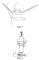
- Figure 1 is a perspective view of a conventional nasal cannula applied to a patient;
- Figure 2 is a schematic view of one tubular nasal prong assembly forming part of a first embodiment of a nasal cannula according to the present invention; and
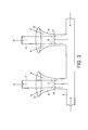
- Figure 3 is a schematic view of two tubular nasal prong assemblies forming part of a second embodiment of a nasal cannula according to the present invention.
- Referring first to Figure 1 where there is shown a conventional nasal cannula which includes a
supply line 2 for delivering gas under pressure from a source (not shown) to the proximal ends of two tubularnasal prongs 4. As shown, the distal end of eachprong 4 is arranged adjacent a nasal passage of the user and the gas flow emerging from each distal end impinges on the nose and face of the user. - Referring now to Figure 2 where like reference numerals denote like parts, according to the present invention the tubular
nasal prong 4 forms part of a tubular nasal prong assembly which includes an outer sleeve in the form of ashroud 8 which extends over a portion of the inner tubularnasal prong 4 and defines with the inner tubularnasal prong 4 anannular passage 10. Approximately midway between the proximal and distal ends of the tubularnasal prong 4 there is formed an array of through holes 6, usually no larger than 2mm diameter. Theshroud 8 extends over that portion of the tubularnasal prong 4 in which the array of holes 6 is formed. Theshroud 8 is of conical form and generally concentric with the inner tubularnasal prong 4. - In use, with gas under pressure flowing through the supply line 2 a portion of the gas will flow through the inner tubular
nasal prong 4 and be split in to two streams, namely a central main jet which extends from the distal end of theprong 4 and a shrouding stream which passes through the holes 6 and extends from theannular passage 10. The central main jet and the shrouding stream are generally concentric so that the shrouding stream shields the main jet from the surrounding gas atmosphere. - The array of holes 6 are sized and numbered so that the central main jet has a relatively high flow rate whilst the shrouding stream has a relatively low flow rate. The shrouding stream minimises the amount of atmosphere entrained allowing for a higher concentration of gas supplied reaching the airways of a user and the avoidance of contamination by polluted atmosphere.
- Referring now to Figure 3 where like reference numerals denote like parts, two tubular nasal prong assemblies are shown each of which includes an outer sleeve in the form of a
shroud 8 which extends over a portion of an inner tubularnasal prong 4 anannular passage 10. Theshroud 8 is generally concentric with the inner tubularnasal prong 4 and is maintained in place, that is, spaced relative to thenasal prong 4 bysupports 12. - In use, with gas under pressure flowing through the supply line 2 a portion of the gas will flow through the inner tubular
nasal prong 4 whilst the remainder will flow through theannular passage 10. The gas flowing through the tubularnasal prong 4 will form a central main jet for delivery to the nasal passage of a user whilst the gas flowing from theannular passage 10 will form a shrouding stream. - As with the previous embodiment, the tubular
nasal prong 4 and theshroud 8 are dimensioned and configured so that the central main jet has a relatively high flow rate whilst the shrouding stream has a relatively low flow rate. - In summary, the configuration of the nasal cannulae subject of the above described embodiments provides two gas streams, one of high flow through the prong and one of lower flow through the shroud which shields the central main jet from the surrounding atmosphere.
- Although cannulae have been illustrated and described which provides a tubular nasal prong assembly for each nasal passage of a user, only a single prong assembly may be desired in some applications.
- Further, the shrouding stream acts as a reservoir and helps to compensate for varying and random oxygen needs particularly in the case of users not having full mobility.
- Since the nasal cannula described with reference to Figures 2 and 3 is very efficient it has been found that it can be used with oxygen concentrators which normally could not be used with nasal cannulae, for example, concentrators which produce oxygen concentrations of only 40% by volume. Thus cheaper and smaller oxygen concentrators can be used with the nasal cannula of the present invention.
Claims (5)
- A nasal cannula for use in administering a gas under pressure through a nasal passage of a user, comprising at least one tubular nasal prong assembly includingi) an inner tubular prong having a distal end to be placed in or adjacent the nasal passage and a proximal end for connection to a supply line for the gas andii) an outer sleeve extending over at least a portion of the inner tubular prong to define with the inner tubular prong an annular passage, the annular passage being in communication with the supply line, the arrangement being such that when gas flows through the supply line most will pass through the distal end of the inner tubular prong for delivery to the nasal passage but some will pass through the annular passage to form a shielding stream.
- A nasal cannula as claimed in Claim 1, in which the outer sleeve is in the form of a shroud which extends over a portion of the inner tubular prong formed with an array of through holes, the arrangement being such that when gas from the supply line passes through the inner tubular prong most will be delivered to the distal end for delivery to the nasal passage but some will pass through the array of holes in to the annular passage and exit the annular passage to form a shielding stream.
- A nasal cannula as claimed in Claim 2, in which the flow of gas through the holes is no more than 50% of the gas flow leaving the distal end of the prong.
- A nasal cannula as claimed in Claim 1, in which the outer sleeve is in the form of a shroud which extends over a portion of the inner tubular prong and is spaced from the inner tubular prong by at least one support.
- A nasal cannula as claimed in any one of Claims 1 to 4, in which two tubular nasal prong assemblies are provided one for each nasal passage of a user.
Applications Claiming Priority (4)
| Application Number | Priority Date | Filing Date | Title |
|---|---|---|---|
| GB0205271 | 2002-03-06 | ||
| GB0205271A GB0205271D0 (en) | 2002-03-06 | 2002-03-06 | Improvements in nasal cannulae |
| GB0211938A GB0211938D0 (en) | 2002-05-23 | 2002-05-23 | Improvements in nasal cannulae |
| GB0211938 | 2002-05-23 |
Publications (2)
| Publication Number | Publication Date |
|---|---|
| EP1342484A1 true EP1342484A1 (en) | 2003-09-10 |
| EP1342484B1 EP1342484B1 (en) | 2007-06-13 |
Family
ID=27758844
Family Applications (1)
| Application Number | Title | Priority Date | Filing Date |
|---|---|---|---|
| EP03251298A Expired - Lifetime EP1342484B1 (en) | 2002-03-06 | 2003-03-04 | Improvements in nasal cannulae |
Country Status (4)
| Country | Link |
|---|---|
| US (1) | US6776163B2 (en) |
| EP (1) | EP1342484B1 (en) |
| AT (1) | ATE364421T1 (en) |
| DE (1) | DE60314309D1 (en) |
Cited By (3)
| Publication number | Priority date | Publication date | Assignee | Title |
|---|---|---|---|---|
| WO2008060523A3 (en) * | 2006-11-15 | 2008-09-12 | Vapotherm Inc | Single nasal prong nasal cannula |
| US10300236B2 (en) | 2012-10-31 | 2019-05-28 | Vapotherm, Inc. | Quiet nasal cannula |
| US11872347B2 (en) | 2013-03-15 | 2024-01-16 | Fisher & Paykel Healthcare Limited | Nasal cannula assemblies and related parts |
Families Citing this family (67)
| Publication number | Priority date | Publication date | Assignee | Title |
|---|---|---|---|---|
| DE10105383C2 (en) * | 2001-02-06 | 2003-06-05 | Heptec Gmbh | Anti-snoring device |
| CN101862496B (en) | 2002-09-06 | 2014-03-12 | 雷斯梅德有限公司 | Cushion for respiratory mask assembly |
| EP2583713B1 (en) | 2002-11-06 | 2020-05-20 | ResMed Pty Ltd | Cushion assembly for a respiratory mask |
| US7588033B2 (en) | 2003-06-18 | 2009-09-15 | Breathe Technologies, Inc. | Methods, systems and devices for improving ventilation in a lung area |
| AU2004266693B2 (en) * | 2003-08-18 | 2011-03-10 | Breathe Technologies, Inc | Method and device for non-invasive ventilation with nasal interface |
| CN103785090B (en) | 2003-12-31 | 2017-09-05 | 瑞思迈有限公司 | Small Oronasal Patient Interface |
| US7007694B2 (en) * | 2004-05-21 | 2006-03-07 | Acoba, Llc | Nasal cannula |
| WO2005118040A1 (en) | 2004-06-03 | 2005-12-15 | Resmed Limited | Cushion for a patient interface |
| US9833354B2 (en) | 2004-12-08 | 2017-12-05 | Theravent, Inc. | Nasal respiratory devices |
| EP1824544B1 (en) | 2004-12-08 | 2013-06-05 | Ventus Medical, Inc. | Respiratory devices and methods of use |
| US10610228B2 (en) | 2004-12-08 | 2020-04-07 | Theravent, Inc. | Passive nasal peep devices |
| NZ721231A (en) | 2005-01-12 | 2018-03-23 | Resmed Ltd | Cushion for patient interface |
| CN101454041B (en) | 2005-09-20 | 2012-12-12 | 呼吸科技公司 | Systems, methods and apparatus for respiratory support of a patient |
| NZ591992A (en) | 2005-10-14 | 2012-11-30 | Resmed Ltd | Breathing mask with cushion attached to frame via lip of cushion engaging within recess between frame outer and inner walls, and guided in via angled protrusion of frame inner wall |
| NZ612787A (en) | 2005-10-25 | 2015-01-30 | Resmed Ltd | Interchangeable mask assembly |
| EP1834660A1 (en) * | 2006-03-17 | 2007-09-19 | Innosuisse Management AG | Device for introducing breathing gas directly in the nose of a user |
| CN101541365A (en) | 2006-05-18 | 2009-09-23 | 呼吸科技公司 | Tracheostoma tracheotomy method and device |
| WO2007146189A2 (en) | 2006-06-07 | 2007-12-21 | Ventus Medical, Inc. | Nasal respiratory devices for positive end-expiratory pressure |
| US7506649B2 (en) * | 2006-06-07 | 2009-03-24 | Ventus Medical, Inc. | Nasal devices |
| EP3053621B1 (en) | 2006-07-28 | 2019-10-16 | ResMed Pty Ltd | Patient interface for delivery of respiratory therapy |
| EP2046430B1 (en) | 2006-07-28 | 2016-04-20 | ResMed Ltd. | Delivery of respiratory therapy |
| EP2068992B1 (en) | 2006-08-03 | 2016-10-05 | Breathe Technologies, Inc. | Devices for minimally invasive respiratory support |
| US8171935B2 (en) * | 2006-11-15 | 2012-05-08 | Vapotherm, Inc. | Nasal cannula with reduced heat loss to reduce rainout |
| JP5911189B2 (en) | 2006-12-15 | 2016-04-27 | レスメド・リミテッドResMed Limited | Respiratory therapy |
| US8517023B2 (en) | 2007-01-30 | 2013-08-27 | Resmed Limited | Mask system with interchangeable headgear connectors |
| NZ578334A (en) | 2007-04-19 | 2011-01-28 | Resmed Ltd | Mask frame connected to face cushion via intervening clip |
| WO2008144589A1 (en) | 2007-05-18 | 2008-11-27 | Breathe Technologies, Inc. | Methods and devices for sensing respiration and providing ventilation therapy |
| NZ771895A (en) | 2007-07-30 | 2022-08-26 | ResMed Pty Ltd | Patient interface |
| JP5519510B2 (en) | 2007-09-26 | 2014-06-11 | ブリーズ・テクノロジーズ・インコーポレーテッド | Ventilation equipment |
| JP5513392B2 (en) | 2007-09-26 | 2014-06-04 | ブリーズ・テクノロジーズ・インコーポレーテッド | Method and apparatus for treating sleep apnea |
| CN108114357B (en) | 2008-03-04 | 2021-05-07 | 瑞思迈私人有限公司 | Mask system |
| US11331447B2 (en) | 2008-03-04 | 2022-05-17 | ResMed Pty Ltd | Mask system with snap-fit shroud |
| WO2009108994A1 (en) | 2008-03-04 | 2009-09-11 | Resmed Ltd | A foam respiratory mask |
| WO2009109004A1 (en) | 2008-03-04 | 2009-09-11 | Resmed Ltd | An interface including a foam cushioning element |
| FR2928284B1 (en) | 2008-03-10 | 2010-06-04 | Safety Production | "CHIP DEFLECTOR CUTTING PLATE" |
| EP2276535B1 (en) | 2008-04-18 | 2020-05-27 | Breathe Technologies, Inc. | Devices for sensing respiration and controlling ventilator functions |
| US8770193B2 (en) | 2008-04-18 | 2014-07-08 | Breathe Technologies, Inc. | Methods and devices for sensing respiration and controlling ventilator functions |
| EP2113274B1 (en) | 2008-04-30 | 2016-04-27 | ResMed R&D Germany GmbH | Apparatus for controlled delivery of a breathing gas to the respiratory tracts of a user |
| JP5844958B2 (en) | 2008-06-04 | 2016-01-20 | レスメド・リミテッドResMedLimited | Patient interface system |
| US8905031B2 (en) | 2008-06-04 | 2014-12-09 | Resmed Limited | Patient interface systems |
| NZ727179A (en) | 2008-06-05 | 2018-06-29 | Resmed Ltd | Treatment of respiratory conditions |
| WO2009151344A1 (en) | 2008-06-12 | 2009-12-17 | Fisher & Paykel Healthcare Limited | Respiratory nasal interface with sealing cap portions |
| WO2010022363A1 (en) | 2008-08-22 | 2010-02-25 | Breathe Technologies, Inc. | Methods and devices for providing mechanical ventilation with an open airway interface |
| CA2941584C (en) | 2008-09-12 | 2019-03-05 | Resmed Ltd | A foam-based interfacing structure method and apparatus |
| WO2010031040A2 (en) * | 2008-09-15 | 2010-03-18 | Ventus Medical, Inc. | Nasal devices, systems and methods |
| JP5711661B2 (en) | 2008-10-01 | 2015-05-07 | ブリーズ・テクノロジーズ・インコーポレーテッド | Ventilator with biofeedback monitoring and controls to improve patient activity and health |
| US9132250B2 (en) | 2009-09-03 | 2015-09-15 | Breathe Technologies, Inc. | Methods, systems and devices for non-invasive ventilation including a non-sealing ventilation interface with an entrainment port and/or pressure feature |
| WO2010115168A1 (en) | 2009-04-02 | 2010-10-07 | Breathe Technologies, Inc. | Methods, systems and devices for non-invasive open ventilation with gas delivery nozzles within an outer tube |
| EP2213324B1 (en) | 2009-01-30 | 2016-07-27 | ResMed R&D Germany GmbH | Patient interface structure and method/tool for manufacturing same |
| US9962512B2 (en) | 2009-04-02 | 2018-05-08 | Breathe Technologies, Inc. | Methods, systems and devices for non-invasive ventilation including a non-sealing ventilation interface with a free space nozzle feature |
| WO2011029074A1 (en) | 2009-09-03 | 2011-03-10 | Breathe Technologies, Inc. | Methods, systems and devices for non-invasive ventilation including a non-sealing ventilation interface with an entrainment port and/or pressure feature |
| US8875711B2 (en) | 2010-05-27 | 2014-11-04 | Theravent, Inc. | Layered nasal respiratory devices |
| WO2012024342A1 (en) | 2010-08-16 | 2012-02-23 | Breathe Technologies, Inc. | Methods, systems and devices using lox to provide ventilatory support |
| CA2811423C (en) | 2010-09-30 | 2019-03-12 | Breathe Technologies, Inc. | Methods, systems and devices for humidifying a respiratory tract |
| TR201707036T4 (en) | 2012-12-04 | 2018-11-21 | Ino Therapeutics Llc | Cannula to minimize dose dilution during administration of nitric oxide |
| US9795756B2 (en) | 2012-12-04 | 2017-10-24 | Mallinckrodt Hospital Products IP Limited | Cannula for minimizing dilution of dosing during nitric oxide delivery |
| WO2014142682A1 (en) | 2013-03-15 | 2014-09-18 | Fisher & Paykel Healthcare Limited | A respiratory assistance device and a method of controlling said device |
| US9925348B2 (en) | 2013-07-17 | 2018-03-27 | Upods, Llc | Gas delivery device |
| US9440039B2 (en) | 2013-07-17 | 2016-09-13 | Upods, Llc | Gas delivery device |
| EP3763409B1 (en) | 2013-08-09 | 2022-02-23 | Fisher & Paykel Healthcare Limited | Asymmetrical nasal delivery elements and fittings for nasal interfaces |
| JP2018501918A (en) * | 2015-01-16 | 2018-01-25 | ユーポッズ エルエルシーUpods, Llc | Gas delivery device |
| USD870269S1 (en) | 2016-09-14 | 2019-12-17 | Fisher & Paykel Healthcare Limited | Nasal cannula assembly |
| USD843561S1 (en) * | 2017-05-29 | 2019-03-19 | Braebon Medical Corporation | Nasal oral cannula |
| US10792449B2 (en) | 2017-10-03 | 2020-10-06 | Breathe Technologies, Inc. | Patient interface with integrated jet pump |
| CN111712195A (en) * | 2017-12-12 | 2020-09-25 | 维亚埃尔医疗股份有限公司 | nose and mouth breathing sensor |
| US11600365B2 (en) | 2017-12-12 | 2023-03-07 | Vyaire Medical, Inc. | Nasal and oral respiration sensor |
| CN111902181A (en) * | 2018-02-13 | 2020-11-06 | 费雪派克医疗保健有限公司 | Collapsible catheter, patient interface and headgear connector |
Citations (4)
| Publication number | Priority date | Publication date | Assignee | Title |
|---|---|---|---|---|
| WO1982001823A1 (en) * | 1980-11-24 | 1982-06-10 | Dow Corning | Nose mask gas delivery device |
| US4660555A (en) * | 1984-09-21 | 1987-04-28 | Payton Hugh W | Oxygen delivery and administration system |
| WO1992020392A1 (en) * | 1991-05-24 | 1992-11-26 | Calor Air Separation Limited | Nasal cannula |
| WO1997021466A1 (en) * | 1995-12-08 | 1997-06-19 | Geo Limited | Breathing apparatus and nozzle therefor |
Family Cites Families (8)
| Publication number | Priority date | Publication date | Assignee | Title |
|---|---|---|---|---|
| US4915105A (en) * | 1988-10-28 | 1990-04-10 | Lee Tien Chu | Miniature respiratory apparatus |
| US6119694A (en) * | 1997-07-24 | 2000-09-19 | Respironics Georgia, Inc. | Nasal mask and headgear |
| US6478026B1 (en) * | 1999-03-13 | 2002-11-12 | Thomas J. Wood | Nasal ventilation interface |
| US6644315B2 (en) * | 1999-06-18 | 2003-11-11 | Saeed Ziaee | Nasal mask |
| US6247470B1 (en) * | 1999-07-07 | 2001-06-19 | Armen G. Ketchedjian | Oxygen delivery, oxygen detection, carbon dioxide monitoring (ODODAC) apparatus and method |
| US6595207B1 (en) * | 2000-09-11 | 2003-07-22 | Southmedic Incorporated | Oxygen diffuser for patient oxygen delivery system |
| US6418928B1 (en) * | 2000-09-25 | 2002-07-16 | Mallinckrodt Inc. | Multi-seal respirator mask |
| US6431172B1 (en) * | 2000-10-20 | 2002-08-13 | Mallinckrodt Inc. | Nasal cannula with inflatable plenum chamber |
-
2003
- 2003-03-04 US US10/378,762 patent/US6776163B2/en not_active Expired - Lifetime
- 2003-03-04 DE DE60314309T patent/DE60314309D1/en not_active Expired - Lifetime
- 2003-03-04 AT AT03251298T patent/ATE364421T1/en not_active IP Right Cessation
- 2003-03-04 EP EP03251298A patent/EP1342484B1/en not_active Expired - Lifetime
Patent Citations (4)
| Publication number | Priority date | Publication date | Assignee | Title |
|---|---|---|---|---|
| WO1982001823A1 (en) * | 1980-11-24 | 1982-06-10 | Dow Corning | Nose mask gas delivery device |
| US4660555A (en) * | 1984-09-21 | 1987-04-28 | Payton Hugh W | Oxygen delivery and administration system |
| WO1992020392A1 (en) * | 1991-05-24 | 1992-11-26 | Calor Air Separation Limited | Nasal cannula |
| WO1997021466A1 (en) * | 1995-12-08 | 1997-06-19 | Geo Limited | Breathing apparatus and nozzle therefor |
Cited By (5)
| Publication number | Priority date | Publication date | Assignee | Title |
|---|---|---|---|---|
| WO2008060523A3 (en) * | 2006-11-15 | 2008-09-12 | Vapotherm Inc | Single nasal prong nasal cannula |
| US10300236B2 (en) | 2012-10-31 | 2019-05-28 | Vapotherm, Inc. | Quiet nasal cannula |
| US11439784B2 (en) | 2012-10-31 | 2022-09-13 | Vapotherm, Inc. | Quiet nasal cannula |
| US12564694B2 (en) | 2012-10-31 | 2026-03-03 | Vapotherm, Inc. | Quiet nasal cannula |
| US11872347B2 (en) | 2013-03-15 | 2024-01-16 | Fisher & Paykel Healthcare Limited | Nasal cannula assemblies and related parts |
Also Published As
| Publication number | Publication date |
|---|---|
| US6776163B2 (en) | 2004-08-17 |
| EP1342484B1 (en) | 2007-06-13 |
| US20030168067A1 (en) | 2003-09-11 |
| DE60314309D1 (en) | 2007-07-26 |
| ATE364421T1 (en) | 2007-07-15 |
Similar Documents
| Publication | Publication Date | Title |
|---|---|---|
| EP1342484B1 (en) | Improvements in nasal cannulae | |
| EP1341572B1 (en) | Oxygen diffuser for patient oxygen delivery system | |
| EP0957960B1 (en) | Breathing circuit apparatus for a nebulizer | |
| US6631719B2 (en) | Lightweight patient oxygen delivery system | |
| AU2011312229B2 (en) | Non-invasive breathing assistance device with flow director | |
| US8893720B2 (en) | Inhalation apparatus | |
| US20200360641A1 (en) | Modular pulmonary treatment system | |
| AU2001256034A1 (en) | Oxygen diffuser for patient oxygen delivery system | |
| WO2001080925A3 (en) | Method and apparatus for pharyngeal augmentation of ventilation | |
| WO1992020392A1 (en) | Nasal cannula | |
| US10322252B2 (en) | Ergonomic nasal cannula | |
| NO20021231D0 (en) | Combination nozzle for inhalation therapy devices for use in oxygen dependent patients | |
| WO2002002052A3 (en) | Aerosol inhalation interface | |
| US11793958B2 (en) | Needle based precision venturi flow-generator for positive pressure ventilation | |
| EP2650034A1 (en) | Entrainment cover and intake module having the same | |
| HK1087360A1 (en) | Patient oxygen delivery mask | |
| HK1087360B (en) | Patient oxygen delivery mask |
Legal Events
| Date | Code | Title | Description |
|---|---|---|---|
| PUAI | Public reference made under article 153(3) epc to a published international application that has entered the european phase |
Free format text: ORIGINAL CODE: 0009012 |
|
| AK | Designated contracting states |
Kind code of ref document: A1 Designated state(s): AT BE BG CH CY CZ DE DK EE ES FI FR GB GR HU IE IT LI LU MC NL PT RO SE SI SK TR |
|
| AX | Request for extension of the european patent |
Extension state: AL LT LV MK |
|
| 17P | Request for examination filed |
Effective date: 20040227 |
|
| AKX | Designation fees paid |
Designated state(s): AT BE BG CH CY CZ DE DK EE ES FI FR GB GR HU IE IT LI LU MC NL PT RO SE SI SK TR |
|
| GRAP | Despatch of communication of intention to grant a patent |
Free format text: ORIGINAL CODE: EPIDOSNIGR1 |
|
| GRAS | Grant fee paid |
Free format text: ORIGINAL CODE: EPIDOSNIGR3 |
|
| GRAA | (expected) grant |
Free format text: ORIGINAL CODE: 0009210 |
|
| AK | Designated contracting states |
Kind code of ref document: B1 Designated state(s): AT BE BG CH CY CZ DE DK EE ES FI FR GB GR HU IE IT LI LU MC NL PT RO SE SI SK TR |
|
| PG25 | Lapsed in a contracting state [announced via postgrant information from national office to epo] |
Ref country code: CH Free format text: LAPSE BECAUSE OF FAILURE TO SUBMIT A TRANSLATION OF THE DESCRIPTION OR TO PAY THE FEE WITHIN THE PRESCRIBED TIME-LIMIT Effective date: 20070613 Ref country code: LI Free format text: LAPSE BECAUSE OF FAILURE TO SUBMIT A TRANSLATION OF THE DESCRIPTION OR TO PAY THE FEE WITHIN THE PRESCRIBED TIME-LIMIT Effective date: 20070613 |
|
| REG | Reference to a national code |
Ref country code: GB Ref legal event code: FG4D |
|
| REG | Reference to a national code |
Ref country code: CH Ref legal event code: EP |
|
| REG | Reference to a national code |
Ref country code: IE Ref legal event code: FG4D |
|
| REF | Corresponds to: |
Ref document number: 60314309 Country of ref document: DE Date of ref document: 20070726 Kind code of ref document: P |
|
| PG25 | Lapsed in a contracting state [announced via postgrant information from national office to epo] |
Ref country code: SE Free format text: LAPSE BECAUSE OF FAILURE TO SUBMIT A TRANSLATION OF THE DESCRIPTION OR TO PAY THE FEE WITHIN THE PRESCRIBED TIME-LIMIT Effective date: 20070913 |
|
| PG25 | Lapsed in a contracting state [announced via postgrant information from national office to epo] |
Ref country code: AT Free format text: LAPSE BECAUSE OF FAILURE TO SUBMIT A TRANSLATION OF THE DESCRIPTION OR TO PAY THE FEE WITHIN THE PRESCRIBED TIME-LIMIT Effective date: 20070613 |
|
| NLV1 | Nl: lapsed or annulled due to failure to fulfill the requirements of art. 29p and 29m of the patents act | ||
| REG | Reference to a national code |
Ref country code: CH Ref legal event code: PL |
|
| PG25 | Lapsed in a contracting state [announced via postgrant information from national office to epo] |
Ref country code: BE Free format text: LAPSE BECAUSE OF FAILURE TO SUBMIT A TRANSLATION OF THE DESCRIPTION OR TO PAY THE FEE WITHIN THE PRESCRIBED TIME-LIMIT Effective date: 20070613 |
|
| PG25 | Lapsed in a contracting state [announced via postgrant information from national office to epo] |
Ref country code: BG Free format text: LAPSE BECAUSE OF FAILURE TO SUBMIT A TRANSLATION OF THE DESCRIPTION OR TO PAY THE FEE WITHIN THE PRESCRIBED TIME-LIMIT Effective date: 20070913 Ref country code: PT Free format text: LAPSE BECAUSE OF FAILURE TO SUBMIT A TRANSLATION OF THE DESCRIPTION OR TO PAY THE FEE WITHIN THE PRESCRIBED TIME-LIMIT Effective date: 20071113 Ref country code: NL Free format text: LAPSE BECAUSE OF FAILURE TO SUBMIT A TRANSLATION OF THE DESCRIPTION OR TO PAY THE FEE WITHIN THE PRESCRIBED TIME-LIMIT Effective date: 20070613 Ref country code: CZ Free format text: LAPSE BECAUSE OF FAILURE TO SUBMIT A TRANSLATION OF THE DESCRIPTION OR TO PAY THE FEE WITHIN THE PRESCRIBED TIME-LIMIT Effective date: 20070613 Ref country code: SI Free format text: LAPSE BECAUSE OF FAILURE TO SUBMIT A TRANSLATION OF THE DESCRIPTION OR TO PAY THE FEE WITHIN THE PRESCRIBED TIME-LIMIT Effective date: 20070613 Ref country code: ES Free format text: LAPSE BECAUSE OF FAILURE TO SUBMIT A TRANSLATION OF THE DESCRIPTION OR TO PAY THE FEE WITHIN THE PRESCRIBED TIME-LIMIT Effective date: 20070924 |
|
| EN | Fr: translation not filed | ||
| PG25 | Lapsed in a contracting state [announced via postgrant information from national office to epo] |
Ref country code: SK Free format text: LAPSE BECAUSE OF FAILURE TO SUBMIT A TRANSLATION OF THE DESCRIPTION OR TO PAY THE FEE WITHIN THE PRESCRIBED TIME-LIMIT Effective date: 20070613 |
|
| PLBE | No opposition filed within time limit |
Free format text: ORIGINAL CODE: 0009261 |
|
| STAA | Information on the status of an ep patent application or granted ep patent |
Free format text: STATUS: NO OPPOSITION FILED WITHIN TIME LIMIT |
|
| PG25 | Lapsed in a contracting state [announced via postgrant information from national office to epo] |
Ref country code: DE Free format text: LAPSE BECAUSE OF FAILURE TO SUBMIT A TRANSLATION OF THE DESCRIPTION OR TO PAY THE FEE WITHIN THE PRESCRIBED TIME-LIMIT Effective date: 20070914 Ref country code: DK Free format text: LAPSE BECAUSE OF FAILURE TO SUBMIT A TRANSLATION OF THE DESCRIPTION OR TO PAY THE FEE WITHIN THE PRESCRIBED TIME-LIMIT Effective date: 20070613 Ref country code: IT Free format text: LAPSE BECAUSE OF FAILURE TO SUBMIT A TRANSLATION OF THE DESCRIPTION OR TO PAY THE FEE WITHIN THE PRESCRIBED TIME-LIMIT Effective date: 20070613 Ref country code: GR Free format text: LAPSE BECAUSE OF FAILURE TO SUBMIT A TRANSLATION OF THE DESCRIPTION OR TO PAY THE FEE WITHIN THE PRESCRIBED TIME-LIMIT Effective date: 20070914 |
|
| 26N | No opposition filed |
Effective date: 20080314 |
|
| PG25 | Lapsed in a contracting state [announced via postgrant information from national office to epo] |
Ref country code: RO Free format text: LAPSE BECAUSE OF FAILURE TO SUBMIT A TRANSLATION OF THE DESCRIPTION OR TO PAY THE FEE WITHIN THE PRESCRIBED TIME-LIMIT Effective date: 20070613 |
|
| PG25 | Lapsed in a contracting state [announced via postgrant information from national office to epo] |
Ref country code: FR Free format text: LAPSE BECAUSE OF FAILURE TO SUBMIT A TRANSLATION OF THE DESCRIPTION OR TO PAY THE FEE WITHIN THE PRESCRIBED TIME-LIMIT Effective date: 20080208 |
|
| PG25 | Lapsed in a contracting state [announced via postgrant information from national office to epo] |
Ref country code: MC Free format text: LAPSE BECAUSE OF NON-PAYMENT OF DUE FEES Effective date: 20080331 |
|
| PG25 | Lapsed in a contracting state [announced via postgrant information from national office to epo] |
Ref country code: EE Free format text: LAPSE BECAUSE OF FAILURE TO SUBMIT A TRANSLATION OF THE DESCRIPTION OR TO PAY THE FEE WITHIN THE PRESCRIBED TIME-LIMIT Effective date: 20070613 Ref country code: IE Free format text: LAPSE BECAUSE OF NON-PAYMENT OF DUE FEES Effective date: 20080304 |
|
| PG25 | Lapsed in a contracting state [announced via postgrant information from national office to epo] |
Ref country code: FI Free format text: LAPSE BECAUSE OF FAILURE TO SUBMIT A TRANSLATION OF THE DESCRIPTION OR TO PAY THE FEE WITHIN THE PRESCRIBED TIME-LIMIT Effective date: 20070613 |
|
| PG25 | Lapsed in a contracting state [announced via postgrant information from national office to epo] |
Ref country code: CY Free format text: LAPSE BECAUSE OF FAILURE TO SUBMIT A TRANSLATION OF THE DESCRIPTION OR TO PAY THE FEE WITHIN THE PRESCRIBED TIME-LIMIT Effective date: 20070613 |
|
| PG25 | Lapsed in a contracting state [announced via postgrant information from national office to epo] |
Ref country code: LU Free format text: LAPSE BECAUSE OF NON-PAYMENT OF DUE FEES Effective date: 20080304 Ref country code: HU Free format text: LAPSE BECAUSE OF FAILURE TO SUBMIT A TRANSLATION OF THE DESCRIPTION OR TO PAY THE FEE WITHIN THE PRESCRIBED TIME-LIMIT Effective date: 20071214 |
|
| PG25 | Lapsed in a contracting state [announced via postgrant information from national office to epo] |
Ref country code: TR Free format text: LAPSE BECAUSE OF FAILURE TO SUBMIT A TRANSLATION OF THE DESCRIPTION OR TO PAY THE FEE WITHIN THE PRESCRIBED TIME-LIMIT Effective date: 20070613 |
|
| PGFP | Annual fee paid to national office [announced via postgrant information from national office to epo] |
Ref country code: GB Payment date: 20180228 Year of fee payment: 16 |
|
| GBPC | Gb: european patent ceased through non-payment of renewal fee |
Effective date: 20190304 |
|
| PG25 | Lapsed in a contracting state [announced via postgrant information from national office to epo] |
Ref country code: GB Free format text: LAPSE BECAUSE OF NON-PAYMENT OF DUE FEES Effective date: 20190304 |