EP1341397A2 - Split shell for hearing aids - Google Patents
Split shell for hearing aids Download PDFInfo
- Publication number
- EP1341397A2 EP1341397A2 EP03075631A EP03075631A EP1341397A2 EP 1341397 A2 EP1341397 A2 EP 1341397A2 EP 03075631 A EP03075631 A EP 03075631A EP 03075631 A EP03075631 A EP 03075631A EP 1341397 A2 EP1341397 A2 EP 1341397A2
- Authority
- EP
- European Patent Office
- Prior art keywords
- housing
- sections
- hearing aid
- receiver
- user
- Prior art date
- Legal status (The legal status is an assumption and is not a legal conclusion. Google has not performed a legal analysis and makes no representation as to the accuracy of the status listed.)
- Granted
Links
Images


Classifications
-
- H—ELECTRICITY
- H04—ELECTRIC COMMUNICATION TECHNIQUE
- H04R—LOUDSPEAKERS, MICROPHONES, GRAMOPHONE PICK-UPS OR LIKE ACOUSTIC ELECTROMECHANICAL TRANSDUCERS; DEAF-AID SETS; PUBLIC ADDRESS SYSTEMS
- H04R25/00—Deaf-aid sets, i.e. electro-acoustic or electro-mechanical hearing aids; Electric tinnitus maskers providing an auditory perception
- H04R25/65—Housing parts, e.g. shells, tips or moulds, or their manufacture
- H04R25/652—Ear tips; Ear moulds
-
- H—ELECTRICITY
- H04—ELECTRIC COMMUNICATION TECHNIQUE
- H04R—LOUDSPEAKERS, MICROPHONES, GRAMOPHONE PICK-UPS OR LIKE ACOUSTIC ELECTROMECHANICAL TRANSDUCERS; DEAF-AID SETS; PUBLIC ADDRESS SYSTEMS
- H04R25/00—Deaf-aid sets, i.e. electro-acoustic or electro-mechanical hearing aids; Electric tinnitus maskers providing an auditory perception
- H04R25/60—Mounting or interconnection of hearing aid parts, e.g. inside tips, housings or to ossicles
- H04R25/609—Mounting or interconnection of hearing aid parts, e.g. inside tips, housings or to ossicles of circuitry
-
- B—PERFORMING OPERATIONS; TRANSPORTING
- B33—ADDITIVE MANUFACTURING TECHNOLOGY
- B33Y—ADDITIVE MANUFACTURING, i.e. MANUFACTURING OF THREE-DIMENSIONAL [3-D] OBJECTS BY ADDITIVE DEPOSITION, ADDITIVE AGGLOMERATION OR ADDITIVE LAYERING, e.g. BY 3-D PRINTING, STEREOLITHOGRAPHY OR SELECTIVE LASER SINTERING
- B33Y80/00—Products made by additive manufacturing
-
- H—ELECTRICITY
- H04—ELECTRIC COMMUNICATION TECHNIQUE
- H04R—LOUDSPEAKERS, MICROPHONES, GRAMOPHONE PICK-UPS OR LIKE ACOUSTIC ELECTROMECHANICAL TRANSDUCERS; DEAF-AID SETS; PUBLIC ADDRESS SYSTEMS
- H04R2225/00—Details of deaf aids covered by H04R25/00, not provided for in any of its subgroups
- H04R2225/023—Completely in the canal [CIC] hearing aids
-
- H—ELECTRICITY
- H04—ELECTRIC COMMUNICATION TECHNIQUE
- H04R—LOUDSPEAKERS, MICROPHONES, GRAMOPHONE PICK-UPS OR LIKE ACOUSTIC ELECTROMECHANICAL TRANSDUCERS; DEAF-AID SETS; PUBLIC ADDRESS SYSTEMS
- H04R2225/00—Details of deaf aids covered by H04R25/00, not provided for in any of its subgroups
- H04R2225/025—In the ear hearing aids [ITE] hearing aids
-
- H—ELECTRICITY
- H04—ELECTRIC COMMUNICATION TECHNIQUE
- H04R—LOUDSPEAKERS, MICROPHONES, GRAMOPHONE PICK-UPS OR LIKE ACOUSTIC ELECTROMECHANICAL TRANSDUCERS; DEAF-AID SETS; PUBLIC ADDRESS SYSTEMS
- H04R2225/00—Details of deaf aids covered by H04R25/00, not provided for in any of its subgroups
- H04R2225/57—Aspects of electrical interconnection between hearing aid parts
-
- H—ELECTRICITY
- H04—ELECTRIC COMMUNICATION TECHNIQUE
- H04R—LOUDSPEAKERS, MICROPHONES, GRAMOPHONE PICK-UPS OR LIKE ACOUSTIC ELECTROMECHANICAL TRANSDUCERS; DEAF-AID SETS; PUBLIC ADDRESS SYSTEMS
- H04R2460/00—Details of hearing devices, i.e. of ear- or headphones covered by H04R1/10 or H04R5/033 but not provided for in any of their subgroups, or of hearing aids covered by H04R25/00 but not provided for in any of its subgroups
- H04R2460/11—Aspects relating to vents, e.g. shape, orientation, acoustic properties in ear tips of hearing devices to prevent occlusion
-
- H—ELECTRICITY
- H04—ELECTRIC COMMUNICATION TECHNIQUE
- H04R—LOUDSPEAKERS, MICROPHONES, GRAMOPHONE PICK-UPS OR LIKE ACOUSTIC ELECTROMECHANICAL TRANSDUCERS; DEAF-AID SETS; PUBLIC ADDRESS SYSTEMS
- H04R25/00—Deaf-aid sets, i.e. electro-acoustic or electro-mechanical hearing aids; Electric tinnitus maskers providing an auditory perception
- H04R25/45—Prevention of acoustic reaction, i.e. acoustic oscillatory feedback
- H04R25/456—Prevention of acoustic reaction, i.e. acoustic oscillatory feedback mechanically
-
- H—ELECTRICITY
- H04—ELECTRIC COMMUNICATION TECHNIQUE
- H04R—LOUDSPEAKERS, MICROPHONES, GRAMOPHONE PICK-UPS OR LIKE ACOUSTIC ELECTROMECHANICAL TRANSDUCERS; DEAF-AID SETS; PUBLIC ADDRESS SYSTEMS
- H04R25/00—Deaf-aid sets, i.e. electro-acoustic or electro-mechanical hearing aids; Electric tinnitus maskers providing an auditory perception
- H04R25/60—Mounting or interconnection of hearing aid parts, e.g. inside tips, housings or to ossicles
- H04R25/604—Mounting or interconnection of hearing aid parts, e.g. inside tips, housings or to ossicles of acoustic or vibrational transducers
-
- H—ELECTRICITY
- H04—ELECTRIC COMMUNICATION TECHNIQUE
- H04R—LOUDSPEAKERS, MICROPHONES, GRAMOPHONE PICK-UPS OR LIKE ACOUSTIC ELECTROMECHANICAL TRANSDUCERS; DEAF-AID SETS; PUBLIC ADDRESS SYSTEMS
- H04R25/00—Deaf-aid sets, i.e. electro-acoustic or electro-mechanical hearing aids; Electric tinnitus maskers providing an auditory perception
- H04R25/65—Housing parts, e.g. shells, tips or moulds, or their manufacture
- H04R25/658—Manufacture of housing parts
Landscapes
- Engineering & Computer Science (AREA)
- Health & Medical Sciences (AREA)
- General Health & Medical Sciences (AREA)
- Neurosurgery (AREA)
- Otolaryngology (AREA)
- Physics & Mathematics (AREA)
- Acoustics & Sound (AREA)
- Signal Processing (AREA)
- Manufacturing & Machinery (AREA)
- Headphones And Earphones (AREA)
Abstract
Description
- The invention pertains to hearing aids that are intended to extend at least in part into the user's ear canal. More particularly, the invention pertains to such hearing aids formed of two locked together housing sections in the absence of a face plate.
- For a number of years it has been common to manufacture in-the-ear, or in-the-canal hearing aids with a hollow body section, custom designed with an exterior periphery intended to match the curvature of the user's ear canal. The hollow body section usually is bounded on all sides but one. Components such as a receiver are inserted through the open side. The receiver has an audio output port which is usually oriented toward the end of the housing intended to have an audio output port.
- The open side is closed with a face plate which usually carries some or all of the remaining necessary components such as a microphone, audio processing circuitry and a power supply such as a battery. The output of the audio processing circuitry is coupled during manufacture to an input port of the receiver.
- The face plate is attached to the body section along a laterally directed seam using a variety of mechanical and/or adhesive solutions. Mechanical solutions have included clamps of various types which enable the face plate to grip the open end of the body section. Adhesives have also been used to strengthen the joint.
- The above constructions produce a seam that is laterally oriented relative to an axis which extends between the ends. This seam must be mechanically strong enough to resist extraction forces applied to the face plate after the aid has been inserted into the user's ear canal.
- The above construction presents manufacturing difficulties. The body section is usually small and is bounded on all sides but the one where the face plate is ultimately attached. Hence, assembling components, such as the receiver or audio processing circuitry into the housing section can be difficult, requiring skill and experience. This results in manufacturing expense and can present reliability problems. In addition, the housing sections are unique as they represent the shape of parts of the user's ear canal, no two of which are the same. This further complicates the assembly process as components are constantly being installed in variably shaped volumes.
- There is thus a continuing need for improved hearing aids of a type that extend, at least in part, into the user's ear canal. Preferably manufacturing costs could be reduced while increasing reliability of operation of the completed unit. It would also be preferable if a larger, more open assembly work area could be provided than has heretofore been available. Finally, it would be preferable if an improved joint could be provided between the various parts of the subject hearing aid.
- For a better understanding of the present invention reference will now be made, by way of example, to the accompanying drawings, in which:
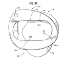
- Fig. 1 is a side elevational view of a longitudinally split hearing aid housing in accordance with the present invention,
- Fig. 2A is a top plan view of the housing sections of Fig. 1 illustrating aspects of the relationship therebetween as those sections are connected together,
- Fig. 2B is a side elevational view of the housing sections of Fig. 2A,
- Fig. 3A is an isometric view of the housing sections of Fig. 1 after assembly,
- Fig. 3B is a top plan view of the assembled housing sections of Fig. 3A,
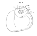
- Fig. 3C is a bottom view of the assembled sections of Fig. 3A,
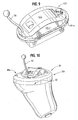
- Fig. 4 is a side elevational view of the housing sections of Fig. 1 with various components installed therein,
- Fig. 5 is a side elevational view of the housing sections of Fig. 4 as those sections are being joined together,
- Fig. 6A is a perspective view of a hearing aid incorporating the housing sections of Fig. 4 after assembly,
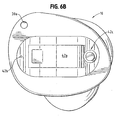
- Fig. 6B is a top plan view of the assembled hearing aid of Fig. 6A,
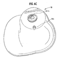
- Fig. 6C is a bottom view of the assembled hearing aid of Fig. 6A,
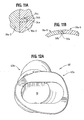
- Fig. 7 is a perspective view of a housing section illustrating an alternate form of receiver mount,
- Fig. 8 is a view of yet another housing section illustrating another alternate view of a receiver mount,
- Fig. 9 is a perspective view of an electronic module for a hearing aid with an extraction member attached thereto,
- Fig. 10 is a perspective view of the hearing aid of Fig. 9B enclosed with an elastomeric sheet,
- Figs. 11A-11B illustrate alternate mechanical latches usable with the hearing aid housing of Fig. 1,
- Fig. 12A is a top plan view of an alternate, laterally split housing configuration,
- Fig. 12B is a side elevational view of the housing configuration of Fig. 12A, and
- Fig. 12C is another side view of the laterally split housing configuration of Fig. 12A.
-
- While embodiments of this invention can take many different forms, specific embodiments thereof are shown in the drawings and will be described herein in detail with the understanding that the present disclosure is to be considered as an exemplification of the principles of the invention and is not intended to limit the invention to the specific embodiment illustrated.
- A hearing aid housing includes first and second sections which when assembled together, form a substantially closed hollow housing. The housing has first and second displaced ends. The housing is most useful in those hearing aids that extend, at least in part, into a user's ear canal. These include in-the-ear, in-the-canal, and completely-in-the-canal hearing aids. In such aids, the portion of the housing that extends into the ear canal is usually, but need not be, shaped to closely conform to the shape of the user's ear canal.
- One end of the housing is intended to be inserted into the user's ear canal, directed toward the ear drum. This end usually has an audio output port. The other end extends toward the user's outer ear and may include a battery door, an audio input port coupled to a microphone and various adjustments.
- The two housing sections interface along a seam which defines a curve that extends axially between the two ends. This housing has no face plate. Each section contributes to forming each of the ends. Alternately, the seam can extend transversely between the ends.
- Each section is formed with a concave central region bounded by spaced apart end regions. When the sections are coupled together, the concave central regions form an internal component receiving volume. The respective mating end regions substantially close the internal volume.
- The seam formed between the two sections is generally transverse to the seam formed between the prior art face plates and respective housings. As a result, when the present hearing aid is extracted from a user's ear canal the extraction forces are generally parallel to the seam and not transverse thereto as is the case with prior art face plates. Therefore, different and simpler mechanical strategies can be used to lock the two sections together as that seam is protected from and better able to withstand the extraction forces. This structure also makes it possible to eliminate any need to use adhesives to join the housing sections together.
- Another advantage of the present hearing aid is that the split housing configuration facilitates assembly. The interiors of both housing sections are exposed and the curvatures are shallower than is the case of prior art housings closed with face plates. Hence, there are no deep interior volumes into which components must be installed. In addition, mounting features having standardized component receiving surfaces can be formed on the interior, concave shapes. The various components such as microphone, speech processing circuits, battery support and receiver can be installed on the standardized surfaces before the housing sections are coupled together. The interconnected components can also be tested prior to coupling the housing sections together.
- In one disclosed embodiment, only two discrete components need be installed in the respective section. One component is the receiver, the other is a module which includes an audio input port, a microphone, speech processing circuitry, and a battery compartment. The output from the speech processing circuitry is coupled to the receiver via conducting wires.
- The module can carry manually manipulatable adjustment elements. The module can also carry a battery access door.
- Fig. 1 illustrates an embodiment of a shell or
housing 10 of an in-the-ear or in-the-canal hearing aid in accordance with the invention. The shell orhousing 10 as illustrated in Fig. 1 is formed of twosections - The
exterior periphery 10' of theshell 10 replicates the shape of a portion of a user's ear canal and a portion of the outer ear.Shell 10 can be formed in either twoseparate sections exterior periphery 10' which is then split into the twosections - It will be understood that the exact methodology of forming the over-all shape of the
housing 10 and/or forming the twosections shell 10 which have an external periphery and an aspect ratio which accurately duplicate portions of the ear canal and the outer ear of the respective user. - When assembled,
sections surfaces 14a-1, -2 and 14b-1, -2. As described below the moulded housing sections bound two substantially closed, component receiving regions. - The
sections housing 10 and define first and second ends 18a-1, -2 and 18b-1, -2. The first, or proximal, ends 18a-1, 18b-1 each join together to partially enclose the proximal or outer ear portion of thehousing 10. Similarly, second, or distal, ends 18a-2, 18b-2 join together to partially close the distal or canal end of thehousing 10. -
Sections surfaces sections -
Sections wall sections sections interior region 20a-1, 20b-1 from adistal region 20a-2, 20b-2. Thewalls 24a, b reduce feedback between a receiver located in the distal region formed ofsections 20a-2, 20b-2, best seen in Fig. 4, from other electrical components located in the proximal region formed ofsections 20a-1, 20b-1. Aslot 24b-1 provides a path between the two component receiving regions for electrical wiring. - Advantages of the
housing 10 include the fact that the respective components can be installed adjacent respective ends 18a-1 and 18a-2 notwithstanding the presence ofwall member 24a. Subsequently, when thesections sections 24a, b completely separates the two groups of components from one another. - The
housing sections grooves slots 28a, b are illustrated, other component receiving and supporting shapes or features could be used without departing from the spirit and scope of the invention.Surfaces 28c, d bound an open proximal end region from which an electronic module extends, in part as discussed below. Receiver component supports can be integrally formed in one or both ofregions 20a-2, 20b-2, depending on the over-all shape, form factor and mounting requirements of the respective receiver, best seen in Figs. 4 and 8. - A
vent 30 can be integrally formed in one of the sections, such assection 10a. Thevent 30 extends fromproximal end 18a-1,port 30a, see Fig. 2A, through the boundedinterior region 20a-1, b-1 through thewall 24a to thedistal end 18a-2,port 30b, best seen in Fig. 3C. The integrally formed vent thus extends between the ends ofsection 10a and is particularly desirable from a manufacturing standpoint since no separate tubing need be inserted into the shell orhousing 10 during the manufacturing process. - The distal ends 18a-2, b-2 also define an audio output port having surfaces, 32a, 32b from which audio emanates into the user's ear canal.
- Figs. 2A and 2B, a top view as well as a side elevational view of the
sections surfaces 14a-1, 14b-1 and 14a-2, 14b-2. As illustrated in Fig. 2A,wall sections 24a, b come together to separate the two internal regions from one another. - The
sections section 10a or added subsequently. The studs 34-1 .. -4 slidably engage openings 36-1 .. -4 insection 10b with an interference fit. Other latching structures usable to joinsections - Figs. 3A, 3B and 3C illustrate various views of the
sections exterior periphery 10' which, preferably corresponds to the shape of the user's ear canal. It will be understood that theshell 10 could be formed for use as in-the-ear hearing aid, an in-the-canal hearing aid, or a completely in-the-canal hearing aid or any variation thereof without limitation. Theexterior periphery 10' can be formed so as to replicate the interior shape of the respective portion of the user's ear canal and adjacent outer ear depending on the selected style. It will be understood that neither the selected style nor the material of which thesections - As illustrated in Figs. 3A, 3B,
sections proximal end 18a-1 and distal or canal end 18a-2. As illustrated in Fig. 3B, whensections wall sections proximal region 20a-1, 20b-1 fromdistal end region 20a-2, 20b-2. Fig. 4 illustratessections section 10a carrying an electronic module 40-1 which is slidably received inslots 28a, a receiver (audio output transducer) 40-2 mounted inport 32a with a mounting tube or support of a conventional variety 40-3. A wax guard 40-4 can be attached to tube 40-3. The boundingwall section 24a separates electronic module 40-1 from receiver 40-2 as described above. - The module 40-1 incorporates a battery container closed by a
rotatable door 42a, see Figs. 5A and 6A, which can be opened to replace the battery. The module 40-1 also incorporates anaudio input port 42b, see Fig. 6B, which is coupled to a microphone carried therein. The output of the microphone is in turn coupled to the audio processing circuitry of a type appropriate for dealing with the user's hearing deficiency. Outputs from the audio processing circuitry are in turn coupled via electrical conductors W through slot 246-1 to the receiver 40-2. - The module of 40-1 also carries on/off and/or
volume adjustments 42c as well as other adjustments as would be known to those of skill in the art. The module 40-1 can be completely assembled and tested before being positioned insection 10a. It can also be connected to the receiver 40-2 and that assemblage can be tested ahead of time. The assembled modules 40-1 and 40-2 are retained in their respective positions relative to one another and relative to the housing 1O when thesections - Fig. 6A, 6B and 6C illustrates various view of a hearing aid incorporating the
housing 10 and exhibiting the predeterminedexternal periphery 10' which is compatible with the shape of the user's ear canal. It will be understood that in addition to forming theexternal periphery 10' to be compatible with a specific user's ear canal, theperiphery 10' could be formed with a general shape that could be used with various different ear canals without departing from the spirit and scope of the present invention. - Fig. 7 illustrates an alternate mounting configuration for the receiver 40-2. As illustrated therein, the receiver 40-2 can be mounted directly into a
recess 44 created inrespective section 10a-1 and coupled to the output port, such asoutput port 32a, with or without tube 40-3. It will be understood that for illustrative purposes only, receiver 40-2 is shown partly protruding fromrecess 44. Its normal position is seated in therecess 44. - The mounting configuration illustrated in Fig. 7 is a "hard" mounting configuration as the receiver 40-2 is contained in part in a
recess 44 formed in theshell section 10a-1. It will be understood that theshell sections recess 44 provides a non-elastomeric mount for the receiver 40-2 unlike the previously discussed elastomeric mounts using elastomeric tube 40-3 of Fig. 4. - The hard mounted receiver recess, such as the
recess 44, of Fig. 7 will provide known and predictable audio characteristics which can be taken in to account by the audio processing circuitry of the module 40-1. It will also be understood thatmating shell section 10b-1 would carry a recess that corresponds to recess 44 so that the receiver 40-2 is contained within the two recesses when thesections 10a-1, 10b-1 are connected together. - Fig. 8 illustrates an alternate receiver mounting system. As illustrated in Fig. 8, a
shell section 10a-2 carries integrally formedreceiver mounting features 46a, b. The mounting features 46a, b could, for example, be substantially rigid and engage the respective receiver, such as receiver 40-3, with a snap-fit. - In the installation of Fig. 8, the
receiver output port 48 is oriented toward theinternal bounding wall 24a-1 and not toward the housing output port 48-1. The illustrated configuration provides a large internal region, 20a'-2 which is displaced from the receiver output port and into which ear wax can flow. This configuration not only enhances receiver life and performance by providing an alternate region for accumulation of ear wax, as opposed to the output port of the receiver, but also the audio output fromreceiver port 48 is directed toward the boundingwalls 24a-1, b-1 before it is directed to the output port 48-1. The configuration of Fig. 8 enhances repeatability in audio output by minimizing the impact of ear canal variations on the actual audio output. - Fig. 9 illustrates an
extraction member 50 attached to module 40-1 to enable a user to easily remove thehearing aid housing 10 as necessary. While the extraction member orline 50 as illustrated in Fig. 9 is attached to the module 40-1, it will be understood that it could alternately be attached toproximal end 18a-1 or 18b-1. Neither the exact form of attachment, the location thereof nor the composition of themember 50 are limitations of the present invention. - Fig. 10 illustrates the
hearing aid housing 10 with thehousing sections elastomeric sheeting 52. Theelastomeric sheeting 52 can be any type of medical grade elastomer with appropriate constrictive characteristics so as to enhance the mechanical coupling between thesections - Figs. 11A, 11 B illustrate alternate forms of mechanical latching structures which can be incorporated to connect the
housing sections 10a, b together. In Fig. 11A, a snap lock type oflatch couples sections 10a-3 and 10b-3 together. In the exemplary embodiment of Fig. 11A, aslot 54a, formed insection 10b-3 slidably receives abarbed coupling member 54b that extends fromsection 10a-3. When themember 54b slides past anend surface 54c inslot 54a, the enlarged locking feature thereon abutsedge 54c preventing separation of thesections 10a-3, 10b-3. - In Fig. 11 B, a snap fit latch joint is provided to latch
sections 10a-5 and 10b-5 together. In Fig. 11 B, an end view of the two latched sections, a deflectablelatching extension member 58a can be snapped into an appropriately shapedslot 58b to mechanically latch the two sections together. It will be understood that other forms of mechanical latches come within the spirit and scope of the present invention. - It will also be understood that in addition with or as an alternate to a mechanical latching structure, selected adhesives could be used to securely lock the
sections - Figs. 12A-12C illustrate views of yet another
hearing aid housing 60 in accordance with the present invention. Thehousing 60 is formed with a proximalouter ear section 62a which is mechanically joined and attached to a distalend canal section 62b. -
Sections surfaces sections recesses 68a, b, c. It will be understood that other forms of latches, for example, as illustrated in Figs. 11A-11 B could also be used without departing from the spirit and scope of the present invention. - The
surface 64a is formed on anisolation wall 70 which extends laterally, comparable to the isolation wall formed ofsections 24a, b, discussed previously.Wall 70 separates theproximal end section 62a from thedistal end section 62b acoustically and mechanically. - The
proximal end section 62a defines a component receiving and supportingsurface 72a, for example for the purpose of receiving and supporting a module such as the module 40-1. The interior open region of thedistal section 62b can support a receiver, such as the receiver 40-2 or 40-3 discussed previously. Thewall 70 separates the two component carrying regions. - Audio output from the respective receiver is emitted via
output port 72b which can support a receiver, as discussed previously, or can merely carry a wax guard if desired. - The laterally split
shell 60 provides assembly and test advantages comparable to those of the axially splitshell 10 discussed previously. The module such as module 40-1 can be assembled and tested prior to installation. When installed, it can be electrically connected to the respective receiver before thesections - A method of assembling a hearing aid includes:
- providing first and second separate housing sections with the sections each having an external periphery that corresponds to a portion of a user's ear canal;
- installing an audio input transducer and an audio output transducer, spaced apart from one another in one of the housing sections; and
- coupling the sections together to form a closed housing and at the same time
- interposing a wall between the transducers.
-
- From the foregoing, it will be observed that numerous variations and modifications may be effected without departing from the spirit and scope of the invention. It is to be understood that no limitation with respect to the specific apparatus illustrated herein is intended or should be inferred. It is, of course, intended to cover by the appended claims all such modifications as fall within the scope of the claims.
Claims (15)
- A housing adapted to be insertable, at least in part, into an ear canal of a user, the housing comprising:first and second matable housing sections, when mated the sections define a substantially closed interior region and first and second spaced apart ends, one of the ends defines an audio output port, the other end carries an audio input port, an exterior periphery of the one end is configured to slidably engage a portion of the user's ear canal with a seam formed by the mated sections extending generally between the ends.
- A housing according to claim 1, with first and second engaging elements carried by respective housing sections, when mated, the engaging elements block separation of the sections.
- A housing according to claim 1 or 2, wherein the other end defines a recess for a component module.
- A housing according to claim 3, wherein the recess defines at least one groove for slidably receiving a component module.
- A housing according to claim 4, wherein the groove is defined in part in each housing section and when mated, the housing sections lock the module thereto.
- A housing according to any of the preceding claims, wherein at least one of the housing sections carries a receiver support structure which structure extends into the interior region.
- A housing according to any of the preceding claims, wherein at least one of the housing sections carries internal blocking wall.
- A housing according to any of the preceding claims, with a vent extending end-to-end in one of the sections.
- A hearing aid comprising:first and second housing sections each elongated along a common centreline wherein the sections engage one another generally along the centreline to form a substantially closed housing insertable, at least in part, into a user's ear canal, the sections each close, at least in part, a first end of the housing, wherein the housing defines an interior component receiving region.
- A hearing aid according to claim 9, wherein at least one of the housing sections carries an audio output transducer support member which extends into the interior receiving region.
- A hearing aid according to claim 9 or 10, wherein the housing sections carry first and second respective locking features, and as the sections engage one another the locking features couple to one another thereby locking the sections together.
- A hearing aid according to any of claims 9-11, including an audio output transducer carried in the region by the support member.
- A hearing aid according to claim 12, wherein the output transducer has a central axis oriented so as to extend through the first end of the housing, or, to extend transversely of the centreline.
- A hearing aid according to any of claims 9-13, including a vent formed in only one of the sections.
- A hearing aid according to any of claims 9-14, including an extractor element for applying an extraction force generally parallel to a seam between the two housing sections.
Applications Claiming Priority (2)
| Application Number | Priority Date | Filing Date | Title |
|---|---|---|---|
| US36038702P | 2002-02-28 | 2002-02-28 | |
| US360387P | 2002-02-28 |
Publications (3)
| Publication Number | Publication Date |
|---|---|
| EP1341397A2 true EP1341397A2 (en) | 2003-09-03 |
| EP1341397A3 EP1341397A3 (en) | 2003-10-15 |
| EP1341397B1 EP1341397B1 (en) | 2018-01-03 |
Family
ID=27734773
Family Applications (1)
| Application Number | Title | Priority Date | Filing Date |
|---|---|---|---|
| EP03075631.6A Expired - Lifetime EP1341397B1 (en) | 2002-02-28 | 2003-02-28 | Split shell for hearing aids |
Country Status (3)
| Country | Link |
|---|---|
| US (1) | US7407035B2 (en) |
| EP (1) | EP1341397B1 (en) |
| DK (1) | DK1341397T3 (en) |
Cited By (9)
| Publication number | Priority date | Publication date | Assignee | Title |
|---|---|---|---|---|
| WO2006117407A2 (en) * | 2006-06-13 | 2006-11-09 | Phonak Ag | Method of manufacturing a custom shaped hearing instrument |
| WO2007003511A2 (en) * | 2006-06-21 | 2007-01-11 | Phonak Ag | Means for assembling hearing aid housing |
| EP1768450A2 (en) * | 2005-09-27 | 2007-03-28 | Siemens Audiologische Technik GmbH | Hearing-aid device with antenna |
| US7742613B2 (en) | 2006-06-21 | 2010-06-22 | Phonak Ag | Connecting means for housings of hearing devices |
| EP1978783A3 (en) * | 2007-04-04 | 2011-01-12 | Siemens Hearing Instruments, Inc. | Construction of a completely-in-canal hearing instrument with receiver compartment |
| EP1973378A3 (en) * | 2007-03-19 | 2012-01-04 | Siemens Hearing Instruments, Inc. | Secure mount for a hearing instrument electronics module |
| WO2012048232A3 (en) * | 2010-10-08 | 2012-06-28 | Starkey Laboratories, Inc. | Extended wear hearing assistance device |
| WO2017012638A1 (en) * | 2015-07-17 | 2017-01-26 | Sonova Ag | A hearing device for being worn at least partly within an ear canal and a method for manufacturing such a hearing device |
| CN108156566A (en) * | 2016-12-06 | 2018-06-12 | 西万拓私人有限公司 | For the housing of hearing aid |
Families Citing this family (10)
| Publication number | Priority date | Publication date | Assignee | Title |
|---|---|---|---|---|
| US7740104B1 (en) * | 2006-01-11 | 2010-06-22 | Red Tail Hawk Corporation | Multiple resonator attenuating earplug |
| DE102007053540A1 (en) * | 2007-11-09 | 2009-06-10 | Siemens Medical Instruments Pte. Ltd. | In-the-ear hearing aid housing and its manufacture |
| DE102007059723A1 (en) * | 2007-12-12 | 2009-06-18 | Siemens Medical Instruments Pte. Ltd. | Hearing device with battery flap module |
| EP2321980B1 (en) * | 2008-09-11 | 2019-02-27 | Sivantos Pte. Ltd. | Hearing aid |
| US8351633B2 (en) * | 2008-09-17 | 2013-01-08 | Teodoro Lassally | Noise cancelling microphone with wind shield |
| US10397714B2 (en) | 2015-10-01 | 2019-08-27 | Starkey Laboratories, Inc. | Hybrid shell for hearing aid |
| DE102017210448B3 (en) | 2017-06-21 | 2018-05-30 | Sivantos Pte. Ltd. | hearing Aid |
| US10542358B2 (en) * | 2017-08-30 | 2020-01-21 | Gn Hearing A/S | Earpiece with canal microphone, ambient microphone and receiver |
| US10659862B1 (en) * | 2018-10-31 | 2020-05-19 | X Development Llc | Modular in-ear device |
| US11724588B2 (en) * | 2020-09-22 | 2023-08-15 | GM Global Technology Operations LLC | Additive manufactured grille and method |
Citations (9)
| Publication number | Priority date | Publication date | Assignee | Title |
|---|---|---|---|---|
| US4962537A (en) * | 1987-09-25 | 1990-10-09 | Siemens Aktiengesellschaft | Shape adaptable in-the-ear hearing aid |
| US5146051A (en) * | 1989-07-26 | 1992-09-08 | Siemens Aktiengesellschaft | Housing shell for an in-the-ear hearing aid |
| US5487012A (en) * | 1990-12-21 | 1996-01-23 | Topholm & Westermann Aps | Method of preparing an otoplasty or adaptive earpiece individually matched to the shape of an auditory canal |
| WO2001008443A2 (en) * | 1999-07-23 | 2001-02-01 | Sarnoff Corporation | One-size-fits-all uni-ear hearing instrument |
| US6205227B1 (en) * | 1998-01-31 | 2001-03-20 | Sarnoff Corporation | Peritympanic hearing instrument |
| WO2001041503A2 (en) * | 1999-12-03 | 2001-06-07 | Lourens George Bordewijk | Hearing aid |
| WO2001069973A2 (en) * | 2000-03-13 | 2001-09-20 | Sarnoff Corporation | Disposable modular hearing aid |
| US20010043707A1 (en) * | 2000-03-13 | 2001-11-22 | Sarnoff Corporation | Hearing aid with a flexible shell |
| WO2002025993A1 (en) * | 2000-09-25 | 2002-03-28 | Phonak Ag | Otoplastic |
Family Cites Families (9)
| Publication number | Priority date | Publication date | Assignee | Title |
|---|---|---|---|---|
| US1953437A (en) * | 1932-11-05 | 1934-04-03 | Mayer B A Schier | Auditory insert |
| US4443668A (en) * | 1981-03-23 | 1984-04-17 | Warren James C | Earplug mounting device with audio passageway |
| US4870688A (en) * | 1986-05-27 | 1989-09-26 | Barry Voroba | Mass production auditory canal hearing aid |
| US5195139A (en) * | 1991-05-15 | 1993-03-16 | Ensoniq Corporation | Hearing aid |
| US6144750A (en) * | 1997-01-16 | 2000-11-07 | Levin; Joanne | Hearing aid device |
| US6393130B1 (en) * | 1998-10-26 | 2002-05-21 | Beltone Electronics Corporation | Deformable, multi-material hearing aid housing |
| US7113611B2 (en) * | 1999-05-05 | 2006-09-26 | Sarnoff Corporation | Disposable modular hearing aid |
| US6532295B1 (en) * | 1999-12-10 | 2003-03-11 | Sonic Innovations, Inc. | Method for fitting a universal hearing device shell and conformal tip in an ear canal |
| US7130437B2 (en) * | 2000-06-29 | 2006-10-31 | Beltone Electronics Corporation | Compressible hearing aid |
-
2003
- 2003-02-25 US US10/374,506 patent/US7407035B2/en not_active Expired - Fee Related
- 2003-02-28 EP EP03075631.6A patent/EP1341397B1/en not_active Expired - Lifetime
- 2003-02-28 DK DK03075631.6T patent/DK1341397T3/en active
Patent Citations (9)
| Publication number | Priority date | Publication date | Assignee | Title |
|---|---|---|---|---|
| US4962537A (en) * | 1987-09-25 | 1990-10-09 | Siemens Aktiengesellschaft | Shape adaptable in-the-ear hearing aid |
| US5146051A (en) * | 1989-07-26 | 1992-09-08 | Siemens Aktiengesellschaft | Housing shell for an in-the-ear hearing aid |
| US5487012A (en) * | 1990-12-21 | 1996-01-23 | Topholm & Westermann Aps | Method of preparing an otoplasty or adaptive earpiece individually matched to the shape of an auditory canal |
| US6205227B1 (en) * | 1998-01-31 | 2001-03-20 | Sarnoff Corporation | Peritympanic hearing instrument |
| WO2001008443A2 (en) * | 1999-07-23 | 2001-02-01 | Sarnoff Corporation | One-size-fits-all uni-ear hearing instrument |
| WO2001041503A2 (en) * | 1999-12-03 | 2001-06-07 | Lourens George Bordewijk | Hearing aid |
| WO2001069973A2 (en) * | 2000-03-13 | 2001-09-20 | Sarnoff Corporation | Disposable modular hearing aid |
| US20010043707A1 (en) * | 2000-03-13 | 2001-11-22 | Sarnoff Corporation | Hearing aid with a flexible shell |
| WO2002025993A1 (en) * | 2000-09-25 | 2002-03-28 | Phonak Ag | Otoplastic |
Cited By (19)
| Publication number | Priority date | Publication date | Assignee | Title |
|---|---|---|---|---|
| EP1768450A2 (en) * | 2005-09-27 | 2007-03-28 | Siemens Audiologische Technik GmbH | Hearing-aid device with antenna |
| EP1768450B1 (en) * | 2005-09-27 | 2018-11-28 | Sivantos GmbH | Hearing-aid device with antenna |
| WO2006117407A2 (en) * | 2006-06-13 | 2006-11-09 | Phonak Ag | Method of manufacturing a custom shaped hearing instrument |
| WO2006117407A3 (en) * | 2006-06-13 | 2007-05-10 | Phonak Ag | Method of manufacturing a custom shaped hearing instrument |
| WO2007003511A2 (en) * | 2006-06-21 | 2007-01-11 | Phonak Ag | Means for assembling hearing aid housing |
| WO2007003511A3 (en) * | 2006-06-21 | 2007-05-10 | Phonak Ag | Means for assembling hearing aid housing |
| US7742613B2 (en) | 2006-06-21 | 2010-06-22 | Phonak Ag | Connecting means for housings of hearing devices |
| EP1973378A3 (en) * | 2007-03-19 | 2012-01-04 | Siemens Hearing Instruments, Inc. | Secure mount for a hearing instrument electronics module |
| US8068631B2 (en) | 2007-04-04 | 2011-11-29 | Siemens Hearing Instruments Inc. | Construction of a completely-in-canal hearing instrument with receiver compartment |
| EP1978783A3 (en) * | 2007-04-04 | 2011-01-12 | Siemens Hearing Instruments, Inc. | Construction of a completely-in-canal hearing instrument with receiver compartment |
| WO2012048232A3 (en) * | 2010-10-08 | 2012-06-28 | Starkey Laboratories, Inc. | Extended wear hearing assistance device |
| US8693719B2 (en) | 2010-10-08 | 2014-04-08 | Starkey Laboratories, Inc. | Adjustment and cleaning tool for a hearing assistance device |
| US8848956B2 (en) | 2010-10-08 | 2014-09-30 | Starkey Laboratories, Inc. | Standard fit hearing assistance device with removable sleeve |
| US9002049B2 (en) | 2010-10-08 | 2015-04-07 | Starkey Laboratories, Inc. | Housing for a standard fit hearing assistance device |
| EP2625871B1 (en) | 2010-10-08 | 2016-09-28 | Starkey Laboratories, Inc. | Hearing assistance device |
| WO2017012638A1 (en) * | 2015-07-17 | 2017-01-26 | Sonova Ag | A hearing device for being worn at least partly within an ear canal and a method for manufacturing such a hearing device |
| US10231068B2 (en) | 2015-07-17 | 2019-03-12 | Sonova Ag | Hearing device for being worn at least partly within an ear canal and a method for manufacturing such a hearing device |
| CN108156566A (en) * | 2016-12-06 | 2018-06-12 | 西万拓私人有限公司 | For the housing of hearing aid |
| EP3334191A1 (en) * | 2016-12-06 | 2018-06-13 | Sivantos Pte. Ltd. | Housing for a hearing aid |
Also Published As
| Publication number | Publication date |
|---|---|
| US20030221902A1 (en) | 2003-12-04 |
| EP1341397B1 (en) | 2018-01-03 |
| US7407035B2 (en) | 2008-08-05 |
| EP1341397A3 (en) | 2003-10-15 |
| DK1341397T3 (en) | 2018-02-12 |
Similar Documents
| Publication | Publication Date | Title |
|---|---|---|
| EP1341397B1 (en) | Split shell for hearing aids | |
| DK2071866T3 (en) | Removable earpiece sound system with spring control | |
| EP1853091B1 (en) | Hearing aid with miniature loudspeaker | |
| EP1681904B1 (en) | Hearing instrument | |
| US6813364B1 (en) | Electric/acoustic transducer module, in-ear hearing aid and method for manufacturing an in-ear hearing aid | |
| US10674246B2 (en) | Receiver-in-canal assembly comprising a diaphragm and a cable connection | |
| EP1120010B1 (en) | A hearing aid | |
| DE112007001275T5 (en) | personal listening | |
| WO2008095505A1 (en) | Receiver in the ear (rite) component for a hearing aid | |
| WO2001043497A1 (en) | Flexible circuit board assembly for a hearing aid | |
| US8428280B2 (en) | Hearing aid with an interchangeable earpiece | |
| EP1459595B1 (en) | Method for producing a hearing aid | |
| US9699575B2 (en) | Hearing aid device | |
| CN102396244A (en) | Receiver assemblies | |
| CN107634409B (en) | Sound generating device module and electronic equipment | |
| US20230292028A1 (en) | Earphone with solid body | |
| US20080247581A1 (en) | Construction of A Completely-In-Canal Hearing Instrument With Receiver Compartment | |
| CN103843371A (en) | Replaceable receiver for in-the-ear hearing instrument | |
| US5885110A (en) | Snap together spring block and method | |
| US20090022348A1 (en) | Hearing apparatus with a fastening facility for attaching an audio shoe and corresponding audio shoe | |
| US20230224650A1 (en) | Socket connector for a hearing device | |
| WO2020142174A1 (en) | Acoustic receiver-in-canal ear tip | |
| WO2001043496A1 (en) | Thin wall hearing device shell with integrated access door housing |
Legal Events
| Date | Code | Title | Description |
|---|---|---|---|
| PUAI | Public reference made under article 153(3) epc to a published international application that has entered the european phase |
Free format text: ORIGINAL CODE: 0009012 |
|
| PUAL | Search report despatched |
Free format text: ORIGINAL CODE: 0009013 |
|
| AK | Designated contracting states |
Kind code of ref document: A2 Designated state(s): AT BE BG CH CY CZ DE DK EE ES FI FR GB GR HU IE IT LI LU MC NL PT SE SI SK TR |
|
| AX | Request for extension of the european patent |
Extension state: AL LT LV MK RO |
|
| AK | Designated contracting states |
Kind code of ref document: A3 Designated state(s): AT BE BG CH CY CZ DE DK EE ES FI FR GB GR HU IE IT LI LU MC NL PT SE SI SK TR |
|
| AX | Request for extension of the european patent |
Extension state: AL LT LV MK RO |
|
| 17P | Request for examination filed |
Effective date: 20040415 |
|
| AKX | Designation fees paid |
Designated state(s): AT BE BG CH CY CZ DE DK EE ES FI FR GB GR HU IE IT LI LU MC NL PT SE SI SK TR |
|
| GRAP | Despatch of communication of intention to grant a patent |
Free format text: ORIGINAL CODE: EPIDOSNIGR1 |
|
| STAA | Information on the status of an ep patent application or granted ep patent |
Free format text: STATUS: GRANT OF PATENT IS INTENDED |
|
| GRAJ | Information related to disapproval of communication of intention to grant by the applicant or resumption of examination proceedings by the epo deleted |
Free format text: ORIGINAL CODE: EPIDOSDIGR1 |
|
| GRAP | Despatch of communication of intention to grant a patent |
Free format text: ORIGINAL CODE: EPIDOSNIGR1 |
|
| INTG | Intention to grant announced |
Effective date: 20170721 |
|
| INTG | Intention to grant announced |
Effective date: 20170728 |
|
| GRAS | Grant fee paid |
Free format text: ORIGINAL CODE: EPIDOSNIGR3 |
|
| GRAA | (expected) grant |
Free format text: ORIGINAL CODE: 0009210 |
|
| STAA | Information on the status of an ep patent application or granted ep patent |
Free format text: STATUS: THE PATENT HAS BEEN GRANTED |
|
| AK | Designated contracting states |
Kind code of ref document: B1 Designated state(s): AT BE BG CH CY CZ DE DK EE ES FI FR GB GR HU IE IT LI LU MC NL PT SE SI SK TR |
|
| RAP1 | Party data changed (applicant data changed or rights of an application transferred) |
Owner name: GN RESOUND A/S |
|
| REG | Reference to a national code |
Ref country code: GB Ref legal event code: FG4D |
|
| REG | Reference to a national code |
Ref country code: CH Ref legal event code: EP Ref country code: AT Ref legal event code: REF Ref document number: 961278 Country of ref document: AT Kind code of ref document: T Effective date: 20180115 |
|
| REG | Reference to a national code |
Ref country code: IE Ref legal event code: FG4D |
|
| REG | Reference to a national code |
Ref country code: DE Ref legal event code: R096 Ref document number: 60350886 Country of ref document: DE |
|
| REG | Reference to a national code |
Ref country code: DK Ref legal event code: T3 Effective date: 20180207 |
|
| RAP2 | Party data changed (patent owner data changed or rights of a patent transferred) |
Owner name: GN HEARING A/S |
|
| REG | Reference to a national code |
Ref country code: FR Ref legal event code: PLFP Year of fee payment: 16 |
|
| REG | Reference to a national code |
Ref country code: NL Ref legal event code: MP Effective date: 20180103 |
|
| REG | Reference to a national code |
Ref country code: AT Ref legal event code: MK05 Ref document number: 961278 Country of ref document: AT Kind code of ref document: T Effective date: 20180103 |
|
| PG25 | Lapsed in a contracting state [announced via postgrant information from national office to epo] |
Ref country code: NL Free format text: LAPSE BECAUSE OF FAILURE TO SUBMIT A TRANSLATION OF THE DESCRIPTION OR TO PAY THE FEE WITHIN THE PRESCRIBED TIME-LIMIT Effective date: 20180103 |
|
| PG25 | Lapsed in a contracting state [announced via postgrant information from national office to epo] |
Ref country code: FI Free format text: LAPSE BECAUSE OF FAILURE TO SUBMIT A TRANSLATION OF THE DESCRIPTION OR TO PAY THE FEE WITHIN THE PRESCRIBED TIME-LIMIT Effective date: 20180103 Ref country code: CY Free format text: LAPSE BECAUSE OF FAILURE TO SUBMIT A TRANSLATION OF THE DESCRIPTION OR TO PAY THE FEE WITHIN THE PRESCRIBED TIME-LIMIT Effective date: 20180103 Ref country code: ES Free format text: LAPSE BECAUSE OF FAILURE TO SUBMIT A TRANSLATION OF THE DESCRIPTION OR TO PAY THE FEE WITHIN THE PRESCRIBED TIME-LIMIT Effective date: 20180103 |
|
| PG25 | Lapsed in a contracting state [announced via postgrant information from national office to epo] |
Ref country code: BG Free format text: LAPSE BECAUSE OF FAILURE TO SUBMIT A TRANSLATION OF THE DESCRIPTION OR TO PAY THE FEE WITHIN THE PRESCRIBED TIME-LIMIT Effective date: 20180403 Ref country code: GR Free format text: LAPSE BECAUSE OF FAILURE TO SUBMIT A TRANSLATION OF THE DESCRIPTION OR TO PAY THE FEE WITHIN THE PRESCRIBED TIME-LIMIT Effective date: 20180404 Ref country code: SE Free format text: LAPSE BECAUSE OF FAILURE TO SUBMIT A TRANSLATION OF THE DESCRIPTION OR TO PAY THE FEE WITHIN THE PRESCRIBED TIME-LIMIT Effective date: 20180103 Ref country code: AT Free format text: LAPSE BECAUSE OF FAILURE TO SUBMIT A TRANSLATION OF THE DESCRIPTION OR TO PAY THE FEE WITHIN THE PRESCRIBED TIME-LIMIT Effective date: 20180103 |
|
| REG | Reference to a national code |
Ref country code: DE Ref legal event code: R097 Ref document number: 60350886 Country of ref document: DE |
|
| PG25 | Lapsed in a contracting state [announced via postgrant information from national office to epo] |
Ref country code: EE Free format text: LAPSE BECAUSE OF FAILURE TO SUBMIT A TRANSLATION OF THE DESCRIPTION OR TO PAY THE FEE WITHIN THE PRESCRIBED TIME-LIMIT Effective date: 20180103 Ref country code: IT Free format text: LAPSE BECAUSE OF FAILURE TO SUBMIT A TRANSLATION OF THE DESCRIPTION OR TO PAY THE FEE WITHIN THE PRESCRIBED TIME-LIMIT Effective date: 20180103 Ref country code: MC Free format text: LAPSE BECAUSE OF FAILURE TO SUBMIT A TRANSLATION OF THE DESCRIPTION OR TO PAY THE FEE WITHIN THE PRESCRIBED TIME-LIMIT Effective date: 20180103 |
|
| PLBE | No opposition filed within time limit |
Free format text: ORIGINAL CODE: 0009261 |
|
| STAA | Information on the status of an ep patent application or granted ep patent |
Free format text: STATUS: NO OPPOSITION FILED WITHIN TIME LIMIT |
|
| REG | Reference to a national code |
Ref country code: IE Ref legal event code: MM4A |
|
| REG | Reference to a national code |
Ref country code: BE Ref legal event code: MM Effective date: 20180228 |
|
| PG25 | Lapsed in a contracting state [announced via postgrant information from national office to epo] |
Ref country code: SK Free format text: LAPSE BECAUSE OF FAILURE TO SUBMIT A TRANSLATION OF THE DESCRIPTION OR TO PAY THE FEE WITHIN THE PRESCRIBED TIME-LIMIT Effective date: 20180103 Ref country code: CZ Free format text: LAPSE BECAUSE OF FAILURE TO SUBMIT A TRANSLATION OF THE DESCRIPTION OR TO PAY THE FEE WITHIN THE PRESCRIBED TIME-LIMIT Effective date: 20180103 Ref country code: LU Free format text: LAPSE BECAUSE OF NON-PAYMENT OF DUE FEES Effective date: 20180228 |
|
| 26N | No opposition filed |
Effective date: 20181005 |
|
| PG25 | Lapsed in a contracting state [announced via postgrant information from national office to epo] |
Ref country code: IE Free format text: LAPSE BECAUSE OF NON-PAYMENT OF DUE FEES Effective date: 20180228 |
|
| REG | Reference to a national code |
Ref country code: CH Ref legal event code: PK Free format text: BERICHTIGUNGEN |
|
| RIC2 | Information provided on ipc code assigned after grant |
Ipc: H04R 25/00 20060101AFI20030709BHEP |
|
| PG25 | Lapsed in a contracting state [announced via postgrant information from national office to epo] |
Ref country code: BE Free format text: LAPSE BECAUSE OF NON-PAYMENT OF DUE FEES Effective date: 20180228 Ref country code: SI Free format text: LAPSE BECAUSE OF FAILURE TO SUBMIT A TRANSLATION OF THE DESCRIPTION OR TO PAY THE FEE WITHIN THE PRESCRIBED TIME-LIMIT Effective date: 20180103 |
|
| PG25 | Lapsed in a contracting state [announced via postgrant information from national office to epo] |
Ref country code: TR Free format text: LAPSE BECAUSE OF FAILURE TO SUBMIT A TRANSLATION OF THE DESCRIPTION OR TO PAY THE FEE WITHIN THE PRESCRIBED TIME-LIMIT Effective date: 20180103 |
|
| PG25 | Lapsed in a contracting state [announced via postgrant information from national office to epo] |
Ref country code: PT Free format text: LAPSE BECAUSE OF FAILURE TO SUBMIT A TRANSLATION OF THE DESCRIPTION OR TO PAY THE FEE WITHIN THE PRESCRIBED TIME-LIMIT Effective date: 20180103 Ref country code: HU Free format text: LAPSE BECAUSE OF FAILURE TO SUBMIT A TRANSLATION OF THE DESCRIPTION OR TO PAY THE FEE WITHIN THE PRESCRIBED TIME-LIMIT; INVALID AB INITIO Effective date: 20030228 |
|
| PGFP | Annual fee paid to national office [announced via postgrant information from national office to epo] |
Ref country code: GB Payment date: 20220215 Year of fee payment: 20 Ref country code: DK Payment date: 20220222 Year of fee payment: 20 Ref country code: DE Payment date: 20220217 Year of fee payment: 20 Ref country code: CH Payment date: 20220216 Year of fee payment: 20 |
|
| PGFP | Annual fee paid to national office [announced via postgrant information from national office to epo] |
Ref country code: FR Payment date: 20220214 Year of fee payment: 20 |
|
| REG | Reference to a national code |
Ref country code: CH Ref legal event code: PL Ref country code: DE Ref legal event code: R071 Ref document number: 60350886 Country of ref document: DE |
|
| REG | Reference to a national code |
Ref country code: DK Ref legal event code: EUP Expiry date: 20230228 |
|
| REG | Reference to a national code |
Ref country code: GB Ref legal event code: PE20 Expiry date: 20230227 |
|
| PG25 | Lapsed in a contracting state [announced via postgrant information from national office to epo] |
Ref country code: GB Free format text: LAPSE BECAUSE OF EXPIRATION OF PROTECTION Effective date: 20230227 |