EP1120010B1 - A hearing aid - Google Patents
A hearing aid Download PDFInfo
- Publication number
- EP1120010B1 EP1120010B1 EP99970258A EP99970258A EP1120010B1 EP 1120010 B1 EP1120010 B1 EP 1120010B1 EP 99970258 A EP99970258 A EP 99970258A EP 99970258 A EP99970258 A EP 99970258A EP 1120010 B1 EP1120010 B1 EP 1120010B1
- Authority
- EP
- European Patent Office
- Prior art keywords
- housing
- hearing aid
- receiver
- holding
- microphone
- Prior art date
- Legal status (The legal status is an assumption and is not a legal conclusion. Google has not performed a legal analysis and makes no representation as to the accuracy of the status listed.)
- Expired - Lifetime
Links
Images


Classifications
-
- H—ELECTRICITY
- H04—ELECTRIC COMMUNICATION TECHNIQUE
- H04R—LOUDSPEAKERS, MICROPHONES, GRAMOPHONE PICK-UPS OR LIKE ACOUSTIC ELECTROMECHANICAL TRANSDUCERS; ELECTRIC HEARING AIDS; PUBLIC ADDRESS SYSTEMS
- H04R25/00—Electric hearing aids
- H04R25/60—Mounting or interconnection of hearing aid parts, e.g. inside tips, housings or to ossicles
-
- H—ELECTRICITY
- H04—ELECTRIC COMMUNICATION TECHNIQUE
- H04R—LOUDSPEAKERS, MICROPHONES, GRAMOPHONE PICK-UPS OR LIKE ACOUSTIC ELECTROMECHANICAL TRANSDUCERS; ELECTRIC HEARING AIDS; PUBLIC ADDRESS SYSTEMS
- H04R25/00—Electric hearing aids
- H04R25/65—Housing parts, e.g. shells, tips or moulds, or their manufacture
- H04R25/658—Manufacture of housing parts
-
- H—ELECTRICITY
- H04—ELECTRIC COMMUNICATION TECHNIQUE
- H04R—LOUDSPEAKERS, MICROPHONES, GRAMOPHONE PICK-UPS OR LIKE ACOUSTIC ELECTROMECHANICAL TRANSDUCERS; ELECTRIC HEARING AIDS; PUBLIC ADDRESS SYSTEMS
- H04R2225/00—Details of deaf aids covered by H04R25/00, not provided for in any of its subgroups
- H04R2225/021—Behind the ear [BTE] hearing aids
- H04R2225/0213—Constructional details of earhooks, e.g. shape, material
-
- H—ELECTRICITY
- H04—ELECTRIC COMMUNICATION TECHNIQUE
- H04R—LOUDSPEAKERS, MICROPHONES, GRAMOPHONE PICK-UPS OR LIKE ACOUSTIC ELECTROMECHANICAL TRANSDUCERS; ELECTRIC HEARING AIDS; PUBLIC ADDRESS SYSTEMS
- H04R25/00—Electric hearing aids
- H04R25/60—Mounting or interconnection of hearing aid parts, e.g. inside tips, housings or to ossicles
- H04R25/603—Mounting or interconnection of hearing aid parts, e.g. inside tips, housings or to ossicles of mechanical or electronic switches or control elements
-
- H—ELECTRICITY
- H04—ELECTRIC COMMUNICATION TECHNIQUE
- H04R—LOUDSPEAKERS, MICROPHONES, GRAMOPHONE PICK-UPS OR LIKE ACOUSTIC ELECTROMECHANICAL TRANSDUCERS; ELECTRIC HEARING AIDS; PUBLIC ADDRESS SYSTEMS
- H04R25/00—Electric hearing aids
- H04R25/60—Mounting or interconnection of hearing aid parts, e.g. inside tips, housings or to ossicles
- H04R25/604—Mounting or interconnection of hearing aid parts, e.g. inside tips, housings or to ossicles of acoustic or vibrational transducers
-
- H—ELECTRICITY
- H04—ELECTRIC COMMUNICATION TECHNIQUE
- H04R—LOUDSPEAKERS, MICROPHONES, GRAMOPHONE PICK-UPS OR LIKE ACOUSTIC ELECTROMECHANICAL TRANSDUCERS; ELECTRIC HEARING AIDS; PUBLIC ADDRESS SYSTEMS
- H04R25/00—Electric hearing aids
- H04R25/60—Mounting or interconnection of hearing aid parts, e.g. inside tips, housings or to ossicles
- H04R25/607—Mounting or interconnection of hearing aid parts, e.g. inside tips, housings or to ossicles of earhooks
-
- H—ELECTRICITY
- H04—ELECTRIC COMMUNICATION TECHNIQUE
- H04R—LOUDSPEAKERS, MICROPHONES, GRAMOPHONE PICK-UPS OR LIKE ACOUSTIC ELECTROMECHANICAL TRANSDUCERS; ELECTRIC HEARING AIDS; PUBLIC ADDRESS SYSTEMS
- H04R25/00—Electric hearing aids
- H04R25/60—Mounting or interconnection of hearing aid parts, e.g. inside tips, housings or to ossicles
- H04R25/609—Mounting or interconnection of hearing aid parts, e.g. inside tips, housings or to ossicles of circuitry
Definitions
- the invention relates to a hearing aid comprising a housing containing a microphone, an amplifier, a receiver and a battery for power supply, the housing comprising a front end and a rear end, a top area and a bottom area, where at the top area a hook is placed for transmittal of acoustic signals from the receiver into the ear of the user.
- Such hearing aids are well known within the art as so-called BTE hearing aids.
- the front end is the end, which abuts the ear of the user.
- the manufacturing of such hearing aids is normally carried out by a manual assembling process. It is obvious that the assembling process is a cost and time-consuming process, as the many tiny parts require a significant accuracy.
- the hearing aid of this type comprises a housing, which has lines of separation extending at the front end and at the rear end.
- This type of housing makes the assembling process rather cumbersome and time consuming since the inner housing is poorly accessible. This means that the initial price of the hearing aid becomes high as well as the cost of subsequent repair necessitating a separation of the two housing parts.
- a further previously known hearing aid comprises a frame, which carries the operating parts of the hearing aid. It is clear that such a frame applies more weight to the hearing and therefore in undesirable.
- the objective of the present invention is to provide a hearing aid, which facilitates the assembling process and furthermore makes an at least partly automated assembly possible without increasing the weight of the hearing aid.
- the housing comprises two connectable and detachable parts having lines of separation extending at least partly between top and bottom at both sides of the housing between the front area and the rear area, where in the front part means are provided for holding at least the amplifier circuitry board.
- One of the parts comprises mutually separated protruding holding means for receiving a side edge of the circuitry board and the opposed housing part is adapted to hold the side edge of the amplifier or the circuitry board opposite the side received in the first part.
- the front part is separated as suggested and since this part comprises means for holding the microphone, the amplifier and the receiver it has been made possible to access the holding means much easier using manual assembly methods and also using automated assembly machinery such as industrial robots.
- the result of this is a significant decrease in time consuming by manual assembly hereby obtaining a more cost effective assembly process and furthermore the possibility of using a assembly machinery hereby also obtaining a more cost effective assembly.
- the final product will be producible with lower costs hereby increasing the competitiveness of the hearing aid.
- the self-sustaining character of the hearing aid housing maintains the desirable low weight.
- part further comprises means for holding the microphone possibly in a microphone suspension.
- the front part further comprises means for holding the receiver, possibly in a receiver suspension.
- the means for holding the circuitry board comprises at least one slot for receiving a side edge of the circuitry board.
- the rear part is adapted to hold the side edge opposite the one received in the front part.
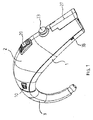
- a hearing aid which comprises a housing divided into two shell parts, a first shell part 1 and a second shell part 2. At the upper end of the housing a hook is mounted in an adapter part. An acoustic inlet opening 10 appears as well as a volume control 20, an activating button 23 and a battery drawer 27. An aperture 38 for accessing a battery terminal appears.
- the hook 3 comprises a circumferential recess 4 at the coupling end. It appears that the hook is mounted in an adapter part 5, which is mounted in an aperture in the first shell part 1 and is held in place by means of two flexible legs 6,7 having at their outer ends barbs cooperating with internal shoulders around the aperture 8 in the first shell part.
- the opposite end of the adapter 5 comprises four flexible wall parts separated by incisions and having internal barbs adapted to cooperate with the recess 4 in the hook 3.
- the first shell part comprises an acoustic inlet channel which at the outer end is branched into two opposed acoustic inlet openings 10,11 located at the sides of the first shell part.
- a thin protruding wall 12 surrounds each inlet opening.
- the channel faces a cavity 13 for holding a microphone suspension 14 which holds the microphone 15. Beneath the cavity 13 for holding the microphone suspension and the microphone the above-mentioned aperture 8 for the hook adapter is situated.
- a receiver 17 is adapted to be placed in a receiver suspension 16, which is inserted into the aperture and into the adapter. The outer end of the suspension forms a seal against the hook 3 when this is mounted in the hook adapter.
- first shell part holding means for receiving and holding a circuitry board 18 which on its side holds an amplifier 19, a volume control 20, a telecoil (not visible), programming terminals 21 and a switch 22 adapted to be activated by the activating button 23.
- These holding means comprise holding slots 33,34 (see FIG. 3 ) for the end areas of the board at one side edge of this. This means that the board is fixed in transversal as well as longitudinal translation and may only be inserted and removed in a direction parallel to the board plane. Between the slots apertures 49 for the programming terminals on the circuitry board are provided for allowing access to these from the outer surface of the housing.
- a locking recess 50 is provided at the end of the first shell part.
- a recess 29 is provided for receiving a terminal wall 30 being provided with terminals 31,32 for contacting the battery and further terminal 36,37 for external access through apertures 38,39.
- the second shell part comprise apertures 24 for receiving and surrounding the protruding walls 12 around the acoustic inlets 10,11 on the first shell part.
- a locking arm 25 having a barb 26 is provided at the opposite end of the second shell part.
- This locking arm 25and the barb 26 together with the apertures 24 at the opposite end of the second shell part and the protruding wall 12 and the locking recess 50 on the first shell part forms the releasable locking means of the two shell parts.
- the battery drawer is mounted to be pivotable around a shaft 28.
- the two shell parts may be dismantled using a tool which comprises two arms adapted to be inserted between the first and the second shell part in the area where these are mutually connected at the acoustic inlets. Upon insertion the second shell part will be expanded to a state where this may be lifted away from the protruding wall parts and hereby may be released from the first shell part.
- the wall elements 12 surrounding the inlet openings 10,11 appear. It appears that the lower edge of the wall element will retain the second shell part against an upward directed movement.
- a recess 50 is provided, which is adapted for receiving a barb 26 on an arm 25 of the second shell part.
- guide rails 40,41 on the first shell part appear as well as stays 42,43 for increasing the rigidity of the construction, especially against pressure from the side, These elements 40-43 cooperate with apertures or recesses 44-47 in the second shell part.
- Guide taps for the terminal wall in the recess 29 appears as well.
- the arm 25 with the locking barb 26 appears. Furthermore the holes 44,45 for receiving the stays of the first shell part appears as well as the recesses 46,47 for receiving the guide rails of the first shell part. Furthermore a holding means 48 for holding the circuitry board at a side edge opposite the one held in the first shell part is provided in the second shell part.
- the assembling of the hearing aid is carried out by fixing the first shell part and hereafter placing the microphone suspension in the aperture adapted for this purpose, as shown in FIG. 5 .
- the microphone is placed in the microphone suspension as shown in FIG. 6 .
- the receiver suspension is mounted and the receiver is mounted in the receiver suspension as shown in FIG 7 .
- the terminal wall is mounted in the first shell part, as shown in FIG. 8 , and the circuitry board is inserted, as shown in FIG. 9 .
- the electrical connection between the circuitry board and the terminals is achieved by abutment of the free ends of the terminals with contact pads on the circuitry board.
- the second shell part is mounted on the first shell part by snap locking as shown in FIG. 10 .
- the battery drawer is mounted in the second shell part and the hook is mounted in the housing as shown in FIG. 11 .
- the hearing aid described in the foregoing may be assembled at least partly in automated manufacturing equipment comprising one or more robots. This will significantly reduce the labor intensive manufacturing process, which is normally used in the hearing aid manufacturing. Even when not using robots the construction of the hearing aid as described in the foregoing provides a significant reduction in the manual assembling process.
Landscapes
- Engineering & Computer Science (AREA)
- Signal Processing (AREA)
- Health & Medical Sciences (AREA)
- General Health & Medical Sciences (AREA)
- Neurosurgery (AREA)
- Otolaryngology (AREA)
- Physics & Mathematics (AREA)
- Acoustics & Sound (AREA)
- Manufacturing & Machinery (AREA)
- Structure Of Receivers (AREA)
- Casings For Electric Apparatus (AREA)
- Finger-Pressure Massage (AREA)
- Details Of Audible-Bandwidth Transducers (AREA)
- Headphones And Earphones (AREA)
- Table Equipment (AREA)
- Toys (AREA)
- Battery Mounting, Suspending (AREA)
- Adornments (AREA)
Abstract
Description
- The invention relates to a hearing aid comprising a housing containing a microphone, an amplifier, a receiver and a battery for power supply, the housing comprising a front end and a rear end, a top area and a bottom area, where at the top area a hook is placed for transmittal of acoustic signals from the receiver into the ear of the user.
- Such hearing aids are well known within the art as so-called BTE hearing aids. The front end is the end, which abuts the ear of the user. The manufacturing of such hearing aids is normally carried out by a manual assembling process. It is obvious that the assembling process is a cost and time-consuming process, as the many tiny parts require a significant accuracy.
- Usually the hearing aid of this type comprises a housing, which has lines of separation extending at the front end and at the rear end. This type of housing makes the assembling process rather cumbersome and time consuming since the inner housing is poorly accessible. This means that the initial price of the hearing aid becomes high as well as the cost of subsequent repair necessitating a separation of the two housing parts.
- An example of such hearing aids is given in
US patent US 4 965 831 . - A further previously known hearing aid comprises a frame, which carries the operating parts of the hearing aid. It is clear that such a frame applies more weight to the hearing and therefore in undesirable.
- The objective of the present invention is to provide a hearing aid, which facilitates the assembling process and furthermore makes an at least partly automated assembly possible without increasing the weight of the hearing aid.
- According to the invention this is obtained by a hearing aid of the type described in the introductory part of the description where the housing comprises two connectable and detachable parts having lines of separation extending at least partly between top and bottom at both sides of the housing between the front area and the rear area, where in the front part means are provided for holding at least the amplifier circuitry board.
- One of the parts comprises mutually separated protruding holding means for receiving a side edge of the circuitry board and the opposed housing part is adapted to hold the side edge of the amplifier or the circuitry board opposite the side received in the first part.
- Since the front part is separated as suggested and since this part comprises means for holding the microphone, the amplifier and the receiver it has been made possible to access the holding means much easier using manual assembly methods and also using automated assembly machinery such as industrial robots. The result of this is a significant decrease in time consuming by manual assembly hereby obtaining a more cost effective assembly process and furthermore the possibility of using a assembly machinery hereby also obtaining a more cost effective assembly. In both cases the final product will be producible with lower costs hereby increasing the competitiveness of the hearing aid. The self-sustaining character of the hearing aid housing maintains the desirable low weight.
- In a preferred embodiment part further comprises means for holding the microphone possibly in a microphone suspension.
- In a further preferred embodiment the front part further comprises means for holding the receiver, possibly in a receiver suspension.
- Preferably the means for holding the circuitry board comprises at least one slot for receiving a side edge of the circuitry board.
- The rear part is adapted to hold the side edge opposite the one received in the front part.
- The invention will be explained more detailed in the following with reference to the drawings.
-
-
FIG. 1 is a perspective view of a BTE hearing aid according to the invention; -
FIG. 2 is an exploded view of the hearing aid shown inFIG. 1 ; -
FIG. 3 is a top view of the front part of the housing; -
FIG. 4 is a bottom view of the rear part of the housing; -
FIGS. 5-11 are perspective views of the front part of the housing during the assembling process; - From
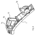
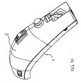
FIG. 1 a hearing aid appears, which comprises a housing divided into two shell parts, afirst shell part 1 and asecond shell part 2. At the upper end of the housing a hook is mounted in an adapter part. Anacoustic inlet opening 10 appears as well as avolume control 20, an activatingbutton 23 and abattery drawer 27. Anaperture 38 for accessing a battery terminal appears. - From
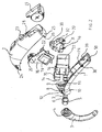
FIG. 2 an exploded view of the hearing aid shown inFIG. 1 appears. The hook 3 comprises a circumferential recess 4 at the coupling end. It appears that the hook is mounted in an adapter part 5, which is mounted in an aperture in thefirst shell part 1 and is held in place by means of twoflexible legs 6,7 having at their outer ends barbs cooperating with internal shoulders around theaperture 8 in the first shell part. The opposite end of the adapter 5 comprises four flexible wall parts separated by incisions and having internal barbs adapted to cooperate with the recess 4 in the hook 3. - The first shell part comprises an acoustic inlet channel which at the outer end is branched into two opposed
acoustic inlet openings protruding wall 12 surrounds each inlet opening. At the inner end the channel faces acavity 13 for holding amicrophone suspension 14 which holds themicrophone 15. Beneath thecavity 13 for holding the microphone suspension and the microphone the above-mentionedaperture 8 for the hook adapter is situated. Areceiver 17 is adapted to be placed in areceiver suspension 16, which is inserted into the aperture and into the adapter. The outer end of the suspension forms a seal against the hook 3 when this is mounted in the hook adapter. - In the first shell part holding means are provided for receiving and holding a
circuitry board 18 which on its side holds anamplifier 19, avolume control 20, a telecoil (not visible), programming terminals 21 and aswitch 22 adapted to be activated by the activatingbutton 23. These holding means compriseholding slots 33,34 (seeFIG. 3 ) for the end areas of the board at one side edge of this. This means that the board is fixed in transversal as well as longitudinal translation and may only be inserted and removed in a direction parallel to the board plane. Between the slots apertures 49 for the programming terminals on the circuitry board are provided for allowing access to these from the outer surface of the housing. At the end of the first shell part alocking recess 50 is provided. Arecess 29 is provided for receiving aterminal wall 30 being provided withterminals further terminal apertures - The second shell part comprise
apertures 24 for receiving and surrounding theprotruding walls 12 around theacoustic inlets locking arm 25 having abarb 26 is provided. This locking arm 25and thebarb 26 together with theapertures 24 at the opposite end of the second shell part and theprotruding wall 12 and the locking recess 50 on the first shell part forms the releasable locking means of the two shell parts. In the second shell part the battery drawer is mounted to be pivotable around ashaft 28. The two shell parts may be dismantled using a tool which comprises two arms adapted to be inserted between the first and the second shell part in the area where these are mutually connected at the acoustic inlets. Upon insertion the second shell part will be expanded to a state where this may be lifted away from the protruding wall parts and hereby may be released from the first shell part. - From
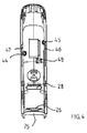
FIG. 3 thewall elements 12 surrounding theinlet openings recess 50 is provided, which is adapted for receiving abarb 26 on anarm 25 of the second shell part. Furthermoreguide rails recess 29 appears as well. - From
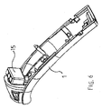
FIG. 4 thearm 25 with thelocking barb 26 appears. Furthermore theholes recesses - The assembling of the hearing aid is carried out by fixing the first shell part and hereafter placing the microphone suspension in the aperture adapted for this purpose, as shown in
FIG. 5 . Afterwards the microphone is placed in the microphone suspension as shown inFIG. 6 . The receiver suspension is mounted and the receiver is mounted in the receiver suspension as shown inFIG 7 . Following that the terminal wall is mounted in the first shell part, as shown inFIG. 8 , and the circuitry board is inserted, as shown inFIG. 9 . The electrical connection between the circuitry board and the terminals is achieved by abutment of the free ends of the terminals with contact pads on the circuitry board. Afterwards the second shell part is mounted on the first shell part by snap locking as shown inFIG. 10 . The battery drawer is mounted in the second shell part and the hook is mounted in the housing as shown inFIG. 11 . - The hearing aid described in the foregoing may be assembled at least partly in automated manufacturing equipment comprising one or more robots. This will significantly reduce the labor intensive manufacturing process, which is normally used in the hearing aid manufacturing. Even when not using robots the construction of the hearing aid as described in the foregoing provides a significant reduction in the manual assembling process.
Claims (5)
- A hearing aid comprising a housing containing a microphone, an amplifier, a receiver and a battery for power supply, the housing comprising a front end and a rear end, a top area and a bottom area, where at the top area a hook is placed for transmittal of acoustic signals from the receiver into the ear of the user, where the housing comprises two connectable and detachable parts having lines of separation extending at least partly between top and bottom at both sides of the housing between the front end and the rear end, where means are provided for holding the amplifier in one of the two parts, characterized in that one of the parts comprises mutually separated protruding holding means for receiving a side edge of the circuitry board and that the opposed housing part is adapted to hold the side edge of the amplifier or the circuitry board opposite the side received in the first part.
- A hearing aid according to claim 1, characterized in that one of the parts further comprises means for holding the microphone, possibly in a microphone suspension.
- A hearing aid according to claim 1 or 2, characterized in that on of the parts further comprises means for holding the receiver, possibly in a receiver suspension.
- A hearing aid according to claim 1, 2 or 3, characterized in that the means for holding the circuitry board comprises at least one slot for receiving a side edge of the circuitry board.
- A hearing aid according to any of the claims 1-4, characterized in that the amplifier, the circuitry board, the microphone and/or the receiver are/is received in the front part.
Applications Claiming Priority (3)
| Application Number | Priority Date | Filing Date | Title |
|---|---|---|---|
| DK126898 | 1998-10-07 | ||
| DKPA199801268 | 1998-10-07 | ||
| PCT/DK1999/000533 WO2000021334A2 (en) | 1998-10-07 | 1999-10-07 | Behind-the-ear hearing aid |
Publications (2)
| Publication Number | Publication Date |
|---|---|
| EP1120010A2 EP1120010A2 (en) | 2001-08-01 |
| EP1120010B1 true EP1120010B1 (en) | 2010-04-21 |
Family
ID=8102947
Family Applications (1)
| Application Number | Title | Priority Date | Filing Date |
|---|---|---|---|
| EP99970258A Expired - Lifetime EP1120010B1 (en) | 1998-10-07 | 1999-10-07 | A hearing aid |
Country Status (7)
| Country | Link |
|---|---|
| US (1) | US6700983B1 (en) |
| EP (1) | EP1120010B1 (en) |
| AT (1) | ATE465604T1 (en) |
| AU (1) | AU5969199A (en) |
| DE (1) | DE69942276D1 (en) |
| DK (1) | DK1120010T3 (en) |
| WO (1) | WO2000021334A2 (en) |
Families Citing this family (29)
| Publication number | Priority date | Publication date | Assignee | Title |
|---|---|---|---|---|
| US6694034B2 (en) * | 2000-01-07 | 2004-02-17 | Etymotic Research, Inc. | Transmission detection and switch system for hearing improvement applications |
| FI4930U1 (en) * | 2001-01-31 | 2001-05-23 | Savox Solutions Oy Ab | The headphone / microphone |
| US7102217B2 (en) * | 2003-04-09 | 2006-09-05 | Micron Technology, Inc. | Interposer substrates with reinforced interconnect slots, and semiconductor die packages including same |
| EP1692918B1 (en) | 2003-12-05 | 2018-08-15 | Oticon A/S | Communication device with microphone |
| WO2005097255A1 (en) * | 2004-04-02 | 2005-10-20 | Advanced Bionics Corporation | Electric and acoustic stimulation fitting systems and methods |
| DE102004054927A1 (en) * | 2004-11-13 | 2006-06-01 | Hansaton Akustik Gmbh | Hearing aid with volume control wheel |
| US20090222064A1 (en) * | 2005-07-08 | 2009-09-03 | Advanced Bionics, Llc | Autonomous Autoprogram Cochlear Implant |
| US8265765B2 (en) | 2005-12-08 | 2012-09-11 | Cochlear Limited | Multimodal auditory fitting |
| US20060171550A1 (en) * | 2006-03-17 | 2006-08-03 | Audina Hearing Instruments, Inc. | BTE hearing aid component and hearing aid comprising same |
| CN101395960B (en) | 2006-03-21 | 2013-02-20 | 唯听助听器公司 | Interchangeable attachment means for attaching a conductor to a hearing aid |
| US8818517B2 (en) | 2006-05-05 | 2014-08-26 | Advanced Bionics Ag | Information processing and storage in a cochlear stimulation system |
| US7864968B2 (en) * | 2006-09-25 | 2011-01-04 | Advanced Bionics, Llc | Auditory front end customization |
| US7995771B1 (en) | 2006-09-25 | 2011-08-09 | Advanced Bionics, Llc | Beamforming microphone system |
| USD579567S1 (en) * | 2007-03-21 | 2008-10-28 | Oticon A/S | Hearing aid |
| DK2023663T3 (en) * | 2007-08-07 | 2011-05-30 | Bernafon Ag | BTE hearing aid with interchangeable cover |
| WO2010047658A1 (en) * | 2008-10-23 | 2010-04-29 | Siemens Medical Instruments Pte Ltd | Hearing aid |
| EP2353303B1 (en) * | 2008-12-02 | 2020-11-04 | Sonova AG | Modular hearing device |
| DE102009011292A1 (en) * | 2009-03-02 | 2010-09-09 | Siemens Medical Instruments Pte. Ltd. | Hearing device with an acoustic unit and a shell part |
| AU335458S (en) * | 2010-08-24 | 2011-03-17 | Oticon As | Hearing aid |
| DE102011007848A1 (en) * | 2011-04-21 | 2012-10-25 | Siemens Medical Instruments Pte. Ltd. | Reduction of acoustic feedback by vibration shortening of the hearing aid |
| DE102014200917A1 (en) * | 2014-01-20 | 2015-07-23 | Siemens Medical Instruments Pte. Ltd. | BTE hearing aid with housing and sound tube |
| EP3422741B1 (en) * | 2014-04-07 | 2020-06-17 | Oticon A/s | Hearing aid device having battery drawer |
| DK3145219T3 (en) * | 2015-09-21 | 2021-07-26 | Oticon As | HEARING DEVICE |
| USD859662S1 (en) | 2017-05-24 | 2019-09-10 | Oticon Medical A/S | Hearing aid device |
| USD845487S1 (en) * | 2018-02-05 | 2019-04-09 | Weifeng Zheng | Hearing aid |
| CN111615040B (en) * | 2020-05-28 | 2022-02-25 | 美特科技(苏州)有限公司 | Medical hearing aid earphone |
| JP1680225S (en) * | 2020-08-18 | 2021-03-01 | ||
| EP4270994A1 (en) * | 2022-04-29 | 2023-11-01 | Starkey Laboratories, Inc. | Ear-wearable device with foreign material trap |
| EP4694208A1 (en) * | 2024-04-11 | 2026-02-11 | Shenzhen Shokzhear Co., Ltd. | Wearable device |
Family Cites Families (9)
| Publication number | Priority date | Publication date | Assignee | Title |
|---|---|---|---|---|
| DE7918029U1 (en) * | 1979-06-22 | 1980-12-04 | Siemens Ag, 1000 Berlin Und 8000 Muenchen | SMALL HEATER |
| DE8428516U1 (en) * | 1984-09-27 | 1986-01-23 | Siemens AG, 1000 Berlin und 8000 München | Hearing aid to be worn behind the ear |
| DE3639402A1 (en) * | 1986-11-18 | 1988-05-19 | Siemens Ag | METHOD FOR THE PRODUCTION OF A MULTI-LAYERED CIRCUIT BOARD AND THE CIRCUIT BOARD PRODUCED THEREOF |
| DE8713086U1 (en) * | 1987-09-29 | 1989-01-26 | Siemens AG, 1000 Berlin und 8000 München | Hearing aid with housing |
| DE8713088U1 (en) * | 1987-09-29 | 1989-01-26 | Siemens AG, 1000 Berlin und 8000 München | Hearing aid with battery charger |
| CA2014960C (en) * | 1990-04-19 | 1995-07-25 | Horst Arndt | Modular hearing aid |
| DE9408054U1 (en) * | 1993-06-04 | 1994-07-14 | Siemens Audiologische Technik Gmbh, 91058 Erlangen | Hearing aid |
| US6041128A (en) * | 1994-01-31 | 2000-03-21 | Rion Kabushiki Kaisha | Battery receiving chamber and hearing aid |
| DE19514360C1 (en) * | 1995-04-18 | 1996-02-22 | Siemens Audiologische Technik | Behind-the-ear hearing aid |
-
1999
- 1999-10-07 AU AU59691/99A patent/AU5969199A/en not_active Abandoned
- 1999-10-07 EP EP99970258A patent/EP1120010B1/en not_active Expired - Lifetime
- 1999-10-07 DK DK99970258.2T patent/DK1120010T3/en active
- 1999-10-07 US US09/806,998 patent/US6700983B1/en not_active Expired - Fee Related
- 1999-10-07 DE DE69942276T patent/DE69942276D1/en not_active Expired - Lifetime
- 1999-10-07 AT AT99970258T patent/ATE465604T1/en not_active IP Right Cessation
- 1999-10-07 WO PCT/DK1999/000533 patent/WO2000021334A2/en not_active Ceased
Also Published As
| Publication number | Publication date |
|---|---|
| ATE465604T1 (en) | 2010-05-15 |
| WO2000021334A2 (en) | 2000-04-13 |
| AU5969199A (en) | 2000-04-26 |
| US6700983B1 (en) | 2004-03-02 |
| DK1120010T3 (en) | 2010-08-02 |
| EP1120010A2 (en) | 2001-08-01 |
| DE69942276D1 (en) | 2010-06-02 |
| WO2000021334A3 (en) | 2000-07-13 |
Similar Documents
| Publication | Publication Date | Title |
|---|---|---|
| EP1120010B1 (en) | A hearing aid | |
| EP1120009B1 (en) | A hearing aid | |
| US5008943A (en) | Modular hearing aid with lid hinged to faceplate | |
| US5201008A (en) | Modular hearing aid with lid hinged to faceplate | |
| US6731770B1 (en) | Behind-the-ear hearing aid and surface-mounted module for this type of hearing aid | |
| EP1853091B9 (en) | Hearing aid with miniature loudspeaker | |
| US7254247B2 (en) | Hearing aid with a microphone in the battery compartment lid | |
| CA2377449C (en) | Behind-the-ear hearing device | |
| US7407035B2 (en) | Split shell system and method for hearing aids | |
| US4815138A (en) | In-the-ear hearing-aid with pivotable inner and outer sections | |
| CA1240027A (en) | Hearing aid and apparatus used therein | |
| JP2002524888A (en) | Rear ear hearing aid | |
| WO1998047319A1 (en) | A compact modular in-the-ear hearing aid | |
| WO2000021336A2 (en) | A hearing aid | |
| JP4246432B2 (en) | Ear-mounted hearing aid | |
| US7076074B2 (en) | Bearing of an electroacoustic miniature transducer in a device, particularly a hearing aid device, as well as an electroacoustic miniature transducer | |
| EP1483938B1 (en) | Microphone and battery configuration for hearing instruments | |
| CN110972049B (en) | Hearing aid with loop antenna | |
| CA2063806A1 (en) | In-the-ear hearing aid with sound compensating channel | |
| EP1692918B1 (en) | Communication device with microphone | |
| US20030089548A1 (en) | In the ear hearing aid | |
| CN106993252B (en) | Hearing device | |
| EP4686226A1 (en) | An assembly method for a hearing device and a hearing device | |
| US20180376259A1 (en) | Hearing device and connecting clip for a hearing device | |
| US7359524B2 (en) | Hearing aid assembly |
Legal Events
| Date | Code | Title | Description |
|---|---|---|---|
| PUAI | Public reference made under article 153(3) epc to a published international application that has entered the european phase |
Free format text: ORIGINAL CODE: 0009012 |
|
| 17P | Request for examination filed |
Effective date: 20010507 |
|
| AK | Designated contracting states |
Kind code of ref document: A2 Designated state(s): AT BE CH CY DE DK ES FI FR GB GR IE IT LI LU MC NL PT SE |
|
| RAP1 | Party data changed (applicant data changed or rights of an application transferred) |
Owner name: OTICON A/S |
|
| GRAP | Despatch of communication of intention to grant a patent |
Free format text: ORIGINAL CODE: EPIDOSNIGR1 |
|
| GRAS | Grant fee paid |
Free format text: ORIGINAL CODE: EPIDOSNIGR3 |
|
| GRAA | (expected) grant |
Free format text: ORIGINAL CODE: 0009210 |
|
| AK | Designated contracting states |
Kind code of ref document: B1 Designated state(s): AT BE CH CY DE DK ES FI FR GB GR IE IT LI LU MC NL PT SE |
|
| REG | Reference to a national code |
Ref country code: GB Ref legal event code: FG4D |
|
| REG | Reference to a national code |
Ref country code: CH Ref legal event code: NV Representative=s name: SCHNEIDER FELDMANN AG PATENT- UND MARKENANWAELTE Ref country code: CH Ref legal event code: EP |
|
| REG | Reference to a national code |
Ref country code: IE Ref legal event code: FG4D |
|
| REF | Corresponds to: |
Ref document number: 69942276 Country of ref document: DE Date of ref document: 20100602 Kind code of ref document: P |
|
| REG | Reference to a national code |
Ref country code: DK Ref legal event code: T3 |
|
| REG | Reference to a national code |
Ref country code: NL Ref legal event code: VDEP Effective date: 20100421 |
|
| PG25 | Lapsed in a contracting state [announced via postgrant information from national office to epo] |
Ref country code: SE Free format text: LAPSE BECAUSE OF FAILURE TO SUBMIT A TRANSLATION OF THE DESCRIPTION OR TO PAY THE FEE WITHIN THE PRESCRIBED TIME-LIMIT Effective date: 20100421 Ref country code: NL Free format text: LAPSE BECAUSE OF FAILURE TO SUBMIT A TRANSLATION OF THE DESCRIPTION OR TO PAY THE FEE WITHIN THE PRESCRIBED TIME-LIMIT Effective date: 20100421 Ref country code: ES Free format text: LAPSE BECAUSE OF FAILURE TO SUBMIT A TRANSLATION OF THE DESCRIPTION OR TO PAY THE FEE WITHIN THE PRESCRIBED TIME-LIMIT Effective date: 20100801 |
|
| PG25 | Lapsed in a contracting state [announced via postgrant information from national office to epo] |
Ref country code: FI Free format text: LAPSE BECAUSE OF FAILURE TO SUBMIT A TRANSLATION OF THE DESCRIPTION OR TO PAY THE FEE WITHIN THE PRESCRIBED TIME-LIMIT Effective date: 20100421 Ref country code: AT Free format text: LAPSE BECAUSE OF FAILURE TO SUBMIT A TRANSLATION OF THE DESCRIPTION OR TO PAY THE FEE WITHIN THE PRESCRIBED TIME-LIMIT Effective date: 20100421 |
|
| PG25 | Lapsed in a contracting state [announced via postgrant information from national office to epo] |
Ref country code: CY Free format text: LAPSE BECAUSE OF NON-PAYMENT OF DUE FEES Effective date: 20100421 |
|
| PG25 | Lapsed in a contracting state [announced via postgrant information from national office to epo] |
Ref country code: PT Free format text: LAPSE BECAUSE OF FAILURE TO SUBMIT A TRANSLATION OF THE DESCRIPTION OR TO PAY THE FEE WITHIN THE PRESCRIBED TIME-LIMIT Effective date: 20100823 |
|
| PLBE | No opposition filed within time limit |
Free format text: ORIGINAL CODE: 0009261 |
|
| STAA | Information on the status of an ep patent application or granted ep patent |
Free format text: STATUS: NO OPPOSITION FILED WITHIN TIME LIMIT |
|
| PG25 | Lapsed in a contracting state [announced via postgrant information from national office to epo] |
Ref country code: BE Free format text: LAPSE BECAUSE OF FAILURE TO SUBMIT A TRANSLATION OF THE DESCRIPTION OR TO PAY THE FEE WITHIN THE PRESCRIBED TIME-LIMIT Effective date: 20100421 |
|
| 26N | No opposition filed |
Effective date: 20110124 |
|
| PG25 | Lapsed in a contracting state [announced via postgrant information from national office to epo] |
Ref country code: IT Free format text: LAPSE BECAUSE OF FAILURE TO SUBMIT A TRANSLATION OF THE DESCRIPTION OR TO PAY THE FEE WITHIN THE PRESCRIBED TIME-LIMIT Effective date: 20100421 |
|
| PG25 | Lapsed in a contracting state [announced via postgrant information from national office to epo] |
Ref country code: GR Free format text: LAPSE BECAUSE OF FAILURE TO SUBMIT A TRANSLATION OF THE DESCRIPTION OR TO PAY THE FEE WITHIN THE PRESCRIBED TIME-LIMIT Effective date: 20100722 Ref country code: MC Free format text: LAPSE BECAUSE OF NON-PAYMENT OF DUE FEES Effective date: 20101031 |
|
| PG25 | Lapsed in a contracting state [announced via postgrant information from national office to epo] |
Ref country code: IE Free format text: LAPSE BECAUSE OF NON-PAYMENT OF DUE FEES Effective date: 20101007 |
|
| PG25 | Lapsed in a contracting state [announced via postgrant information from national office to epo] |
Ref country code: LU Free format text: LAPSE BECAUSE OF NON-PAYMENT OF DUE FEES Effective date: 20101007 |
|
| PGFP | Annual fee paid to national office [announced via postgrant information from national office to epo] |
Ref country code: DK Payment date: 20131021 Year of fee payment: 15 |
|
| PGFP | Annual fee paid to national office [announced via postgrant information from national office to epo] |
Ref country code: CH Payment date: 20131015 Year of fee payment: 15 Ref country code: FR Payment date: 20131031 Year of fee payment: 15 Ref country code: GB Payment date: 20131023 Year of fee payment: 15 Ref country code: DE Payment date: 20131022 Year of fee payment: 15 |
|
| REG | Reference to a national code |
Ref country code: DE Ref legal event code: R119 Ref document number: 69942276 Country of ref document: DE |
|
| REG | Reference to a national code |
Ref country code: CH Ref legal event code: PL |
|
| GBPC | Gb: european patent ceased through non-payment of renewal fee |
Effective date: 20141007 |
|
| PG25 | Lapsed in a contracting state [announced via postgrant information from national office to epo] |
Ref country code: DE Free format text: LAPSE BECAUSE OF NON-PAYMENT OF DUE FEES Effective date: 20150501 Ref country code: LI Free format text: LAPSE BECAUSE OF NON-PAYMENT OF DUE FEES Effective date: 20141031 Ref country code: CH Free format text: LAPSE BECAUSE OF NON-PAYMENT OF DUE FEES Effective date: 20141031 Ref country code: GB Free format text: LAPSE BECAUSE OF NON-PAYMENT OF DUE FEES Effective date: 20141007 |
|
| REG | Reference to a national code |
Ref country code: FR Ref legal event code: ST Effective date: 20150630 |
|
| REG | Reference to a national code |
Ref country code: DK Ref legal event code: EBP Effective date: 20141031 |
|
| PG25 | Lapsed in a contracting state [announced via postgrant information from national office to epo] |
Ref country code: FR Free format text: LAPSE BECAUSE OF NON-PAYMENT OF DUE FEES Effective date: 20141031 |
|
| PG25 | Lapsed in a contracting state [announced via postgrant information from national office to epo] |
Ref country code: DK Free format text: LAPSE BECAUSE OF NON-PAYMENT OF DUE FEES Effective date: 20141031 |