EP1341292A2 - Method of manufacturing the winding of an electric machine - Google Patents
Method of manufacturing the winding of an electric machine Download PDFInfo
- Publication number
- EP1341292A2 EP1341292A2 EP03004450A EP03004450A EP1341292A2 EP 1341292 A2 EP1341292 A2 EP 1341292A2 EP 03004450 A EP03004450 A EP 03004450A EP 03004450 A EP03004450 A EP 03004450A EP 1341292 A2 EP1341292 A2 EP 1341292A2
- Authority
- EP
- European Patent Office
- Prior art keywords
- electric conductor
- die
- electric
- corner
- conductor
- Prior art date
- Legal status (The legal status is an assumption and is not a legal conclusion. Google has not performed a legal analysis and makes no representation as to the accuracy of the status listed.)
- Granted
Links
Images





Classifications
-
- H—ELECTRICITY
- H02—GENERATION; CONVERSION OR DISTRIBUTION OF ELECTRIC POWER
- H02K—DYNAMO-ELECTRIC MACHINES
- H02K15/00—Processes or apparatus specially adapted for manufacturing, assembling, maintaining or repairing of dynamo-electric machines
- H02K15/04—Processes or apparatus specially adapted for manufacturing, assembling, maintaining or repairing of dynamo-electric machines of windings prior to their mounting into the machines
- H02K15/0414—Processes or apparatus specially adapted for manufacturing, assembling, maintaining or repairing of dynamo-electric machines of windings prior to their mounting into the machines the windings consisting of separate elements, e.g. bars, segments or half coils
-
- H—ELECTRICITY
- H02—GENERATION; CONVERSION OR DISTRIBUTION OF ELECTRIC POWER
- H02K—DYNAMO-ELECTRIC MACHINES
- H02K15/00—Processes or apparatus specially adapted for manufacturing, assembling, maintaining or repairing of dynamo-electric machines
- H02K15/04—Processes or apparatus specially adapted for manufacturing, assembling, maintaining or repairing of dynamo-electric machines of windings prior to their mounting into the machines
- H02K15/0414—Processes or apparatus specially adapted for manufacturing, assembling, maintaining or repairing of dynamo-electric machines of windings prior to their mounting into the machines the windings consisting of separate elements, e.g. bars, segments or half coils
- H02K15/0421—Processes or apparatus specially adapted for manufacturing, assembling, maintaining or repairing of dynamo-electric machines of windings prior to their mounting into the machines the windings consisting of separate elements, e.g. bars, segments or half coils and consisting of single conductors, e.g. hairpins
-
- Y—GENERAL TAGGING OF NEW TECHNOLOGICAL DEVELOPMENTS; GENERAL TAGGING OF CROSS-SECTIONAL TECHNOLOGIES SPANNING OVER SEVERAL SECTIONS OF THE IPC; TECHNICAL SUBJECTS COVERED BY FORMER USPC CROSS-REFERENCE ART COLLECTIONS [XRACs] AND DIGESTS
- Y10—TECHNICAL SUBJECTS COVERED BY FORMER USPC
- Y10T—TECHNICAL SUBJECTS COVERED BY FORMER US CLASSIFICATION
- Y10T29/00—Metal working
- Y10T29/49—Method of mechanical manufacture
- Y10T29/49002—Electrical device making
- Y10T29/49009—Dynamoelectric machine
-
- Y—GENERAL TAGGING OF NEW TECHNOLOGICAL DEVELOPMENTS; GENERAL TAGGING OF CROSS-SECTIONAL TECHNOLOGIES SPANNING OVER SEVERAL SECTIONS OF THE IPC; TECHNICAL SUBJECTS COVERED BY FORMER USPC CROSS-REFERENCE ART COLLECTIONS [XRACs] AND DIGESTS
- Y10—TECHNICAL SUBJECTS COVERED BY FORMER USPC
- Y10T—TECHNICAL SUBJECTS COVERED BY FORMER US CLASSIFICATION
- Y10T29/00—Metal working
- Y10T29/49—Method of mechanical manufacture
- Y10T29/49002—Electrical device making
- Y10T29/4902—Electromagnet, transformer or inductor
- Y10T29/49073—Electromagnet, transformer or inductor by assembling coil and core
-
- Y—GENERAL TAGGING OF NEW TECHNOLOGICAL DEVELOPMENTS; GENERAL TAGGING OF CROSS-SECTIONAL TECHNOLOGIES SPANNING OVER SEVERAL SECTIONS OF THE IPC; TECHNICAL SUBJECTS COVERED BY FORMER USPC CROSS-REFERENCE ART COLLECTIONS [XRACs] AND DIGESTS
- Y10—TECHNICAL SUBJECTS COVERED BY FORMER USPC
- Y10T—TECHNICAL SUBJECTS COVERED BY FORMER US CLASSIFICATION
- Y10T29/00—Metal working
- Y10T29/49—Method of mechanical manufacture
- Y10T29/49002—Electrical device making
- Y10T29/49117—Conductor or circuit manufacturing
- Y10T29/49124—On flat or curved insulated base, e.g., printed circuit, etc.
- Y10T29/49147—Assembling terminal to base
- Y10T29/49151—Assembling terminal to base by deforming or shaping
-
- Y—GENERAL TAGGING OF NEW TECHNOLOGICAL DEVELOPMENTS; GENERAL TAGGING OF CROSS-SECTIONAL TECHNOLOGIES SPANNING OVER SEVERAL SECTIONS OF THE IPC; TECHNICAL SUBJECTS COVERED BY FORMER USPC CROSS-REFERENCE ART COLLECTIONS [XRACs] AND DIGESTS
- Y10—TECHNICAL SUBJECTS COVERED BY FORMER USPC
- Y10T—TECHNICAL SUBJECTS COVERED BY FORMER US CLASSIFICATION
- Y10T29/00—Metal working
- Y10T29/53—Means to assemble or disassemble
- Y10T29/5313—Means to assemble electrical device
- Y10T29/53143—Motor or generator
- Y10T29/53148—Means to assemble commutator
-
- Y—GENERAL TAGGING OF NEW TECHNOLOGICAL DEVELOPMENTS; GENERAL TAGGING OF CROSS-SECTIONAL TECHNOLOGIES SPANNING OVER SEVERAL SECTIONS OF THE IPC; TECHNICAL SUBJECTS COVERED BY FORMER USPC CROSS-REFERENCE ART COLLECTIONS [XRACs] AND DIGESTS
- Y10—TECHNICAL SUBJECTS COVERED BY FORMER USPC
- Y10T—TECHNICAL SUBJECTS COVERED BY FORMER US CLASSIFICATION
- Y10T29/00—Metal working
- Y10T29/53—Means to assemble or disassemble
- Y10T29/5313—Means to assemble electrical device
- Y10T29/53143—Motor or generator
- Y10T29/53157—Means to stake wire to commutator or armature
Definitions
- the present invention relates to a method of manufacturing a winding of a rotary electric machine, such as a vehicular alternator mounted on passenger vehicles or trucks and a method of forming a dent on the winding.
- gaps are defined between electric conductors at portions where the electric conductors are adjacent in a radial direction at an axial end of the stator core to maintain electrical insulation therebetween.
- the gaps are formed by denting the electric conductor partially.
- a dent is formed on an electric conductor in a manner shown in Fig. 12A.
- An electric conductor 210 is pressed with a punch 202 in one direction in a die 200 so that its dimension along a pressing direction is reduced.
- the edges of the electric conductor, which are adjacent to inside corners of the die 200 are likely to deform, especially in a direction perpendicular to the pressing direction, as shown in Fig. 12B.
- slots are formed on a stator core by press working, and corners of the slots are curved. Therefore, when the electric conductor, the edges of which are deformed, is inserted in the slot, the electric conductor may breaks an insulator provided in the slot at the corners. Accordingly, it is difficult to maintain electrical insulation between the stator core and the electric conductors.
- the present invention is made in view of the above disadvantage and it is an object of the present invention to provide a method of manufacturing a winding of a rotary electric machine capable of maintaining electrical insulation between a stator core and electric conductors and a method of forming a dent on the winding.
- a method of manufacturing a winding includes a step of pressing a portion of an electric conductor with a punch in a predetermined direction in a condition that the electric conductor is held on a die, thereby reducing a dimension of the portion in the predetermined direction.
- the die has a predetermined shape for restricting deformation of a corner of the electric conductor.
- the die has a corner portion having a radius R1 of curvature that is smaller than a radius R0 of curvature of the corner of the electric conductor.
- the corner of the pressed portion is formed in the shape of the corner portion of the die.
- a vehicular alternator 1 of the embodiment includes a stator 2, a rotor 3, a housing 4, a rectifier 5 and the like.
- the rotor 3 which functions as a field magnet, rotates with a shaft 6, and includes a Lundell-type pole core 7, a field coil 8, slip rings 9, 10, a mixed flow fan 11, and a centrifugal fan 12 as an air blowing device.
- the shaft 6 is connected to a pulley 20, and rotated by an onboard engine (not shown) for driving a vehicle.
- the Lundell-type pole core 7 is constructed of a pair of pole cores.
- the Lundell-type pole core 7 includes a boss portion 71, which is fixed to the shaft 6, disc portions 72, which extend from the ends of the boss portion 71 in the radial direction, and twelve claw poles 73.
- the mixed flow fan 11 adjacent to the pulley 20 includes blades that are arranged at acute angles and blades that are arranged at right angles to a base plate 111, which is fixed to an end surface of the pole core 7 such as by welding.
- the centrifugal fan 12 on a side opposite to the pulley 20 only includes blades that are arranged at right angles to a base plate 121, which is fixed to an end surface of the pole core 7 such as by welding.
- the mixed flow fan 11 and the centrifugal fan 12 rotate with the rotor 3.
- the housing 4 includes a front housing 4a and a rear housing 4b.
- the housing 4 forms air inlet holes 41 on its axial end surfaces.
- the housing 4 forms cooling air outlet holes 42 on its shoulder portions corresponding to the radially outer peripheries of a first coil ends 31a and a second coil ends 31b of the stator 2.
- the front housing 4a and the rear housing 4b are fastened together with bolts 4c in a condition that the stator 2 and the rotor 3 are held therebetween.
- the rectifier 5 rectifies an AC voltage outputted from the stator 2 to a DC voltage.
- the rectifier 5 is fixed to the end on the side opposite to the pulley in the vehicular alternator 1.
- the stator 2 functions as an armature, and includes a stator winding 31, the stator core 32, and insulators 34.
- the stator winding 31 is constructed of the conductor segments 33 as a plurality of electric conductors that are arranged in slots 35 of the stator core 35.
- the insulators 34 provide electrical insulation between the stator core 32 and the stator winding 31.
- the stator core 32 has the plurality of slots 35 with openings on the inner diameter side for holding the multi-phase stator winding 31.
- thirty-six slots 35 are arranged at regular intervals for holding the three-phase stator winding 31.
- the four electric conductors are arranged in line in the slot 35 in order of inner end layer, inner middle layer, outer middle layer, and outer end layer from the inner diameter side in the radial direction of the stator core 32.
- the electric conductors are coated with insulating films 37 such as a polyamide-imide resin film.
- the electric conductors are connected in predetermined patterns, thereby constructing the stator winding 31.
- the electric conductors are connected through continuous turn portions placed on a side of the first coil end 31a and through end portions, which are opposite to the continuous turn portions, joined on a side of the second coil end 31b.
- One of the electric conductors in each slot 35 pairs up with another electric conductor in another slot 35 that is a predetermined pole-pitch away.
- an electric conductor in a specific layer in the slot 35 pairs up with an electric conductor in another layer in another slot 35 that is a predetermined pole-pitch away, in order to maintain gaps between the plurality of electric conductors at the coil ends and line them.
- an electric conductor 331a in the inner end layer in one slot pairs up with the electric conductor 331b in the outer end layer in another slot 35 that is one pole-pitch away in the clockwise direction of the stator core 32.
- an electric conductor 332a in the inner middle layer in one slot 35 pairs up with another electric conductor 332b in the outer middle layer in another slot 35 that is one pole-pitch away in the clockwise direction of the stator core 32.
- the paired electric conductors are connected through turn portions 331c, 332c at one of the axial ends of the stator core 32. Therefore, the continuous turn portion that connects the electric conductor in the outer middle layer and the electric conductor in the inner middle layer is surrounded by the continuous turn portion that connects the electric conductor in the outer end layer and the electric conductor in the inner end layer, at one of the axial ends of the stator core 32.
- the continuous portion of the paired electric conductors is surrounded by the continuous portion of another paired electric conductors held in the same slot, at the axial end of the stator core 32.
- the electric conductor 332a in the inner middle layer in the slot 35 also pairs up with an electric conductor 331a' in the inner end layer in another slot 35 that is one pole-pitch away in the clockwise direction of the stator core 32.
- an electric conductor 331b' in the outer end layer in the slot 35 pairs up with the electric conductor 332b in the outer middle layer in another slot 35 that is one pole-pitch away in the clockwise direction of the stator core 32.
- joint portions 331e', 332e connecting the electric conductor in the outer end layer and the electric conductor in the outer middle layer and joint portions 331d', 332d connecting the electric conductor in the inner end layer and the electric conductor in the inner middle layer are arranged in the radial direction of the stator core 32.
- Adjacent layer coil ends are formed by connecting the electric conductors in the outer end layer and the electric conductors in the outer middle layer, and by connecting the electric conductors in the inner end layer and the electric conductors in the inner middle layer. In this way, at the opposite axial end of the stator core 32, the connecting portions of the paired electric conductors are arranged without overlapping.
- the electric conductors are provided of U-shaped conductor segments that are produced by forming electric wires, which has substantially rectangular cross-sections and constant thickness, into predetermined shapes.
- the electric conductors in the inner end layer and the outer end layer are provided of a large segment 331.
- the large segment 331 is formed of an electric wire shaped into substantially a U-shape.
- the electric conductors in the inner middle layer and the outer middle layer are provided of a small segment 332.
- the small segment 332 is formed of an electric wire shaped into substantially a U-shape.
- the large segment 331 and the small segment 332 are included in the base conductor segment 33.
- the base conductor segments 33 are arranged regularly in the slots 35 so that a coil that turns twice around the stator core 32 is constructed.
- the conductor segments that include lead-out wires of the stator winding and turn portions connecting the first and the second laps are constructed of special shape conductor segments, which are in different shape from the base conductor segments 33.
- three special shape conductor segments are provided.
- the connection between the first and the second laps is made between the electric conductors in the outer layer and the inner layer.
- special shape coil ends are formed.
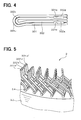
- Each base conductor segment 33 is set such that the turn portion 332c of the U-shaped small segment 332 is surrounded by the turn portion 331c of the U-shaped large segment 331, as shown in Fig. 4. Then, the base conductor segment 33 is twisted into a predetermined shape and is inserted into the slots from one axial end of the stator core 32 in the axial direction. Specifically, the electric conductor 331a, which is one of the electric conductors of the large segment 331, is inserted in the inner end layer in the slot 35 of the stator core 32. The electric conductor 332a, which is one of the electric conductors of the small segment 332, is inserted in the inner middle layer 32 of the same slot 35.
- the other electric conductor 331b of the large segment 331 is inserted in the outer end layer of another slot 35 that is one-pole pitch away in the clockwise of the stator core 32.
- the other electric conductor 332b of the small segment 332 is inserted in the outer middle layer in that another slot 35.
- Straight portions 331a, 332a, 332b' and 331b' which correspond to the above-described electric conductors, are arranged in line in the slot 35 in the order from the inner end layer in the radial direction, as shown in Fig. 2.
- the straight portions 332b', 331b' are the straight portions of the small segment 332 and the large segment 331, and are paired up with another straight portions in another slots that are one-pole pitch away, respectively.
- pressed portions (dents) 331g, 332g are formed in the large segment 331 and the small segment 332 adjacent to the ends opposite to the turn portions.
- the pressed portions 331g, 332g are formed by pressing portions of the large segment 331 and the small segment 332 in a predetermined direction (pressing direction) so that the dimensions at the pressed portion 331g, 332g are decreased in the pressing direction.
- the pressed portions 331g, 332g are to define gaps between opposing surfaces of the adjacent small segment 332 and large segment 331 in the stator winding 31.
- the pressed portions 331g, 332g are formed in a pressing step before the inserting step. The pressing step will be described later in detail.
- the straight portions 331a, 331b in the end layers are bent such that joint portions (ends) 331d, 331e are tilted for half-pole pitch (one and half slot in this embodiment) in a direction that the large segment 331 opens.
- the straight portions 332a, 332b in the middle layers are bent such that the joint portions (ends) 332d, 332e are tilted for half-pole pitch in the direction that the small segment 332 closes.
- the electric conductors adjacent in the radial direction are tilted in opposite directions along the circumference of the stator core 32.
- the above bending steps are repeated for all conductor segments 33 in the slots 35.
- the joint portion 331e' in the outer end layer and the joint portion 332e in the outer middle layer are joined by welding, such as ultrasonic welding, arc welding and brazing, and by other method, to have electrical continuity.
- the joint portion 332d in the inner middle layer and the joint portion 331d' in the inner end layer are joined in the similar manner. In this way, the second coil end 31b shown in Fig. 5 is produced.
- the pressing step is performed before the above-mentioned inserting step.
- the large segment 331 is placed such that a portion 331g to be pressed is held in a die 100. Then, the portion 331g is pressed by a punch 102 in one direction denoted by an arrow A1 in Fig. 6A.
- the direction is referred to as the pressing direction. Therefore, the dimension of the pressed portion 331g in the pressing direction A1 is reduced, thereby forming the dent.
- the die 100 has substantially a U-shaped cross-section and includes curved (arc-shaped) corner portions 100a to restrict deformation of corners 331h of the pressed portion 331g, which are inside of the die 100.
- the portion 331g is pressed, the material itself of the portion 331g moves in the pressing direction A1.
- the corners 331h of the portion 331g inside the die 100 moves in the pressing direction A1.
- the movement of the corners 331h are restricted by the curved corner portions 100a and formed in the shape of the curved corner portions 100a.
- the pressed portions 332g are formed in the small segments 332.
- gaps are defined at portions where the large segments 331 and the small segments 332 are crosses at the second coil end 31b, as denoted in hatched portions in Fig. 7.
- the slots 35 are formed by press working and the like, so the wall defining the slots 35 has curved corners 35a to 35d as shown in Fig. 2.
- the pressed portions 331g, 332g are formed in the pressing step and the corners 331h, 332h of the pressed portions 331g, 332g are formed in the shape of the curved corner portions 100a of the die 100.
- the pressing step is performed at least to the electric conductors arranged in the inner end layer and the outer end layer.
- a radius of the corner portion 100a of the die 100 corresponds to a radius of the corner 35a to 35d of the slots 35.
- pressure from the conductor segment 33 is uniformly applied to the insulator 34, thereby suppressing damages to the insulator 34.
- the radius of the corner portion 100a of the die 100 is determined in consideration of a thickness of the insulator 34. Therefore, the pressure applied to the insulator 34 is further uniformed, thereby preventing damage to the insulator 34. Accordingly, electrical insulations between the stator ore 32 and the conductor segments 33 are ensured.
- gaps can be defined between the insulator 34 and the wall of the slot 35 and between the conductor segments 33 and the insulator 34 on both the sides of the conductor segments 33 in the circumferential direction of the stator core 32.
- the total of the gap on each side is 80 ⁇ m, so it can restricts the pressed portion 331g, 332g to interfere with the insulator 34 and the slot 35 when the conductor segments 33 are inserted. Therefore, it makes easy to insert the conductor segments 33 in the slots 35 in which the insulator 34 is provided.
- the insulating films 37 at the joint portions 331d, 331e, 332d, 332e of the electric conductors are peeled off before the pressing step. Since the electric conductors have substantially rectangular-shaped cross-sections, it is easy to peel off the insulating films 37 on the joining surfaces.
- the die can be formed of three separate walls.
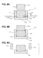
- a die 110 has a base wall 113 and side walls 111, 112 that are perpendicular to the base wall 113 to define the space in which the electric conductor 331, 332 is held.
- the side walls 111, 112 are detachable from the base wall 113.
- the base wall 113 includes a plate-like base portion 113a and protruding portions 113b, 113c protruding substantially perpendicular to the flat portion 113a.
- the base portion 113a forms curved corner portions 110a with the protruding portions 113b, 113c.
- Each corner portion 110a has a radius R1 that is greater than a radius R0 of the corners 331h, 332h of the electric conductors before the pressed portions 331g, 332g are formed.
- the electric conductor is placed in the space surrounded by the side walls 111, 112 and the base wall 113, as shown in Fig. 8A. Then, it is pressed with the punch 102 so that the dent (pressed portion 331g, 332g) is formed on the electric conductor, as shown in Fig. 8B (dent forming step). Further, the corners 331h, 332h of the electric conductor is formed in the shape of the curved corner portions. 110a.
- the electric conductor may be caught on the inner surfaces of the side walls 111, 112, and the base wall 113. Since the side walls 111, 112 can be removed from the base wall 113 in the direction that the material itself of the electric conductor, which is in contact with the side walls 111, 112, moves during the pressing. Therefore, the side walls 111, 112 are easily removed form the electric conductor.
- the electric conductor When the electric conductor is separated from the base wall 113, the electric conductor is moved in the direction that the surface of the electric conductor, which is in contact with the base wall 113, moves during the pressing. Therefore, the electric conductor is easily separated from the base wall 113.
- the insulating film 37 at the joint portions are easily peeled off, thereby easing manufacturability.
- the electric conductor having such the small radius R0 at corners since the corners 331h, 332h of the electric conductor are in press-contact with the corner portions 110a of the die 110, which has the radius R1 smaller than that R0 of the electric conductor, deformation over the radius R1 is restricted. Therefore, breakage of the insulating film 37 due to the excess deformation is suppressed, thereby maintaining the electrical insulation between the stator core 32 and the electric conductor.
- the electric conductor is easily inserted in the slot 35.
- the electric conductor is caught on the inner surfaces of the die 110 by the pressure, since the side walls 111, 112 can be removed from the base wall 113, the electric conductor is easily separated from the die 110.
- the base wall 113 can be removed from the side walls 111, 112 first. Then, the electric conductor can be separated from the side walls 111, 112. Also, the side walls 111, 112 can have the protruding portions protruding in the direction perpendicular to the pressing direction A1, and the corner portions 110a can be formed within the side walls 111, 112.
- the pressed portions 332g can be eliminated from the small segments 332. That is, the pressed portions 331g can be formed only to the large segment 331.
- the corner portions 100a, 110a can have any other shapes as long as the shape can restrict excess deformation of the conductor segments 33.
- the corner portions 100a, 110a can be sloped at 45 degrees with respect to the bottom surface of the die 100 by chamfering or have polygonal shapes.
- straight conductor segments can be used. The both ends of the straight conductor segments are joined at both axial ends of the stator core 32.
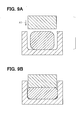
- the sides of the electric conductor is restricted with the side walls of the die, so the width of the pressed portion 331g, 332g does not generally change before and after pressing. However, it may be possible to increase the width while restricting deformation of the corner portions 331h, 332h, as shown in Figs. 9A and 9B.
- a width W3 of the pressed portion 331g, 332g may increase more than the width W2 (except for the thickness of the insulator) by pressing.
- the electric conductor such that the pressed direction A1 is in consistent with the circumferential direction of the stator core 32 (that is, in the condition that the electric conductor is turned 90 degrees from the position shown in Fig. 10.) After inserted, it is turned 90 degrees to the position shown in Fig. 10.
- the electric conductor can be arranged in the slot by turning after the insertion, thereby capable of forming the stator winding 31.
- Fig. 11 shows a case that plural electric conductors are provided in the slot 35 and those are arranged in line along the circumferential direction of the stator core 32.
- the total width TW5 of the electric conductors in the circumferential direction is greater than the width W2 of the slot 35 except for the thickness of the insulator 34.
- the total width of the pressed portions of some electric conductors and of non-pressed portions of other electric conductors is smaller than the width W2 of the slot 35 except for the thickness of the insulator 34.
- the electric conductors are inserted in the slot 35 separately.
- the electric conductors can be easily inserted in the slot, thereby capable of forming the stator winding 31.
- the present invention can be applied to manufacture a stator winding of rotary electric machines other than the vehicular alternator or windings other than the stator winding.
Landscapes
- Engineering & Computer Science (AREA)
- Manufacturing & Machinery (AREA)
- Power Engineering (AREA)
- Manufacture Of Motors, Generators (AREA)
- Windings For Motors And Generators (AREA)
- Insulation, Fastening Of Motor, Generator Windings (AREA)
- Synchronous Machinery (AREA)
Abstract
Description
Claims (21)
- A method of manufacturing a winding of a rotary electric machine, comprising:wherein the die (100) has a predetermined shape for restricting deformation of a corner (331h, 332h) of the pressed portion (331g, 332g) of the electric conductor.pressing a portion (331g, 332g) of an electric conductor, which has substantially a rectangular-shaped cross-section, with a punch (102) in a predetermined direction in a condition that the electric conductor is held on a die (100), thereby reducing a dimension of the pressed portion (331g, 332g) in the predetermined direction,
- The method according to claim 1, further comprising:inserting the electric conductors into slots (35) provided on a stator core (32) such that the electric conductors are layered in each of the slots (35) in a radial direction of the stator core (32);bending the electric conductors such that the pressed portion (331g, 332g) of one electric conductor is adjacent to the pressed portion (331g, 332g) of another electric conductor in the radial direction; andjoining ends of the electric conductors that are adjacent in the radial direction.
- The method according to claim 2, wherein the die (100, 110) includes a curved portion (100a, 110a).
- The method according to claim 3, wherein a wall of the stator core (32) that defines the slots (35) forms curved corners (35a, 35b, 35c, 35d), and the curved portion (100a, 110a) of the die (100, 110) has a radius of curvature that correspond to a radius of curvature of the curved corner (35a, 35b, 35c, 35d) of the slot (35).
- The method according to claim 3, wherein a wall of the stator core (32) that defines the slots (35) forms curved corners (35a, 35b, 35c, 35d), and the curved portion (100a, 110a ) of the die (100, 110) has a radius of curvature that is determined in consideration of a radius of the curved corner (35a, 35b, 35c, 35d) of the slot (35) and a thickness of an insulator (34) that is provided between the wall of the stator core (32) and the electric conductors.
- The method according to any one of claims 2 to 5, wherein the pressing step is performed at least to the electric conductors that are arranged in the innermost layer and the outermost layer in the slot.
- The method according to any one of claims 2 to 6, wherein the electric conductor is included in a conductor segment.
- The method according to claim 1, wherein the die (100, 10) has a curved portion (100a, 110a).
- The method according to claim 8,
wherein the die (100, 110) has substantially a U-shape including the curved portion (100a, 110a) therein,
wherein when the electric conductor is pressed in the die (100, 110), a corner (331h, 332h) of the electric conductor inside the die (100, 110) is formed in the shape of the curved portion (100a, 110a). - The method according to any one of claims 1, 8 and 9, further comprising:inserting the electric conductor in a slot (35) provided on a stator core (32) in a condition that the electric conductor is directed such that a second direction of the pressed portion (331g, 332g) is in consistent with a radial direction of the stator core (32), the second direction being perpendicular to the direction (A1) that the electric conductor is pressed, and a second dimension (W3) of the pressed portion (331g, 332g) in the second direction being greater than a dimension (W2) of the slot (35) in a circumferential direction of the stator core (32), andturning the electric conductor such that the second direction of the pressed portion (331g, 332g) is in the circumferential direction.
- The method according to any one of claims 1, 8 and 9, further comprising:wherein a total dimension (TW5) of the pressed portions (331g, 332g) in the circumferential direction is greater than a dimension (W2) of the slot (35) in the circumferential direction, and a total dimension of the pressed portions (331g, 332g) of some electric conductors and non-pressed portions of the other electric conductors in the slot is smaller than the dimension (W2) of the slot (35) in the circumferential direction.inserting the electric conductor in a slot (35) provided on a stator core (32) such that a plurality of electric conductors is arranged in a circumferential direction of the stator core (32) in the slot (35),
- A method of manufacturing a winding for a rotary electric machine, comprising:wherein the electric conductor has a radius R0 of curvature at its corner (331h, 332h) and the corner portion (100a, 110a) of the die (100, 110) has a radius R1 of curvature that is smaller than the radius R0 of the electric conductor,forming a dent (331g, 332g) on an electric conductor, which has substantially a rectangular-shaped cross-section and a surface of which being coated with an insulating film (37), in a condition that the electric conductor is held in a die (100, 110) having a corner portion (100a, 110a), thereby reducing a dimension of the electric conductor in a direction (A1) perpendicular to a longitudinal direction of the electric conductor, andwinding the electric conductors to cross each other at portions where the dents (331g, 332g) are formed,
wherein when the dent (331g, 332g) is formed, the corner (331h, 332h) of the electric conductor is formed in the shape of the corner portion (100a, 110a) of the die (100, 110). - The method according to claim 12, further comprising:wherein the insulating films (37) at the ends (331d, 331e, 332d, 332e) of the electric conductors are peeled before joined, and the electric conductors construct a conductor segment (33).joining the electric conductors at ends (331d, 331e, 332d, 332e)
- The method according to claim 12 or 13, wherein the die (110) includes a base wall (113) and side walls (111, 112) that are substantially perpendicular to the base wall (113) to define substantially a U-shaped space therein.
- The method according to claim 14, wherein the side walls (111, 112) are detachable from the base wall (113).
- The method according to claim 14 or 15, wherein the corner portions (110a) of the die is formed on the base wall (113).
- A method of forming a winding, comprising:wherein the electric conductor has a radius R0 of curvature at its corner (331h, 332h) and the corner portion (100a, 110a) of the die (100, 110) has a radius R1 of curvature that is smaller than the radius R0 of the electric conductor,forming a dent on an electric conductor in a condition that a portion (331g, 332g) of the electric conductor is held in a die (100, 110), thereby reducing a dimension of the portion (331g, 332g) in a direction (A1) perpendicular to a longitudinal direction of the electric conductor, the electric conductor being coated with an insulating film (37) and having substantially a rectangular-shaped cross-section,
wherein when the dent (331g, 332g) is formed, the corner (331h, 332h) of the portion is formed in the shape of the corner portion (100a, 110a) of the die (100, 110). - The method according to claim 17, wherein when the dent (331g, 332g) is formed, the radius R0 of the corner (331h, 332h) of the electric conductor is reduced.
- The method according to claim 17 or 18, wherein the die (110) includes a base wall (113) and side walls (111, 112) that are substantially perpendicular to the base wall (113) and detachable from the base wall (113).
- The method according to claim 19, wherein the corner portion (110a) of the die (110) is formed on the base wall (113).
- The method according to claim 19 or 20, further comprising:removing the side walls (111, 112) from the base wall (113) after the dent (331g, 332g) is formed, andseparating the electric conductor from the base wall (113).
Applications Claiming Priority (4)
| Application Number | Priority Date | Filing Date | Title |
|---|---|---|---|
| JP2002055781 | 2002-03-01 | ||
| JP2002055781 | 2002-03-01 | ||
| JP2003011912 | 2003-01-21 | ||
| JP2003011912A JP4019951B2 (en) | 2002-03-01 | 2003-01-21 | Manufacturing method of winding of rotating electrical machine and processing method of winding recess |
Publications (3)
| Publication Number | Publication Date |
|---|---|
| EP1341292A2 true EP1341292A2 (en) | 2003-09-03 |
| EP1341292A3 EP1341292A3 (en) | 2004-09-01 |
| EP1341292B1 EP1341292B1 (en) | 2009-08-26 |
Family
ID=27736581
Family Applications (1)
| Application Number | Title | Priority Date | Filing Date |
|---|---|---|---|
| EP03004450A Expired - Lifetime EP1341292B1 (en) | 2002-03-01 | 2003-02-27 | Method of manufacturing the winding of an electric machine |
Country Status (4)
| Country | Link |
|---|---|
| US (1) | US6971153B2 (en) |
| EP (1) | EP1341292B1 (en) |
| JP (1) | JP4019951B2 (en) |
| DE (1) | DE60328935D1 (en) |
Cited By (3)
| Publication number | Priority date | Publication date | Assignee | Title |
|---|---|---|---|---|
| EP1727260A3 (en) * | 2005-05-24 | 2007-11-14 | Hitachi, Ltd. | Joint structure of electric wire, stator of rotary electric machine, method for manufacturing the same |
| EP2424085A3 (en) * | 2010-08-27 | 2016-07-20 | Hamilton Sundstrand Corporation | Knurled multiple conductor windings |
| CN103825385B (en) * | 2012-11-15 | 2017-03-01 | 株式会社电装 | Stator winding and its manufacture method |
Families Citing this family (22)
| Publication number | Priority date | Publication date | Assignee | Title |
|---|---|---|---|---|
| JP3975947B2 (en) * | 2003-03-07 | 2007-09-12 | 株式会社デンソー | Manufacturing method of winding of rotating electric machine |
| DE102006002104A1 (en) * | 2006-01-17 | 2007-07-19 | Ltn Servotechnik Gmbh | Slip ring brush and slip ring unit equipped with it |
| JP4450235B2 (en) * | 2006-05-25 | 2010-04-14 | 株式会社デンソー | AC generator |
| JP4600373B2 (en) * | 2006-09-12 | 2010-12-15 | 株式会社デンソー | Vehicle alternator |
| JP5292973B2 (en) * | 2008-07-30 | 2013-09-18 | 株式会社デンソー | Rotating electric machine stator and rotating electric machine |
| SG172208A1 (en) | 2008-09-23 | 2011-07-28 | Aerovironment Inc | Motor air flow cooling |
| US8479377B2 (en) * | 2008-10-24 | 2013-07-09 | GM Global Technology Operations LLC | Methods and apparatus for a motor stator |
| JP5370245B2 (en) * | 2010-03-31 | 2013-12-18 | 株式会社デンソー | Manufacturing method of stator of rotating electric machine |
| US9226861B2 (en) | 2010-04-09 | 2016-01-05 | Gary Dean Lavon | Converting lines and methods for fabricating both taped and pant diapers comprising substantially identical chassis |
| US11980530B2 (en) | 2010-04-09 | 2024-05-14 | The Procter & Gamble Company | Taped and pant diapers comprising substantially identical chassis |
| US20130211357A1 (en) * | 2012-02-13 | 2013-08-15 | The Procter & Gamble Company | Absorbent articles comprising substantially identical chassis |
| JP5594544B2 (en) | 2012-07-31 | 2014-09-24 | 株式会社デンソー | Stator for rotating electric machine and method for manufacturing the same |
| JP5724984B2 (en) * | 2012-10-19 | 2015-05-27 | トヨタ自動車株式会社 | Rotating electric machine stator |
| CN105981266B (en) * | 2014-02-10 | 2019-06-25 | 三菱电机株式会社 | Rotating electrical machine and method for manufacturing the coil of the rotating electrical machine |
| JP6299438B2 (en) * | 2014-05-30 | 2018-03-28 | アイシン・エィ・ダブリュ株式会社 | Flat wire joining method |
| JP6402517B2 (en) * | 2014-07-14 | 2018-10-10 | 株式会社デンソー | Method for manufacturing conductor member, conductor member, stator, and motor |
| US10492962B2 (en) | 2015-09-18 | 2019-12-03 | The Procter & Gamble Company | Absorbent articles comprising substantially identical chassis and substantially identical flaps |
| JP6233384B2 (en) | 2015-10-29 | 2017-11-22 | トヨタ自動車株式会社 | Coil end joining method for stator segment coil |
| US11478840B2 (en) * | 2017-09-28 | 2022-10-25 | Nidec Corporation | Manufacturing method of wire rod, manufacturing apparatus of wire rod, wire rod, and motor |
| JP2020123997A (en) * | 2019-01-29 | 2020-08-13 | 日立オートモティブシステムズ株式会社 | Rotating electric machine and method of manufacturing rotating electric machine |
| CN110957866B (en) * | 2019-12-09 | 2025-04-04 | 浙江龙芯电驱动科技有限公司 | A device for twisting flat wire at the end of armature winding of flat wire motor |
| JP7496338B2 (en) * | 2021-09-13 | 2024-06-06 | ダイハツ工業株式会社 | How to remove the coating from rectangular wire |
Family Cites Families (11)
| Publication number | Priority date | Publication date | Assignee | Title |
|---|---|---|---|---|
| US53126A (en) * | 1866-03-13 | Improvement in broom-corn and sorghum strippers | ||
| JP3285459B2 (en) | 1995-01-30 | 2002-05-27 | 株式会社日立製作所 | Rotating electric machine and method for forming rotating armature for rotating electric machine |
| EP1237254B1 (en) * | 1997-05-26 | 2008-06-04 | Denso Corporation | Alternator for vehicle |
| JP3196738B2 (en) | 1998-09-11 | 2001-08-06 | 株式会社デンソー | Stator manufacturing apparatus and stator manufacturing method |
| JP3250533B2 (en) * | 1998-11-25 | 2002-01-28 | 株式会社デンソー | Stator for vehicle alternator and method of manufacturing the same |
| JP4029519B2 (en) | 1999-04-12 | 2008-01-09 | 株式会社デンソー | Vehicle alternator stator |
| JP4462392B2 (en) | 2000-02-23 | 2010-05-12 | 三菱電機株式会社 | Method of manufacturing an alternator stator |
| JP2002064028A (en) | 2000-08-16 | 2002-02-28 | Toyota Motor Corp | Coil, lead forming apparatus and lead forming method |
| JP3964116B2 (en) * | 2000-09-12 | 2007-08-22 | 三菱電機株式会社 | Rotating electric machine stator |
| JP3621636B2 (en) * | 2000-10-16 | 2005-02-16 | 三菱電機株式会社 | Alternator stator and method of manufacturing the same |
| JP3676707B2 (en) * | 2001-07-18 | 2005-07-27 | 三菱電機株式会社 | Stator for vehicle alternator and manufacturing method thereof |
-
2003
- 2003-01-21 JP JP2003011912A patent/JP4019951B2/en not_active Expired - Lifetime
- 2003-02-26 US US10/372,782 patent/US6971153B2/en not_active Expired - Lifetime
- 2003-02-27 EP EP03004450A patent/EP1341292B1/en not_active Expired - Lifetime
- 2003-02-27 DE DE60328935T patent/DE60328935D1/en not_active Expired - Lifetime
Cited By (5)
| Publication number | Priority date | Publication date | Assignee | Title |
|---|---|---|---|---|
| EP1727260A3 (en) * | 2005-05-24 | 2007-11-14 | Hitachi, Ltd. | Joint structure of electric wire, stator of rotary electric machine, method for manufacturing the same |
| US7615906B2 (en) | 2005-05-24 | 2009-11-10 | Hitachi, Ltd. | Joint structure of electric wire, stator of rotary electric machine, method for manufacturing the same |
| US7948140B2 (en) | 2005-05-24 | 2011-05-24 | Hitachi, Ltd. | Joint structure of electric wire, stator of rotary electric machine, method for manufacturing the same |
| EP2424085A3 (en) * | 2010-08-27 | 2016-07-20 | Hamilton Sundstrand Corporation | Knurled multiple conductor windings |
| CN103825385B (en) * | 2012-11-15 | 2017-03-01 | 株式会社电装 | Stator winding and its manufacture method |
Also Published As
| Publication number | Publication date |
|---|---|
| EP1341292A3 (en) | 2004-09-01 |
| US6971153B2 (en) | 2005-12-06 |
| EP1341292B1 (en) | 2009-08-26 |
| US20030163912A1 (en) | 2003-09-04 |
| JP4019951B2 (en) | 2007-12-12 |
| JP2003324885A (en) | 2003-11-14 |
| DE60328935D1 (en) | 2009-10-08 |
Similar Documents
| Publication | Publication Date | Title |
|---|---|---|
| EP1341292B1 (en) | Method of manufacturing the winding of an electric machine | |
| EP1369979B1 (en) | Method of manufacturing stator winding of rotary electric machine | |
| EP1381141B1 (en) | Rotary electric machine | |
| EP1376820A1 (en) | Stator of ac-generator and method of manufacturing the same | |
| EP1566878B1 (en) | Stator of a rotary electric machine and manufacturing method thereof | |
| EP1347559B1 (en) | Manufacturing method for a wound stator of a rotary electric machine | |
| EP0961385B1 (en) | A method of manufacturing a stator of an AC generator for a vehicle | |
| US20020092152A1 (en) | Method for manufacturing an alternator | |
| EP0824288A2 (en) | Manufacturing method for stator of motor | |
| EP1317047B1 (en) | Rotary electric machine and manufacturing method thereof | |
| JP2003259613A (en) | Method of manufacturing stator winding of rotating electric machine | |
| JP4066834B2 (en) | Manufacturing method of winding of rotating electric machine | |
| JP3511948B2 (en) | Method for manufacturing vehicle alternator and stator used therein | |
| EP1109299B1 (en) | Method for manufacturing an alternator | |
| JP4452984B2 (en) | Method for manufacturing stator winding of rotating electric machine |
Legal Events
| Date | Code | Title | Description |
|---|---|---|---|
| PUAI | Public reference made under article 153(3) epc to a published international application that has entered the european phase |
Free format text: ORIGINAL CODE: 0009012 |
|
| AK | Designated contracting states |
Kind code of ref document: A2 Designated state(s): AT BE BG CH CY CZ DE DK EE ES FI FR GB GR HU IE IT LI LU MC NL PT SE SI SK TR |
|
| AX | Request for extension of the european patent |
Extension state: AL LT LV MK RO |
|
| PUAL | Search report despatched |
Free format text: ORIGINAL CODE: 0009013 |
|
| AK | Designated contracting states |
Kind code of ref document: A3 Designated state(s): AT BE BG CH CY CZ DE DK EE ES FI FR GB GR HU IE IT LI LU MC NL PT SE SI SK TR |
|
| AX | Request for extension of the european patent |
Extension state: AL LT LV MK RO |
|
| RIC1 | Information provided on ipc code assigned before grant |
Ipc: 7H 02K 15/04 A Ipc: 7H 02K 3/50 B |
|
| 17P | Request for examination filed |
Effective date: 20040903 |
|
| 17Q | First examination report despatched |
Effective date: 20041228 |
|
| AKX | Designation fees paid |
Designated state(s): DE FR GB IT |
|
| RBV | Designated contracting states (corrected) |
Designated state(s): DE FR GB IT |
|
| GRAP | Despatch of communication of intention to grant a patent |
Free format text: ORIGINAL CODE: EPIDOSNIGR1 |
|
| GRAS | Grant fee paid |
Free format text: ORIGINAL CODE: EPIDOSNIGR3 |
|
| GRAA | (expected) grant |
Free format text: ORIGINAL CODE: 0009210 |
|
| AK | Designated contracting states |
Kind code of ref document: B1 Designated state(s): DE FR GB IT |
|
| REG | Reference to a national code |
Ref country code: GB Ref legal event code: FG4D |
|
| REF | Corresponds to: |
Ref document number: 60328935 Country of ref document: DE Date of ref document: 20091008 Kind code of ref document: P |
|
| PLBE | No opposition filed within time limit |
Free format text: ORIGINAL CODE: 0009261 |
|
| STAA | Information on the status of an ep patent application or granted ep patent |
Free format text: STATUS: NO OPPOSITION FILED WITHIN TIME LIMIT |
|
| 26N | No opposition filed |
Effective date: 20100527 |
|
| REG | Reference to a national code |
Ref country code: FR Ref legal event code: PLFP Year of fee payment: 14 |
|
| REG | Reference to a national code |
Ref country code: FR Ref legal event code: PLFP Year of fee payment: 15 |
|
| REG | Reference to a national code |
Ref country code: FR Ref legal event code: PLFP Year of fee payment: 16 |
|
| PGFP | Annual fee paid to national office [announced via postgrant information from national office to epo] |
Ref country code: GB Payment date: 20220223 Year of fee payment: 20 Ref country code: DE Payment date: 20220217 Year of fee payment: 20 |
|
| PGFP | Annual fee paid to national office [announced via postgrant information from national office to epo] |
Ref country code: IT Payment date: 20220218 Year of fee payment: 20 Ref country code: FR Payment date: 20220216 Year of fee payment: 20 |
|
| REG | Reference to a national code |
Ref country code: DE Ref legal event code: R071 Ref document number: 60328935 Country of ref document: DE |
|
| REG | Reference to a national code |
Ref country code: GB Ref legal event code: PE20 Expiry date: 20230226 |
|
| PG25 | Lapsed in a contracting state [announced via postgrant information from national office to epo] |
Ref country code: GB Free format text: LAPSE BECAUSE OF EXPIRATION OF PROTECTION Effective date: 20230226 |