EP1341287A2 - Rotor for rotating electric machine - Google Patents
Rotor for rotating electric machine Download PDFInfo
- Publication number
- EP1341287A2 EP1341287A2 EP03003274A EP03003274A EP1341287A2 EP 1341287 A2 EP1341287 A2 EP 1341287A2 EP 03003274 A EP03003274 A EP 03003274A EP 03003274 A EP03003274 A EP 03003274A EP 1341287 A2 EP1341287 A2 EP 1341287A2
- Authority
- EP
- European Patent Office
- Prior art keywords
- rotor
- cooling
- rotating electric
- conductors
- electric machine
- Prior art date
- Legal status (The legal status is an assumption and is not a legal conclusion. Google has not performed a legal analysis and makes no representation as to the accuracy of the status listed.)
- Withdrawn
Links
Images



Classifications
-
- H—ELECTRICITY
- H02—GENERATION; CONVERSION OR DISTRIBUTION OF ELECTRIC POWER
- H02K—DYNAMO-ELECTRIC MACHINES
- H02K3/00—Details of windings
- H02K3/04—Windings characterised by the conductor shape, form or construction, e.g. with bar conductors
- H02K3/24—Windings characterised by the conductor shape, form or construction, e.g. with bar conductors with channels or ducts for cooling medium between the conductors
-
- Y—GENERAL TAGGING OF NEW TECHNOLOGICAL DEVELOPMENTS; GENERAL TAGGING OF CROSS-SECTIONAL TECHNOLOGIES SPANNING OVER SEVERAL SECTIONS OF THE IPC; TECHNICAL SUBJECTS COVERED BY FORMER USPC CROSS-REFERENCE ART COLLECTIONS [XRACs] AND DIGESTS
- Y10—TECHNICAL SUBJECTS COVERED BY FORMER USPC
- Y10T—TECHNICAL SUBJECTS COVERED BY FORMER US CLASSIFICATION
- Y10T29/00—Metal working
- Y10T29/49—Method of mechanical manufacture
- Y10T29/49002—Electrical device making
- Y10T29/4902—Electromagnet, transformer or inductor
- Y10T29/49073—Electromagnet, transformer or inductor by assembling coil and core
Definitions
- the present invention relates to a rotor for a rotating electric machine, and a rotating electric machine.
- Fig. 6 is a fragmentary sectional view of rotor conductors 3 stacked in an end part of a rotor for a rotating electric machine. Turn insulations 13 are held between the adjacent turns of the stacked rotor conductors 3 to isolate the turns of the stacked rotor conductors 3 electrically from each other. Techniques relating to turn insulation are disclosed in Japanese Patent Laid-open No. 5-300683.
- a mean pressure that acts on the rotor conductor 3 is greater than a mean pressure that acts on the rotor conductor 3 before the cooling groove 10 is formed therein, and peak pressure are induced around the edges of the cooling groove 10 as typically represented by a stress distribution curve shown in Fig. 7.
- centrifugal force that acts on the rotor conductors increases with the increase of the size of the rotating electric machine or with the increase of energy density. Then the turn insulation 13 is damaged due to the peak pressure induced around the edges of the cooling groove 10, which deteriorates reliability.
- Rounding or chamfering the edges of the cooling groove 10 is an effective means for achieving the object.
- the greater the radius of the rounded edges or the chamfer of the chambered edges the greater the effect of rounding or chamfering on reducing the peak pressure, the great radius or chamfer increases the mean pressure.
- Fig. 8 shows the variation of the peak pressure and the mean pressure with the radius of a rounded edge. As shown in Fig.
- a desirable radius R for rounding or a desirable chamfer C for chamfering is in the range of 0.1 to 2.0 mm. In view of facility of radius and chamfer process, a desirable radius R for rounding or a desirable chamfer C for chamfering is in the range of 0.1 to 0.3 mm.
- the deformation of the open end of the cooling groove 10 is effective in reducing the peak pressure.
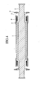
- Fig. 4 is a schematic longitudinal sectional view of a rotor for a rotating electric machine.
- the rotor has a rotor core 1, and a rotor shaft 2 coaxial with the rotor core 1 and longitudinally projecting from the opposite ends of the rotor core 1.
- the rotor shaft 2 of the rotor is supported stably for rotation in bearings.
- a body part of the rotor core 1 is provided with slots 7.
- a plurality of rotor conductors 3 are stacked in each slot 7.
- a field current flows through the rotor conductors 3.
- Cylindrical retaining rings 4 are mounted on opposite end parts of the rotor core 1 and are pressed against the opposite ends of the rotor conductors 3, respectively, to hold the opposite ends of the rotor conductors 3 in place against centrifugal force that acts on the opposite ends of the rotor conductors 3.
- Centering rings 5 are fitted in the retaining rings 4, respectively.
- Fans 6 for pressurizing a cooling medium are mounted on the opposite end parts of the rotor shaft 2, respectively.
- Fig. 5 shows an end part of a slotted rotor in an enlarged, fragmentary perspective view, in which the retaining ring 4 and the centering ring 5 are removed to facilitate understanding the construction of the end part of the rotor.
- the plurality of rotor conductors 3 are stacked in each slot 7, and a wedge 8 is placed on the radially outermost rotor conductor 3 in the slot 7 to hold the rotor conductors 3 in the slot 7 against centrifugal force that acts on the rotor conductors 3.
- thermosiphon cooling that has low cooling ability and, consequently, there is a tendency that temperature of conductors at the end parts become higher than those at which middle parts of the rotor. This problem is significant in a large-capacity rotating electric machine. In some cases, cooling ability is improved by forming cooling grooves 10 in the rotor conductors 3 as shown in Fig.
- the cooling medium pressurized by the fans 6 flows through inlets of the cooling grooves 11 into the cooling grooves 10 and cools the rotor conductors 3 as the cooling medium flows through the cooling grooves 10.
- the cooling medium thus forced into the cooling grooves 10 flows radially outward through radial ducts 12 formed in the conductors, i.e., radial passages, to the outer surface of the rotor. Since the cooling medium flowing through the cooling grooves 10 is driven mainly by the pressure difference produced by centrifugal force generated when the rotor rotates, the cooling medium flows through the cooling grooves 10, i.e., passages, at a high flow velocity. Thus, the cooling ability of the cooling medium is very high as compared with the cooling ability of the cooling medium when the same flows only along the side surfaces of the conductors without the cooling grooves.
- Fig. 1 is a sectional view of rotor conductors included in a rotor for a rotating electric machine in a first embodiment according to the present invention.
- at least one of the stacked rotor conductors 3 is provided with a cooling groove 10, and edges of at least one of the cooling grooves 10 are rounded by a radius process.
- a desirable radius R for rounding is in the range of 0.1 to 2.0 mm.
- the edges of the cooling groove 10 may be chamfered instead of being rounded.
- Fig. 2 is a sectional view of rotor conductors included in a rotor for a rotating electric machine in a second embodiment according to the present invention.
- at least one of the stacked rotor conductors 3 is provided with a cooling groove 10
- at least one of the cooling grooves 10 has a trapezoidal cross section expanding toward the bottom.
- Parts of the rotor conductor around the upper open end of the cooling groove 10 are easily deformable by using such a shape and hence peak pressure induced around the edges of the cooling groove 10 can be reduced.
- the effect of the rotor conductor 3 in the second embodiment is enhanced when the rotor conductor 3 in the second embodiment is used in combination with the rotor conductor in the first embodiment provided with the cooling groove having rounded or chamfered edges.
- Fig. 3 is a sectional view of rotor conductors included in a rotor for a rotating electric machine in a third embodiment according to the present invention.
- at least one of the stacked rotor conductors 3 is provided with a cooling groove 10
- at least one of the rotor conductors 3 is provided with a shallow back groove 14 in its surface facing at least one of the cooling grooves 10.
- the shallow back groove 14 is formed in the surface, facing the cooling grove 10, of the rotor conductor 3, the edges of the cooling groove 10 and the shallow back groove 14 are easily deformable and hence peak pressure induced around the edges of the cooling groove 10 can be reduced.
- the effect of the rotor conductor 3 in the third embodiment is enhanced when the rotor conductor 3 in the third embodiment is used in combination with the rotor conductor in the first embodiment provided with the cooling groove having rounded or chamfered edges.
- the cooling grooves can be formed in the rotor conductors of rotors particularly for large-capacity rotating electric machines to improve the cooling characteristic of the rotor conductors at the end part of the rotating electric machines and to suppress the rise of the temperature of the rotor conductors. Consequently, the efficiency of the rotating electric machines can be improved, the costs of the rotating electric machine can be reduced, and the rotating electric machine can be formed in small dimensions.
- the present invention provides the rotor for a rotating electric machine, having an improved cooling characteristic without deteriorating the reliability of the rotating electric machine.
- the present invention provides also the rotating electric machine provided with the rotor having an improved cooling characteristic without deteriorating the reliability of the rotating electric machine.
Landscapes
- Engineering & Computer Science (AREA)
- Power Engineering (AREA)
- Windings For Motors And Generators (AREA)
- Motor Or Generator Cooling System (AREA)
- Iron Core Of Rotating Electric Machines (AREA)
Abstract
Description
Claims (9)
- A rotor for a rotating electric machine, said rotor comprising:a rotor core (1); anda plurality of rotor conductors (3) wound on the rotor core; wherein at least one of the rotor conductors is provided with a cooling groove (10), and edges of at least one of the cooling grooves are rounded by a radius process.
- The rotor of claim 1, wherein edges of at least one of the cooling grooves are rounded by a radius process in a radius R in the range of 0.1 to 2.0 mm.
- A rotor for a rotating electric machine, said rotor comprising:a rotor core (1); anda plurality of rotor conductors (3) wound on the rotor core; wherein at least one of the rotor conductors is provided with a cooling groove (10), and edges of at least one of the cooling grooves are chamfered by a chamfering process.
- the rotor of claim 1, wherein edges of at least one of the cooling grooves are chamfered by a chamfering process in a chamfer C in the range of 0.1 to 2.0 mm.
- A rotor for a rotating electric machine, said rotor comprising:a rotor core (1); anda plurality of rotor conductors (3) wound on the rotor core; wherein at least one of the rotor conductors is provided with a cooling groove (10), and at least one of the cooling grooves has an open end of a width smaller than the width of its bottom.
- A rotor for a rotating electric machine, said rotor comprising:a rotor core (1); anda plurality of rotor conductors (3) wound on the rotor core; wherein at least one of the rotor conductors is provided with a cooling groove (10), and a rotor conductor facing at least one of the cooling grooves is provided with a groove.
- The rotor of claim 1, wherein edges of at least one of the cooling grooves are rounded by a radius process in a radius R in the range of 0.1 to 0.3 mm.
- The rotor of claim 3, wherein edges of at least one of the cooling grooves are chamfered by a chamfering process in a chamfer C in the range of 0.1 to 0.3 mm.
- A rotating electric machine provided with the rotor according to one of the claims 1 to 8.
Applications Claiming Priority (2)
| Application Number | Priority Date | Filing Date | Title |
|---|---|---|---|
| JP2002050621 | 2002-02-27 | ||
| JP2002050621A JP2003259587A (en) | 2002-02-27 | 2002-02-27 | Rotating electric machine rotor |
Publications (2)
| Publication Number | Publication Date |
|---|---|
| EP1341287A2 true EP1341287A2 (en) | 2003-09-03 |
| EP1341287A3 EP1341287A3 (en) | 2005-11-09 |
Family
ID=27678495
Family Applications (1)
| Application Number | Title | Priority Date | Filing Date |
|---|---|---|---|
| EP03003274A Withdrawn EP1341287A3 (en) | 2002-02-27 | 2003-02-24 | Rotor for rotating electric machine |
Country Status (3)
| Country | Link |
|---|---|
| US (1) | US20060028074A1 (en) |
| EP (1) | EP1341287A3 (en) |
| JP (1) | JP2003259587A (en) |
Cited By (1)
| Publication number | Priority date | Publication date | Assignee | Title |
|---|---|---|---|---|
| US8471661B2 (en) | 2009-05-29 | 2013-06-25 | Abb Oy | Method for manufacturing coil, and a coil |
Families Citing this family (8)
| Publication number | Priority date | Publication date | Assignee | Title |
|---|---|---|---|---|
| JP2007295697A (en) * | 2006-04-24 | 2007-11-08 | Toyota Motor Corp | Rotating electrical machine stators and parts used for stators |
| JP5020676B2 (en) * | 2007-03-28 | 2012-09-05 | 株式会社三井ハイテック | Stator part and method for manufacturing stator part |
| DE102013204047B4 (en) * | 2013-03-08 | 2018-08-30 | Fraunhofer-Gesellschaft zur Förderung der angewandten Forschung e.V. | Electrical device with a coil |
| US10277086B2 (en) * | 2014-11-26 | 2019-04-30 | Siemens Energy, Inc. | Thermo pump-cooled generator end windings with internal cooling passages |
| DE102016004745B4 (en) * | 2016-04-20 | 2018-05-24 | Audi Ag | Electric machine and method for manufacturing an electrical machine |
| DE102017207659B4 (en) * | 2017-05-08 | 2019-11-14 | Audi Ag | Electric machine and method for manufacturing an electric machine |
| KR101953995B1 (en) * | 2017-10-13 | 2019-03-04 | 두산중공업 주식회사 | Structure for cooling of rotor, rotor amd generator having the same |
| JP7111048B2 (en) * | 2019-04-08 | 2022-08-02 | トヨタ自動車株式会社 | Reactor manufacturing method |
Family Cites Families (5)
| Publication number | Priority date | Publication date | Assignee | Title |
|---|---|---|---|---|
| GB735142A (en) * | 1953-05-21 | 1955-08-17 | Parsons C A & Co Ltd | Improvements in and relating to dynamo electric machines |
| JPH05300683A (en) * | 1992-04-22 | 1993-11-12 | Toshiba Corp | Rotating machine rotor |
| JPH0971106A (en) * | 1995-09-08 | 1997-03-18 | Bridgestone Corp | Pneumatic radial tire |
| JPH1089476A (en) * | 1996-09-19 | 1998-04-07 | Nippon Piston Ring Co Ltd | Side rail of built-up oil control ring |
| US5886434A (en) * | 1997-03-20 | 1999-03-23 | General Electric Co. | Generator field turn copper |
-
2002
- 2002-02-27 JP JP2002050621A patent/JP2003259587A/en active Pending
-
2003
- 2003-02-24 EP EP03003274A patent/EP1341287A3/en not_active Withdrawn
- 2003-02-26 US US10/372,835 patent/US20060028074A1/en not_active Abandoned
Cited By (1)
| Publication number | Priority date | Publication date | Assignee | Title |
|---|---|---|---|---|
| US8471661B2 (en) | 2009-05-29 | 2013-06-25 | Abb Oy | Method for manufacturing coil, and a coil |
Also Published As
| Publication number | Publication date |
|---|---|
| EP1341287A3 (en) | 2005-11-09 |
| JP2003259587A (en) | 2003-09-12 |
| US20060028074A1 (en) | 2006-02-09 |
Similar Documents
| Publication | Publication Date | Title |
|---|---|---|
| US12592606B2 (en) | Axial flux motor with air cooling system | |
| US6956313B2 (en) | Method and apparatus for reducing hot spot temperatures on stacked field windings | |
| US5644179A (en) | Gas cooled end turns for dynamoelectric machine rotor | |
| CN101841212B (en) | Dynamoelectric machine coil spacerblock having flow deflecting channel in coil facing surface thereof | |
| CN1404646A (en) | Generator endwinding cooling enhancement | |
| EP1341287A2 (en) | Rotor for rotating electric machine | |
| US20160190883A1 (en) | Fixation system for a permanent magnet rotor | |
| US20200161936A1 (en) | Rotor for Asynchronous Electrical Machine with Non-Through Shaft and Associated Electrical Machine | |
| US12068648B2 (en) | Motor | |
| EP1346457B1 (en) | Spaceblock deflector for increased electric generator endwinding cooling | |
| EP1843450A2 (en) | Streamlined body wedge blocks and method for enhanced cooling of generator rotor | |
| US6495943B2 (en) | Spaceblock scoops for enhanced rotor cavity heat transfer | |
| CA2399604C (en) | Wake reduction structure for enhancing cavity flow in generator rotor endwindings | |
| US6617749B2 (en) | Re-entrant spaceblock configuration for enhancing cavity flow in rotor endwinding of electric power generator | |
| US6285110B1 (en) | Spline retaining ring | |
| CN111953107B (en) | Stator of rotating electric machine | |
| KR20210119170A (en) | Motor |
Legal Events
| Date | Code | Title | Description |
|---|---|---|---|
| PUAI | Public reference made under article 153(3) epc to a published international application that has entered the european phase |
Free format text: ORIGINAL CODE: 0009012 |
|
| AK | Designated contracting states |
Kind code of ref document: A2 Designated state(s): AT BE BG CH CY CZ DE DK EE ES FI FR GB GR HU IE IT LI LU MC NL PT SE SI SK TR |
|
| AX | Request for extension of the european patent |
Extension state: AL LT LV MK RO |
|
| PUAL | Search report despatched |
Free format text: ORIGINAL CODE: 0009013 |
|
| AK | Designated contracting states |
Kind code of ref document: A3 Designated state(s): AT BE BG CH CY CZ DE DK EE ES FI FR GB GR HU IE IT LI LU MC NL PT SE SI SK TR |
|
| AX | Request for extension of the european patent |
Extension state: AL LT LV MK RO |
|
| AKX | Designation fees paid |
Designated state(s): DE FR GB |
|
| STAA | Information on the status of an ep patent application or granted ep patent |
Free format text: STATUS: THE APPLICATION IS DEEMED TO BE WITHDRAWN |
|
| 18D | Application deemed to be withdrawn |
Effective date: 20060510 |