EP1341200A2 - Switch device - Google Patents
Switch device Download PDFInfo
- Publication number
- EP1341200A2 EP1341200A2 EP03004274A EP03004274A EP1341200A2 EP 1341200 A2 EP1341200 A2 EP 1341200A2 EP 03004274 A EP03004274 A EP 03004274A EP 03004274 A EP03004274 A EP 03004274A EP 1341200 A2 EP1341200 A2 EP 1341200A2
- Authority
- EP
- European Patent Office
- Prior art keywords
- switch device
- fixed contact
- movable contact
- case
- driving member
- Prior art date
- Legal status (The legal status is an assumption and is not a legal conclusion. Google has not performed a legal analysis and makes no representation as to the accuracy of the status listed.)
- Granted
Links
Images







Classifications
-
- H—ELECTRICITY
- H01—ELECTRIC ELEMENTS
- H01H—ELECTRIC SWITCHES; RELAYS; SELECTORS; EMERGENCY PROTECTIVE DEVICES
- H01H13/00—Switches having rectilinearly-movable operating part or parts adapted for pushing or pulling in one direction only, e.g. push-button switch
- H01H13/02—Details
- H01H13/26—Snap-action arrangements depending upon deformation of elastic members
- H01H13/28—Snap-action arrangements depending upon deformation of elastic members using compression or extension of coil springs
-
- H—ELECTRICITY
- H01—ELECTRIC ELEMENTS
- H01H—ELECTRIC SWITCHES; RELAYS; SELECTORS; EMERGENCY PROTECTIVE DEVICES
- H01H23/00—Tumbler or rocker switches, i.e. switches characterised by being operated by rocking an operating member in the form of a rocker button
- H01H23/02—Details
- H01H23/12—Movable parts; Contacts mounted thereon
- H01H23/16—Driving mechanisms
- H01H23/162—Driving mechanisms incorporating links interconnecting tumbler and contact arm
-
- H—ELECTRICITY
- H01—ELECTRIC ELEMENTS
- H01H—ELECTRIC SWITCHES; RELAYS; SELECTORS; EMERGENCY PROTECTIVE DEVICES
- H01H23/00—Tumbler or rocker switches, i.e. switches characterised by being operated by rocking an operating member in the form of a rocker button
- H01H23/28—Tumbler or rocker switches, i.e. switches characterised by being operated by rocking an operating member in the form of a rocker button with three operating positions
- H01H23/30—Tumbler or rocker switches, i.e. switches characterised by being operated by rocking an operating member in the form of a rocker button with three operating positions with stable centre positions and one or both end positions unstable
Definitions
- the present invention relates to a switch device, and, more specifically, to a switch device suitable to be used for driving an on-vehicle power window apparatus.
- Fig. 18 is an exploded. perspective view showing the switch device in the related art
- Fig. 19 is a cross sectional view showing the switch device in the related art.
- the switch device in the related art is a so-called bipolar/double-throw switch device having two switch element sets.
- An enclosure 81 includes a substantially box-shaped case 82 and a plurality of fixed contact members 83 formed in the case 82 of metallic material by insert molding so as to extend partly outward from the case 82.
- the case 82 includes a bottom wall 82a, sidewalls 82b surrounding four sides, a partitioning wall 82c disposed in parallel with one of opposing sidewalls 82b, and two openings 82dformed on top of the sidewalls 82b and the partitioning wall 82c.
- the fixed contact member 83 includes a first, a second and a third fixed contact points (not shown), and a first, a second and a third terminals 83a, 83b and 83c extend outward from the first, the second and the third fixed contact points (not shown) respectively.
- the fixed contact member 83 is formed by insert molding on the bottom wall 82a of the case 82, so that the first, the second and the third fixed contact points (not shown) are partly exposed from the surface of the bottom wall 82a, and the first, the second and the third terminals 83a, 83b and 83c extends outward from one of the sidewalls 82b.
- Two (two pairs of) fixed contact members 83 are disposed symmetrically with respect to the case 82.
- a movable contact member 84 is formed symmetrically in a substantially M-shape, and includes a first movable contact point 84a located at the center of the M-shape, and a second and a third movable contact points 84b and 84c provided at both free ends so as to interpose the first movable contact point 84a therebetween.
- the movable contact member 84 is disposed in such a manner that the first movable contact point 84a is in contact with the upper surface of the first fixed contact point (not shown), the second movable contact point 84b is opposed to the second fixed contact point (not shown), and the third movable contact point 84c is opposed to the third fixed contact point (not shown).
- Two pieces of the movable contact members 84 are respectively disposed on the fixed contact members 83 as described above.
- the movable contact member 84 is further disposed so as to be capable of a seesaw movement about the first movable contact point 84a.
- a driving member 85 includes a substantially box-shaped base portion 85a and a pair of semi-cylindrical (semi-circular) driving portions 85b disposed at the lower end of the base portion 85a.
- the driving member 85 is disposed in such a manner that the distal ends of the driving portions 85b are in contact with the first movable contact points 84a at the center of the M-shape of the movable contact members 84 respectively.
- the lid member 86 engages the upper portion of the case 82 with suitable means such as snap engagement and the like so that the upper wall 86a thereof covers the two openings 82d of the case 82.
- the base portion 85a of the driving member 85 is disposed in the opening 86e of the lid member 86.
- An operating tab member 88 includes a rectangular tab portion 88a, a rectangular storage section 88b extending downward from the center of the tab portion 88a and being surrounded along four sides, and a pair of cylindrical projections 88c projecting outward from one of the opposing outer surfaces of the storage section 88b.
- An operating tab member 88 is disposed in such a manner that the storage section 88b is inserted into the opening 86e of the lid member 86, and the driving member 85 provided with a spring member 87 is disposed in the storage section 88b.
- the pair of projections 88c of the operating tab member 88 are inserted into and attached to the respective through holes 86d.
- the driving portion 85b of the driving member 85 urges the first movable contact point 84a of the movable contact member 84 toward the first fixed contact point (not shown) of the fixed contact member 83 by a resilient force of the spring member 87.
- the operating tab member 88 is adapted to be capable of a swinging motion (clockwise or counterclockwise) about the pair of projections 88c, and this swinging motion of the operating tab member 88 allows the driving member 85 to swing.
- the pair of driving portions 85b of the driving member 85 brings the movable contact member 84 formed into the M-shape into a seesaw motion, and such seesaw motion of the movable contact member 84 brings the second or the third movable contact point 84b or 84c of the movable contact member 84 into and out of contact with the second or the third fixed contact point (not shown) of the fixed contact member 83.
- the spring member since the spring member has to be built in the operating tab member in advance, it is not easy to assemble.
- it is an object of the invention is to provide a switch device wherein easy assembly, downsizing, and reduction in thickness are realized.
- the switch device of the invention includes: a case having a bottom wall and at least an opposing pair of sidewalls extending from the bottom wall; a fixed contact member provided on the bottom wall of the case; a movable contact member disposed in the case; a driving member rotatably mounted on the pair of sidewalls; and restoring means for restoring the driving member to the original position, the driving member including an actuating portion for moving the movable contact member and an operating portion for rotating the actuating portion, wherein the actuating portion is rotated when.
- the operating portion of the driving member is driven and hence the actuating portion moves the movable contact member so that the movable contact member is brought into contact with a fixed contact member, and the driving member is restored to the original position in which the movable contact member and the fixed contact member are brought out of contact by a restoring means when the driven state of the operating portion is released.
- the operating tab member is not disposed in the normal state of this switch device, and thus it may be constructed of four components (the number of components) including the driving member rotatably mounted on the sidewall and the restoring means for restoring the driving member to the original position. Since the number of components is small, the switch device that may be easily assembled and may be downsized is realized.
- the switch device since the operating tab for operating the switch device may be disposed separately from the switch device, the switch device may be standardized, and thus cost-cutting owing to volume efficiency is achieved.
- the switch device according to the invention is characterized in that the restoring means is constructed of a spring member.
- such spring member contributes to provide a cost-effective switch device that may easily be formed.
- the switch device is characterized in that the driving member is urged by the spring member toward the bottom wall, and the driving member is restored to the original state by an urging force of the spring member.
- the switch device which is simple in construction and hence is cost-effective may be provided.
- the switch device according to the invention is characterized in that the spring member is formed of a plate having spring characteristics.
- the cost-effective switch device since the spring member may be formed by pressing, and hence the spring member may easily be formed, the cost-effective switch device may be provided.
- the switch device according to the invention is characterized in that the case includes a sidewall surrounding four sides and an opening formed on top thereof, and that the opening is covered by the spring member formed of a plate.
- the switch device according to the invention is characterized in that the spring member is snap engaged with the sidewall of the case.
- the reliable switch device that is easy to assemble and is reliable may be provided.
- the switch device is further characterized in that the driving member moves away from the bottom wall against an urging force of the spring member when the actuating portion of the driving member rotates, and simultaneously, the driving elements rotate so that the actuating portion moves the movable contact member to bring the movable contact member and the fixed contact member into contact with each other, while the driving member is restored to the original state by the spring member to bring the movable contact member out of contact with the fixed contact member when the rotation of the driving member is released.
- the switch device according to the invention is characterized in that the case is provided with a stopper for limiting the rotatable range of the operating portion of the driving member.
- the switch device is characterized in that the operating portion of the driving member is positioned outside the case and the stopper is disposed outside the case, so that the operating portion abuts against the stopper to limit the rotational movement thereof.
- the switch device is provided with a projection on one of the driving member and the opposing sidewalls of the case, and a recessed portion on the other one of them and a projection in the recess, so that the driving member is rotatably mounted on the case.
- the driving member may be attached easily on the case, and thus the cost-effective switch device that can easily be assembled is provided.
- the switch device is characterized in that the driving member is formed with a projection, the case is formed with a recess, and the projection is disposed into the recess so that the driving member is rotatably mounted to the case.
- the switch device according to the invention is characterized in that the upper end of the sidewall is provided with a recess opened on top, and the projection is fitted into the recess from above.
- the switch device is characterized in that the recess on the sidewall is formed to have an almost same width as the diameter of the projection on the driving member, and the projection is adapted to be movable in the vertical direction in the recess.
- the projection of the driving member is movable in the vertical direction in the recess, the switch device in which the projection is not subject to an excessive force, and thus a stable performance may be maintained for a long time is provided.
- the switch device is characterized in that the movable contact member includes a flat portion, a rising portion extending from one of the ends of the flap portion in a tilted state, and a contact portion extending from one of the ends of the rising portion and coming into and out of contact with the fixed contact member, and the movable contact member is supported so as to be capable of a seesaw movement.
- the movable contact member is adapted to be capable of a seesaw movement, and is formed asymmetrically, the switch device in which the direction of the movable contact member may be identified when disposing it on the fixed contact member, and thus reliable assembly is ensured is provided.
- the switch device is characterized in that the movable contact member performs a seesaw movement by the pressure of the actuating portion being displaced from the flat portion to the rising portion so that the movable contact member is brought into contact with the fixed contact member, and performs a seesaw movement to be restored to the original state by the pressure of the actuating portion being displaced from the rising portion to the flat portion so that the movable contact member is brought out of contact with the fixed contact member.
- the switch device is characterized in that the fixed contact member is constantly in contact with the movable contact member, and includes a first fixed contact point for supporting the movable contact member, and a second fixed contact point for coming into and out of contact with the movable contact member, and in that the movable contact member is adapted to perform a seesaw movement about the first fixed contact point.
- the switch device is characterized in that the fixed contact member includes a third fixed contact point, and the movable contact member is brought into contact with the first fixed contact point and the third fixed contact point and thus the portion between the first and the third fixed contact points is in the ON state when the driving member is not in operation, while the flat portion of the movable contact member is brought out of contact with the third fixed contact point and thus the portion between the first and the third fixed contact points is in the OFF state, and simultaneously the movable contact member is bought into contact with the second fixed contact point so that the portion between the first and the second fixed contact points is in the ON state when the driving member is actuated.
- the cost-effective monopolar/double-throw switch device including small number of components is provided.
- the switch device is characterized in that a switch element set is constructed of the fixed contact member, the movable contact member, the driving member, and the restoring means, and two switching element sets are disposed in parallel in the case.
- the cost-effective bipolar/double-throw switch device including small number of components and thus being easy to assemble is provided.
- the switch device is characterized in that the two movable contact members constituting a part of the two switching element sets are disposed alternately with respect to the case so that the flat portions of the respective movable contact members are oriented in the opposite directions.
- the longitudinal dimension of the case may be shortened, and thus the downsizable switch device is provided.
- the switching device further includes a spring member formed of a plate, and is characterized in that the spring member includes a slit and a first and a second spring portions located at both sides of the slit, the first and the second spring portions are disposed so as to cover the upper portion of the case, and one of the driving member constituting a part of the two switching element sets is pressurized by the first spring portion and the other driving member is pressurized by the second spring portion.
- an enclosure 1 is formed of insulative synthetic resin material and includes a substantially box shaped case 2 formed by molding, and a plurality of sets of fixed contact members 3 formed in the case 2 by insert molding of metallic material so as to extend partly outward from the case 2.
- the case 2 includes a rectangular bottom wall 2a, first sidewalls 2b, which are one of the opposing sidewalls, extending forward from the bottom wall 2a, second sidewalls 2c which are the other one of the opposing sidewalls, third sidewalls 2d disposed at a substantially midpoint between the opposing first sidewalls 2b, a first opening 2e, a second opening 2f disposed in parallel with the first opening 2e.
- a sidewall surrounding four sides is constructed of the first sidewall 2b and the second sidewall 2c and two first and second storage sections 2g and 2h are formed by the third sidewall 2d in the case 2.
- the pair of the first sidewalls 2b and the third sidewall 2d are formed with pairs of recesses 2j and 2k opened on top of the first and the third sidewalls 2b and 2d.
- the axial lines of the one pair of recesses 2j and the other pair of recesses 2k extend in the direction orthogonal to the inner and outer side surfaces of the first and the third sidewalls 2b and 2d and in parallel with each other.
- one pair of the recesses 2j are disposed coaxially with each other on one of the first sidewalls 2b and the third sidewall 2d
- the other pair of recesses 2k are disposed coaxially with each other on the other one of the pair of first sidewalls 2b and the third sidewall 2d.
- the third sidewall 2d is formed with one of the recesses 2j and one of the recesses 2k side by side in parallel with each other.
- the fixed contact member 3 is formed by pressing of conductive metal, and includes a first fixed contact point 3a provided at the central portion, a second fixed contact point 3b disposed in the vicinity of the first fixed contact point 3a, and a third fixed contact point 3c disposed in the vicinity of the first fixed contact point 3a at the position interposing the first fixed contact point 3a with respect to the second fixed contact point 3b.
- the first fixed contact point 3a includes a first contact portion 3d and the first terminal 3e extending from the first contact portion 3d.
- the second fixed contact point 3b includes a second contact portion 3f and the second terminal 3g extending from the second contact portion 3f.
- the third fixed contact point 3c includes a third contact portion 3h and the third terminal 3j extending from the third contact portion 3h.
- the first contact portion 3d, the second contact portion 3f, and the third contact portion 3h are disposed in such a manner that a part of the respective surfaces are exposed from the bottom wall 2a of the case 2.
- the first terminal 3e, the second terminal 3g and the third terminal 3j extend respectively outward at the position at almost the same distances from the opposing first sidewalls 2b of the case 2.
- a movable contact 4 is formed by pressing of a plate material of conductive metal, and includes a flat portion 4a formed on one side and a rising portion 4b extending from one of the ends of the flat portion 4a in a tilted state, and a contact portion 4c extending from one of the ends of the rising portion 4b.
- the movable contact member 4 is formed asymmetrically.
- the movable contact members 4 are stored and disposed respectively in the two first and the second storage sections 2g and 2h of the case 2 by clamping the pair of supporting members 2p and 2q of the case 2 by the two pairs of locking projections 4d, and are adapted so as to be capable of performing a seesaw movement about the respective first fixed contact points 3a in the first and the second storage sections 2g and 2h respectively.
- the respective movable contact members 4 are respectively disposed in the first and the second storage sections 2g and 2h alternately with respect to the case 2 in such a manner that the flat portions 4a are oriented in the opposite directions.
- a driving member 5 is formed by molding of an insulative synthetic resin material, and includes an actuating portion 5a formed into a predetermined thickness and being oval in cross section, a pair of projections 5b constituting a cylindrical. shaft located at the front end of the actuating portion 5a so as to extend respectively in the direction orthogonal to the opposing surfaces of the actuating portion 5a, and a rectangular column shaped lever portion 5c extending from the distal end portions of one of the projections 5b in parallel with the opposing surfaces of the actuating portion 5a in the direction orthogonal to the extending rear end of the actuating portion 5a and the axial center of the projection 5b.
- the pair of aforementioned projections 5b and the lever portion 5c constitute an operating portion for rotating the actuating portion 5a.
- the actuating portion 5a, the projection 5b, and the lever portion 5c are extending respectively in the three directions of substantially x-y-z axes.
- the projection 5b includes a larger diameter portion 5d provided on the actuating portion 5a side and a smaller diameter portion 5e provided on the side further from the actuating portion 5a.
- the lever portion 5c extends from the distal end of the smaller diameter portion 5e on one side so as to be orthogonal thereto.
- the smaller diameter portions 5e of the pair of projections 5b of the driving member 5 are disposed in the pair of recesses 2j formed on the upper end of the first and the third sidewalls 2b and 2d of the case 2 respectively and opened on top, and the actuating portion 5a of the driving member 5 is rotatably attached to the case 2.
- the pair of recesses 2j is adapted so that the pair of projections 5b may be fitted from above the case 2.
- the width dimensions of the pair of recesses 2j of the first and the third sidewalls 2b and 2d are almost the same as the diameters of the pair of the projections 5b of the driving member 5, and the pair of projections 5b are disposed so as to be capable of moving in the vertical direction in the pair of recesses 2j.
- the lever portion 5c of the driving member 5 is positioned outside the case 2 so as to face toward the outer wall surface of one of the first sidewalls 2b, and the lever portion 5c is disposed in the vicinity of the stopper 2n.
- the spring member 6 as restoring means is formed by pressing of a metallic plate-shaped material having resiliency such as stainless material (SUS), and includes a linear slit 6a, a first and a second spring portions 6b and 6c disposed in parallel on both sides of the slit 6a, a pair of sidewalls 6d extending substantially perpendicularly downward from one of the opposing ends of the first and the second spring portions 6b and 6c, and two through holes 6e provided on both sidewalls 6d.
- a metallic plate-shaped material having resiliency such as stainless material (SUS)
- SUS stainless material
- the first and the second spring portions 6b and 6c includes a plate-shaped holding portion 6f at the respective centers thereof, and tilted portions 6g tilting from the opposing both ends of the holding portions 6f.
- the slit 6a is formed between the pair of holding portions 6f and the pair of tilted portions 6g.
- a switch element set is constructed of the fixed contact member 3, the movable contact member 4, the driving member 5, and the spring member 6 as restoring means (the first or the second spring portion 6b or 6c).
- the switch element is disposed partly in the first and the second storage sections 2g and 2h respectively, and two switch element sets are disposed in the case 2 alternately with respect to the case 2.
- the spring member 6 is disposed in such a manner that the first and the second spring portions 6b and 6c mounted in parallel cover the first and the second openings 2e and 2f formed on top of the case 2 respectively.
- the first and the second spring portions 6b and 6c are disposed in such a manner that one of the driving members 5 constituting a part of the two switch element sets is pressed by the first spring portion 6b and the other driving member 5 is pressed by the second spring member 6c.
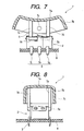
- the switch device is, as shown in Fig. 7 and Fig. 8, is provided with a tab member 7 for operating the switch device disposed above the switch device, for example, on the operating enclosure (not shown) so as to be capable of a swinging motion with respect to the switch device.
- the tab member 7 includes an upper wall portion 7a formed by a curved surface, a sidewall portion 7b surrounding four sides of the upper wall portion 7a and having a gentle inclination, a pair of through holes 7c provided at the substantially center of one of the opposing sidewall portions 7b, two operating portions 7d and 7e extending downward from a predetermined alternate portion of the inner surface of the upper wall portion 7a.
- the tab member 7 is attached to, for example, the operating enclosure, not shown, so as to be capable of a swinging motion by a pair of projections (not shown) formed on the operating enclosure inserted into a pair of through holes 7c.
- the switch device is attached to a printed wiring substrate 8 by suitable means such as soldering or the like, and the two operating portions 7d and 7e of the tab member 7 are disposed in a state of being in contact with the respective lever portions 5c of the driving members 5 of the switch device.
- the tab member 7 is constructed separately from the switch device and disposed above the switch device by suitable means.
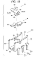
- the enclosure 1 having the case 2 and the fixed contact member 3 is placed on a predetermined assembling and transporting jig (not shown) with the upper surface of the first and the second openings 2e and 2f faced upward.
- the pair (two) of movable contact members 4 are inserted and disposed on the respective fixed contact members 3 from the first and the second openings 2e and 2f of the case 2 so as to be oriented alternately.
- the movable contact members 4 are disposed respectively in the first and the second storage sections 2g and 2h by suitable means, and the substantially centers of the respective movable contact members 4 are placed on the first fixed contact point 3a of the fixed contact member 3 so as to be capable of a seesaw movement.
- the free end of the actuating portion 5a is disposed in the vicinity of the connecting portion between the flat portion 4a and the rising portion 4b of the movable contact member 4 in an abutted state.
- the first and the second spring portions 6b and 6c of the spring member 6 are disposed so as to cover the first and the second openings 2e and 2f formed on top of the case 2, and the respective through holes 6e on the spring member 6 are engaged with the projections 2h on the case 2 in a snap-in manner, so that the spring member 6 is mounted on the case 2 (enclosure 1).
- the first and the second spring portions 6b and 6c are attached in a state of slightly pressing the tops (upper portions) of the actuating portions 5a of the respective driving members 5 resiliently toward the bottom wall 2a, and thus in a state in which the free ends (lower portions) of the actuating portions 5a forces the movable contact member 4 to be abutted against the fixed contact member 3 by such resilient pressure.
- the switch device is constructed to be assembled by storing and placing in sequence the movable contact member 4, the driving member 5, and the spring member 6 as restoring means from above into the case 2 (enclosure 1) with the fixed contact member 3 disposed therein.
- two switch element sets are such that the respective movable contact members 4 are brought into contact with the first fixed contact points 3a and the third fixed contact points 3c respectively, and the portions between the first and the third fixed contact points 3a and 3c are in the ON state, while the portions between the first fixed contact points 3a and the second fixed contact points 3b are moved away from each other and thus the portions between the first and the second fixed contact points 3a and 3b are in the OFF(non-contact) state, which is the first switched state.
- the two switch element sets disposed alternately (with back side faced to each other) in the case 2 is also in the first switched state.
- the pair of projections 5b of the other driving members 5 are adapted to move slightly upward against a resilient force of the spring member 6 in the pair of recesses 2k on the case 2.
- the pair of projections 5b of the other driving member 5 are constructed to move slightly downward by a resilient force of the spring member 6 in the pair of recesses 2j of the case 2 in this state.
- the switch device is a so-called monopolar/double-throw switch having only a set of switch element.
- An enclosure 21 is formed of insulative synthetic resin material, includes a substantially box-shaped case 22 formed by molding, and a set of fixed contact member 23 formed in the case 22 by insert molding of metallic material so as to extend partly outward from the case 22.
- the case 22 includes a rectangular bottom wall 22a, a pair of opposing sidewalls 22b extending forward from the bottom wall 22n, a pair of open-top recesses 22c formed at the upper ends of the pair of sidewalls 22b respectively, an opened space 22d defined on the upper side of the pair of sidewalls 22b, and a stopper 22e provided in the vicinity of one of the recesses 22c on the outer side surface of one of the sidewalls 22b.
- the pair of recesses 22c are disposed in such a manner that the axial line at the center thereof are coaxially aligned.
- case 22 is a monopolar/double-throw switch device having only one switch element set and has one of the sidewalls 22b and the opened space 22d
- case 2 in the first embodiment is a bipolar/double-throw switch device having two switch element sets, the first and the second sidewalls 2b and 2c surrounding four sides, and two openings 2e and 2f.
- the fixed contact member 23 has the same construction and layout as the fixed contact member 3 described in conjunction with the first embodiment described above, detailed description will not be made.
- the fixed contact member 23 is constructed only of one set, and includes a set of the first, the second, and the third terminals 23a, 23b and 23c as a part of the construction.
- a movable contact member 24 and the driving member 25 have the same construction and layout as the movable contact member 4 and the driving member 5 described in conjunction with the first embodiment described above, as in the case of the fixed contact member 23, detailed description will not be made.
- a spring member 26 as restoring means is formed by press molding of a resilient metallic plate material, and includes a spring portion 26a, a pair of sidewalls 26b extending substantially vertically downward from one of the opposing ends of the spring portion 26a, and two through holes (not shown) disposed on each sidewalls.
- the spring member 26a includes a plate-shaped holding portion 26c, and a pair of tilted portion 26d tilting from the holding portion 26c.
- the spring member 26 is disposed so that the spring portion 26a covers the opened space 22d formed on the case 22, and respective through holes (not shown) formed on the spring member 26 engage the opposing end surfaces of the respective sidewalls 22b by suitable means such as snap engagement and the like so that attachment of the spring member 26 to the case 22 is ensured.
- the difference of the action of the switch device according to the second embodiment from the action of the switch device according to the first embodiment is that the tab member 7 (See Fig. 7) on the switch device according to the first embodiment is adapted to be capable of swinging in the clockwise and the counterclockwise directions in order to activate the alternately disposed two switch element sets by the action of the switch device, while the tab member 7 on the switch device according to the second embodiment is disposed so as to be capable of swinging only in one of the clockwise and the counterclockwise directions in order to activate one switch element set.
- the switch device is a so-called monopolar/double-throw switch device having only one switch element set.
- an enclosure 31 is formed of insulative synthetic resin material, and includes a substantially box-shaped case 32 formed by molding, and a set of fixed contact member 33 formed by insert molding in the case 32 of metallic material so as to extend partly outward from the case 32.
- a pair of through holes 32c of the sidewall 32b of the case 32 constitutes, so-called the recess described above.
- the fixed contact member 33 has the same construction and layout as the fixed contact member 3 of the switch device according to the first embodiment described above, detailed description will not be made.
- a fixed contact member 33 is constructed only of a set, and includes a set of a first, a second and a third terminals 33a, 33b and 33c as a part of the construction.
- a movable contact member 34 has almost the same construction as the movable contact member 4 of the switch device according to the first embodiment described above, detailed description will not be made.
- the difference between the movable contact member 34 and the movable contact member 4 described above is that the movable contact member 34 is formed by pressing of resilient conductive metal, while the movable contact member 4 described above is formed of a hard conductive metal.
- the movable contact member 34 includes a flat portion 34a, a rising portion 34b and a contact portion 34c.
- the contact portion 34c is formed so as to be deformed and moved to be bent from the rising portion 34b by its resiliency.
- the movable contact member 34 having a resiliency constitutes restoring means for restoring the driving member 35 that will be described later to its original position.
- the movable contact member 34 is disposed in the case by suitable means so as to be capable of a seesaw movement about the first fixed contact point (not shown) in the case 32.
- the contact portion 34c of the movable contact member 34 is disposed opposingly to the second contact point 33d, and the flat portion 34a is disposed opposingly to the third fixed contact point (not shown).
- the driving member 35 is formed in almost the same construction as the driving member 5 of the switch device according to the first embodiment described above, detailed description will not be made.
- the driving member 35 includes an actuating portion 35a, a pair of projections 35b, and a lever portion 35c, and each of the respective projections 35b includes a larger diameter portion 35d and the smaller diameter portion 35e.
- the length of one of the smaller diameter portions 35e of the projections 35b is longer than the length of the other smaller diameter portion 35e, and the lever portion 35c extends from the substantially center of one of the smaller diameter portions 35e in the direction orthogonal to the axial center of the projection 35b.
- the driving member 35 is disposed in such a manner that the respective distal ends of the respective smaller diameter portions 35e of the pair of projections 35b are inserted into the pair of through holes 32c on the case 32, whereby the actuating portion 35a can rotate.
- the lever portion 35c of the driving member 35 is disposed in the vicinity of the one of the pair of the sidewalls 32b of the case 32.
- the switch device includes three members of; the enclosure 31 having the case 32 and a set of fixed contact member 33, a single piece of the movable contact member 34 and a single piece of the driving member 35.
- a switch element set is constructed of a set of fixed contact member 33, a single piece of the movable contact member 34, and a single piece of the driving member 35.
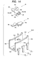
- the enclosure 31 having the case 32 and the fixed contact member 33 is placed on a predetermined assembling and transporting jib (not shown) with the opened space 32d faced upward.
- the movable contact member 34 is inserted and disposed from the opened space 32d of the case 32 on the respective fixed contact member 33 in a predetermined orientation.
- a predetermined assembling jig (not shown) for widening the initial width of the opened space 32d of the case 32 to a predetermined width is disposed on the opened space 32d, and the width of the opened space 32d is widened to a predetermined width by this assembling jib.
- the assembling jib for widening the width of the opened space 32d into the predetermined width is removed to restore the width of the opened space 32d to the original width.
- the lever portion 35c of the driving member 35 is disposed in parallel with the surface of the bottom wall 32a and disposed in the vicinity of the stopper 32e of the case 32.
- the free end of the actuating portion 35a of the driving member 35 abuts against and is disposed on the movable contact member 34.
- the lever portion 35c of the driving member 35 is in parallel with the bottom wall 32a, and as in the case of the switch device according to the first embodiment described above, the driving member 35 is placed at the neutral position.
- the switch element is in the first switched state in which the movable contact member 34 is in contact with the first fixed contact point 33a and the third fixed contact point 33c so that the portion between the first and the third fixed contact points 33a and 33c is in the ON (contact) state, and the first and the second fixed contact points 33a and 33b are moved away from each other so that the portion between the first fixed contact point 33a and the second fixed contact point 33b is in the OFF (non-contact) state.
- the driving member 35 is adapted to rotate about the axial centers of the pair of projections 35b.
- the switch device is a so-called monopolar/double-throw switch device having only one switch element set.
- the basic construction of the switch device in the fourth embodiment is the almost the same construction as the switch device of the third embodiment described above, the same construction is represented by the same reference numerals and detailed description will not be made.
- the switch device according to the fourth embodiment will be described only about the difference from the switch device according to the third embodiment.
- the pair of through holes 32c constituting the recesses are formed on the sidewalls 32b of the case 32 and the pair of projections 35b are formed on the driving member 35.
- the pair of projections 35b of the driving member 35 are disposed in the pair of through holes 32c of the case 32.
- the switch device according to the third embodiment and the switch device according to the fourth embodiment differ from each other in that the recess and the projection are disposed in the different manners.
- This switch device will be described as a monopolar/single-throw switch device having a switch element set.
- a case 51 includes a rectangular bottom wall 51a, a sidewall 51b extending from the bottom wall 51a and surrounding four sides, an opening 51c formed on top of the sidewall 51b, and a pair of holes 51d provided coaxially on one of the opposing sidewalls 51b.
- a fixed contact member 52 includes a first fixed contact point 52a, and a second fixed contact point 52b disposed away from the first fixed contact point 52a by a predetermined distance.
- the first fixed contact point 52a includes a first contact portion 52c and a first terminal 52d extending from the first contact portion 52c.
- the fixed contact member 52 constructed of the first fixed contact point 52a and the second fixed contact point 52b is insert molded on the bottom wall 51a of the case 51, and the first contact portion 52c and the second contact portion 52e are disposed so as to be exposed from the inner wall surface of the bottom wall 51a.
- the movable contact member 53 is formed of a resilient plate material of conductive metal, and includes a flat portion 53a formed on one of the end side, and a rising portion 53b extending from one of the ends of the flat portion 53a in a tilted manner, and a contact portion 53c extending from one of the ends of the rising portion 53b.
- the movable contact member 53 is formed into an asymmetric shape.
- One of the ends of the flat portion 53a is continuing from the second contact portion 52e of the second fixed contact point 52b, whereby the movable contact member 53 is integrated with the second fixed contact point 52b.
- the movable contact member 53 is disposed in the sidewall 51b surrounding four sides opposingly to the bottom wall 51a, and the contact portion 53c is disposed at the position away from (non-contact) the first contact portion 52c of the first fixed contact point 52a.
- the resilient movable contact member 53 is formed of a resilient conductive metal, for example, the contact portion 53c is formed so as to be deformed and moved to be bent from the rising portion 53b by its resiliency.
- the movable contact member 53 having a resiliency constitutes restoring means for restoring a driving member 54 that will be described later to its original position.
- the driving member 54 has almost the same construction as the driving member 34 of the switch device according to the third embodiment described above, and includes an actuating portion 54a, a pair of projections 54b and a lever portion 54c, and each of the respective projections 54b includes a larger diameter portion (not shown) and a smaller diameter portion 54d.
- the length of the smaller diameter portion 54d of one of the projections 54b is longer than the length of the other smaller diameter portion (not shown), and the lever portion 54c extends from the substantially center of one of the smaller diameter portions 54d in the direction orthogonal to the axial center of the projection 54b.
- the switch device is constructed of two members; one of the members is constructed of the case 51, the fixed contact member 52 and the movable contact member 53, and the other one of the members is constructed of the driving member 54.
- the switch device is constructed of the second fixed contact point 52b of the fixed contact member 52 and the flat portion 53a of the movable contact member 53 integrally continuing with each other as described above, the second fixed contact point 52b and the movable contact member 53 are constantly conducted (ON: contact) irrespective of whether or not the driving member 54 is not in operation or in operation.
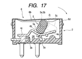
- the action of the lever portion 54c of the driving member 54 when not in operation will be described here.
- the actuating portion 54a of the driving member 54 is disposed perpendicularly with respect to the bottom wall 51a, and the free end of the actuating portion 54a is in abutment with the flat portion 53a of the movable contact member 53.
- the contact portion 53c of the movable contact member 53 is away from the first fixed contact point 52a of the fixed contact member 52, and thus the switch element is in the OFF (non-contact) state.
- the resilient rising portion 53b rotates counterclockwise about the flat portion 53a (pressed downward), and the rotation (pressed downward) of the rising portion 53b allows the contact portion 53c to be brought into contact with the first fixed contact point 52a (first contact portion 52c) of the fixed contact member 52, whereby the switch element is brought into the ON (contact) state.
- the actuating portion 54a When the operation of the tab member (not shown) is released, the actuating portion 54a is displaced from the rising portion 53b and restored to the original position by a resilient force (restoring force) of the movable contact member 53, and the contact portion 53c is moved away from the first fixed contact point 52a, whereby the switch element is brought into the original OFF (non-contact) state.
- the lever potion 54c rotates counterclockwise.
- This switch device is described as a monopolar/single-throw switch device having a switch element set.
- this switch device the same components as the switch device according to the first embodiment described above will be represented by the same reference numerals and will not be described here.
- the fixed contact member 3 includes the first, the second and the third fixed contact points 3a, 3b and 3c, and the first, the second and the third terminals 3e, 3g and 3j of the first, the second and the third fixed contact point 3a, 3b and 3c respectively in the switch device according to the first embodiment, while the fixed contact member 3 includes only the first and the second fixed contact points 3a and 3b, and the first and the second terminals 3e and 3g respectively of the first and the second fixed contact point 3a and 3b in the switch device according to the sixth embodiment.
- the switch device according to the sixth embodiment is not provided with the third fixed contact point 3c.
- the monopolar/single-throw switch device is constructed.
- switch device is described as a monopolar/single-throw switch device here, it is applicable as a matter of course to dispose two of these switch devices in parallel to form a bipolar/single-throw switch device.
- the action of the switch device according to the sixth embodiment is almost the same as the action of the bipolar/double-throw switch device in the first embodiment described above, and the difference is only that the switch device according to the sixth embodiment is a single-throw switch device as described above. Therefore, description will not be made here.
- the restoring means in the embodiments described above is formed by a plate-shaped resilient spring member, it is not limited thereto, and the restoring means may be formed of a resilient member such as rubber or of a wire spring or the like.
- the switch device includes: a case having a bottom wall and at least an opposing pair of sidewalls extending from the bottom wall; a fixed contact member provided on the bottom wall of the case; a movable contact member disposed in the case; a driving member rotatably mounted on the pair of sidewalls; restoring means for restoring the driving member to the original position; and the driving member including an actuating portion for moving the movable contact member and an operating portion for rotating the actuating member, and is constructed in such a manner that the actuating portion is rotated when the operating portion of the driving member is driven and hence the actuating portion moves the movable contact member so that the movable contact member is brought into contact with a fixed contact member, and the driving member is restored to the original position in which the movable contact member and the fixed contact member are brought out of contact by restoring means when the driven state of the operating portion is released. Accordingly, since the number of components is small, and it can be assembled by stacking the components in sequence from
- the switch device according to the invention is constructed in such a manner that the driving member is urged by the spring member toward the bottom wall, and the driving member is restored to the original state by an urging force of the spring member, the layout and the operations of the driving member and the spring member are simple, and thus the switch device which is simple in construction and hence is cost-effective may be provided.
- the switch device of the invention is constructed in such a manner that the operating portion of the driving member is positioned outside the case and the stopper is disposed outside the case, so that the operating portion abuts against the stopper to limit the rotational movement thereof, the operating portion is positioned outside the case, whereby the switch device in which the operation of the operating portion may be facilitated and thus the operation and the construction are simple is provided.
- the switch device according to the invention is constructed in such a manner that the driving member is formed with a projection, and the case is formed with a recess, and that the projection is.disposed into the recess so that the driving member is rotatably mounted to the case, it is easier to form the projection on the driving member and the recess on the case, whereby the cost-effective switch device that can easily be assembled is provided.
- the Switch device according to the invention is constructed in such a manner that the recess on the sidewall is formed to have an almost same width as the diameter of the recess on the driving member, and the projection is adapted to be movable in the vertical direction in the recess, the projection of the driving member is movable in the vertical direction in the recess, whereby the switch device in which the projection is not subject to an excessive force and a stable performance may be maintained for a long time is provided.
- the switch member according to the invention is constructed in such a manner that the movable contact member performs a seesaw movement by the pressure of the actuating portion being displaced from the flat portion to the rising portion so that the movable contact member is brought into contact with the fixed contact member, and performs a seesaw movement to be restored to the original state by the pressure of the actuating portion being displaced from the rising portion to the flat portion so that the movable contact member is brought out of contact with the fixed contact member, the seesaw movement of the movable contact member may be performed by a simple action of the. actuating portion of the driving member, whereby the switch device ensuring a reliable action is provided.
- the switch device of the invention is constructed in such a manner that the fixed contact member includes the third fixed contact point, and the movable contact member is brought into contact with the first fixed contact point and the third fixed contact point and thus the portion between the first and the third fixed contact points is in the ON state when the driving member is not in operation, while the flat portion of the movable contact member is brought out of contact with the third fixed contact point and thus the portion between the first and the third fixed contact points is in the OFF state, and simultaneously the movable contact member is bought into contact with the second fixed contact point so that the portion between the first and the second fixed contact points is in the ON state when the driving member is actuated, whereby the cost-effective monopolar/double-throw switch device including the small number of components is provided.
- the switch device according to the invention is constructed in such a manner that a switch element set is constructed of the fixed contact member, the movable contact member, the driving member, and the restoring means and two switching element sets are disposed in parallel in the case, whereby the cost-effective bipolar/double-throw switch device including small number of components and thus being easy to assemble is provided.
- the switch device according to the invention is constructed in such a manner that the two movable contact members constituting a part of two sets of switching elements are disposed alternately with respect to the case so that the flat portions of the respective movable contact members are oriented in the opposite directions. Accordingly, since the asymmetric two movable contact members are disposed alternately with respect to the case, the longitudinal dimension of the case may be shortened, whereby the downs izable switch device is provided.
Landscapes
- Tumbler Switches (AREA)
- Mechanisms For Operating Contacts (AREA)
- Contacts (AREA)
- Rotary Switch, Piano Key Switch, And Lever Switch (AREA)
- Push-Button Switches (AREA)
Abstract
Description
characterized in that the driving member is urged by the spring member toward the bottom wall, and the driving member is restored to the original state by an urging force of the spring member.
Since the action from this state on is almost the same as the series of action of one of the driving
In this state, when the switch device is a power window switch, for example, the motor is switched to the direction to close the window glass.
Claims (20)
- A switch device comprising:wherein said actuating portion is rotated when said operating portion of said driving member is driven and hence said actuating portion moves said movable contact member so that said movable contact member is brought into contact with said fixed contact member, and said driving member is restored to the original state in which said movable contact member and said fixed contact point are brought out of contact by said restoring means when the driven state of said operating portion is released.a case having a bottom wall and at least an opposing pair of sidewalls extending from the bottom wall;a fixed contact member provided on the bottom wall of the case;a movable contact member disposed in said case;a driving member rotatably mounted on said pair of sidewalls; andrestoring means for restoring said driving member to the original position, andsaid driving member including an actuating portion for moving said movable contact member and an operating portion for rotating the actuating portion,
- A switch device according to Claim 1, wherein said restoring means is constructed of a spring member.
- A switch device according to Claim 2, wherein said driving member is urged by said spring member toward said bottom wall, and said driving member is restored to the original state by an urging force of said spring member.
- A switch device according to Claim 2 or 3, wherein said spring member is formed of a plate having spring characteristics.
- A switch device according to any of claims 2 to 4, wherein said case includes a sidewall surrounding four sides and an opening formed on top thereof, and wherein the opening is covered by said spring member formed of said plate.
- A switch device according to any of claims 2 to 5, wherein said spring ember is snap engaged with said sidewall of said case.
- A switch device according to any of Claims 2 to 6, wherein said driving member moves away from said bottom wall against an urging force of said spring member when said actuating portion of said driving member rotates, and simultaneously, said driving member rotates so that said actuating portion moves said movable contact member to bring said movable contact member and said fixed contact member into contact with each other, while said driving member is restored to the original state by said spring member to bring said movable contact member out of contact with said fixed contact member when the rotation of said driving member is released.
- A switch device according to any of Claims 1 to 7, wherein said case is provided with a stopper for limiting the rotatable range of said operating portion of said driving member.
- A switch device according to Claim 8, wherein said operating portion of said driving member is positioned outside said case and said stopper is disposed outside said case, so that said operating portion abuts against said stopper to limit the rotational movement thereof.
- A switch device according to any of Claims 1 to 9, further comprising a projection on one of said driving member and one of said opposing sidewalls of said case, and a recessed portion on the other one of them and said projection in said recess, wherein said driving member is rotatably mounted on said case.
- A switch device according to Claim 10, wherein said driving member is formed with said projection, said case is formed with said recess, and said projection is disposed into said recess so that said driving member is rotatably mounted to said case.
- A switch device according to Claim 11, wherein the upper end of said sidewall includes said recess opened on top, and said projection is fitted into said recess from above.
- A switch device according to Claim 12, wherein said recess on said sidewall is formed to have almost the same width as the diameter of said projection on said driving member, and said projection is adapted to be movable in the vertical direction in said recess.
- A switch device according to any of Claims 1 to 13, wherein said movable contact member includes a flat portion, a rising portion extending from one of the ends of the flat portion in a tilted state, and a contact portion extending from one of the ends of the rising portion and coming into and out of contact with said fixed contact member, and said movable contact member is supported so as to be capable of a seesaw movement.
- A switch member according to Claim 14, wherein said movable contact member performs a seesaw movement by the pressure of said actuating portion being displaced from said flat portion to said rising portion so that said movable contact member is brought into contact with said fixed contact member, and performs a seesaw movement to be restored to the original state by the pressure of said actuating portion being displaced from said rising portion to said flat portion so that said movable contact member is brought out of contact with said fixed contact member.
- A switch member according to Claim 14 or 15, wherein said fixed contact member is constantly in contact with said movable contact point, and includes a first fixed contact point for supporting said movable contact member, and a second fixed contact point for coming into and out of contact with said movable contact member, and wherein said movable contact member is adapted to perform a seesaw movement about said first fixed contact point.
- A switch device according to Claim 16, wherein said fixed contact member includes a third fixed contact point, and said movable contact member is brought into contact with said first fixed contact point and said third fixed contact point and thus the portion between said first and said third fixed contact points is in the ON state when said driving member is not in operation, while said flat portion of said movable contact member is brought out of contact with said third fixed contact point and thus the portion between said first and said third fixed contact points is in the OFF state, and simultaneously said movable contact member is bought into contact with said second fixed contact point so that the portion. between said first and said second fixed contact points is in the ON state when said driving member is actuated.
- A switch device according to any of Claims 1 to 17, wherein a switch element set is constructed of said fixed contact member, said movable contact member, said driving member, and said restoring means, and two switching element sets are disposed in parallel in the case.
- A switch device according to Claim 18, wherein said two movable contact members constituting a part of said two switching element sets are disposed alternately with respect to said case so that said flat portions of said respective movable contact members are oriented in the opposite directions.
- A switching device according to Claim 18 or 19, further comprising said spring member formed of a plate, wherein said spring member includes a slit and a first and a second spring portions located at both sides of the slit, wherein the first and the second spring portions are disposed so as to cover the upper portion of said case, and wherein one of said driving member constituting a part of said two switching elements is pressurized by said first spring portion and said other driving member is pressurized by said second spring portion.
Applications Claiming Priority (2)
| Application Number | Priority Date | Filing Date | Title |
|---|---|---|---|
| JP2002053854 | 2002-02-28 | ||
| JP2002053854A JP4121754B2 (en) | 2002-02-28 | 2002-02-28 | Switch device |
Publications (3)
| Publication Number | Publication Date |
|---|---|
| EP1341200A2 true EP1341200A2 (en) | 2003-09-03 |
| EP1341200A3 EP1341200A3 (en) | 2003-09-10 |
| EP1341200B1 EP1341200B1 (en) | 2006-04-26 |
Family
ID=27678558
Family Applications (1)
| Application Number | Title | Priority Date | Filing Date |
|---|---|---|---|
| EP03004274A Expired - Lifetime EP1341200B1 (en) | 2002-02-28 | 2003-02-26 | Switch device |
Country Status (5)
| Country | Link |
|---|---|
| US (1) | US6841750B2 (en) |
| EP (1) | EP1341200B1 (en) |
| JP (1) | JP4121754B2 (en) |
| KR (1) | KR100519195B1 (en) |
| DE (1) | DE60304758T2 (en) |
Cited By (2)
| Publication number | Priority date | Publication date | Assignee | Title |
|---|---|---|---|---|
| FR2886757A1 (en) * | 2005-06-07 | 2006-12-08 | Legrand France | Electrically controlled shutter/curtain control device, has control lever with support zone supporting on shift lever having support zone supporting on tilting unit, so that control lever has angular displacement lower than tilting of unit |
| CN109478477A (en) * | 2016-07-05 | 2019-03-15 | Zf 腓德烈斯哈芬股份公司 | Operating components for motor vehicles |
Families Citing this family (13)
| Publication number | Priority date | Publication date | Assignee | Title |
|---|---|---|---|---|
| KR100475488B1 (en) * | 2002-04-15 | 2005-03-10 | 강선우 | Sealed switch and producing the same |
| JP4279648B2 (en) * | 2003-10-20 | 2009-06-17 | アルプス電気株式会社 | Switch device |
| JP2005158492A (en) * | 2003-11-26 | 2005-06-16 | Tokai Rika Co Ltd | Power window switch device |
| JP4792350B2 (en) * | 2006-08-10 | 2011-10-12 | 東洋電装株式会社 | switch |
| JP4717747B2 (en) * | 2006-08-10 | 2011-07-06 | 東洋電装株式会社 | Automatic reset switch |
| JP2012142229A (en) | 2011-01-05 | 2012-07-26 | Yazaki Corp | Switch device |
| CN103198937B (en) * | 2013-03-08 | 2015-10-28 | 上海拜骋电器有限公司 | The interlock compound brake structure of switch, switch and electric tool |
| JP5805139B2 (en) * | 2013-05-24 | 2015-11-04 | アルプス電気株式会社 | Switching device |
| SG2013094115A (en) * | 2013-12-19 | 2015-07-30 | Schneider Electric South East Asia Hq Pte Ltd | Trigger actuator for a switching device |
| JP2016031847A (en) * | 2014-07-29 | 2016-03-07 | 株式会社東海理化電機製作所 | Switching device |
| JP5913700B1 (en) * | 2015-07-30 | 2016-04-27 | ミック電子工業株式会社 | Double seesaw switch |
| US10479166B2 (en) * | 2017-12-29 | 2019-11-19 | Denso International America, Inc. | Toggle button |
| CN113314365B (en) * | 2021-05-27 | 2024-02-27 | 宁波力隆机电股份有限公司 | Switch device with good sealing performance |
Family Cites Families (9)
| Publication number | Priority date | Publication date | Assignee | Title |
|---|---|---|---|---|
| US3299224A (en) * | 1966-01-07 | 1967-01-17 | Boyne Products Inc | Self-centering toggle switch with improved actuator contact structure |
| IT1144854B (en) * | 1981-05-29 | 1986-10-29 | Fiat Auto Spa | UNSTABLE SWITCH DEVICE FOR WIPER WIPER INTEGRATED IN THE DEVIATOR FOR VEHICLES |
| JP2525658Y2 (en) * | 1991-09-18 | 1997-02-12 | アルプス電気株式会社 | Seesaw switch |
| US5967303A (en) * | 1998-10-30 | 1999-10-19 | Leviton Manufacturing Co., Inc. | Switch activating mechanism |
| US6140713A (en) * | 1999-03-02 | 2000-10-31 | Methode Electronics, Inc. | Electrical cammed switch |
| JP2000276975A (en) * | 1999-03-23 | 2000-10-06 | Mikku Enterprise:Kk | Microswitch |
| US6420669B1 (en) * | 1999-05-10 | 2002-07-16 | Leviton Manufacturing Co., Inc. | Toggle mechanism for toggle switches |
| US6130393A (en) * | 1999-06-24 | 2000-10-10 | Defond Manufacturing Ltd. | Electrical rocker switch |
| US6040543A (en) * | 1999-08-13 | 2000-03-21 | Egs Electrical Group Llc | Explosion proof toggle switch |
-
2002
- 2002-02-28 JP JP2002053854A patent/JP4121754B2/en not_active Expired - Fee Related
-
2003
- 2003-02-26 EP EP03004274A patent/EP1341200B1/en not_active Expired - Lifetime
- 2003-02-26 DE DE60304758T patent/DE60304758T2/en not_active Expired - Lifetime
- 2003-02-27 US US10/376,613 patent/US6841750B2/en not_active Expired - Lifetime
- 2003-02-27 KR KR10-2003-0012282A patent/KR100519195B1/en not_active Expired - Fee Related
Cited By (4)
| Publication number | Priority date | Publication date | Assignee | Title |
|---|---|---|---|---|
| FR2886757A1 (en) * | 2005-06-07 | 2006-12-08 | Legrand France | Electrically controlled shutter/curtain control device, has control lever with support zone supporting on shift lever having support zone supporting on tilting unit, so that control lever has angular displacement lower than tilting of unit |
| EP1732096A1 (en) * | 2005-06-07 | 2006-12-13 | Legrand France | Rocking lever control device with reduced angular displacement |
| CN1877482B (en) * | 2005-06-07 | 2013-07-31 | 勒格朗法国公司 | Tilting lever type control device with reduced angle motion |
| CN109478477A (en) * | 2016-07-05 | 2019-03-15 | Zf 腓德烈斯哈芬股份公司 | Operating components for motor vehicles |
Also Published As
| Publication number | Publication date |
|---|---|
| EP1341200B1 (en) | 2006-04-26 |
| KR100519195B1 (en) | 2005-10-06 |
| EP1341200A3 (en) | 2003-09-10 |
| KR20030071554A (en) | 2003-09-03 |
| DE60304758D1 (en) | 2006-06-01 |
| JP2003257270A (en) | 2003-09-12 |
| DE60304758T2 (en) | 2007-04-26 |
| US20030159912A1 (en) | 2003-08-28 |
| US6841750B2 (en) | 2005-01-11 |
| JP4121754B2 (en) | 2008-07-23 |
Similar Documents
| Publication | Publication Date | Title |
|---|---|---|
| EP1341200B1 (en) | Switch device | |
| US6211474B1 (en) | Multi-input switch | |
| US6348664B2 (en) | Multidirectional switch whose stem can be tilted and pushed | |
| US6903293B2 (en) | Switch device having good sense of operational touch even when sliding operating knob or rocking operating knob is attached thereto | |
| CN100437866C (en) | Composite switchgear | |
| WO2019187343A1 (en) | Switch device | |
| EP1760742A2 (en) | Switch device and steering switch apparatus equipped with the switch device | |
| EP1873799B1 (en) | Switch | |
| KR19980023941A (en) | Complex operation type electric parts | |
| US20050067263A1 (en) | Switch device | |
| US7115826B2 (en) | Switch device capable of being small-sized and preventing introduction of extraneous material thereinto | |
| KR20020061492A (en) | Switch device | |
| JP2003331690A (en) | Switch device | |
| JP2003016873A (en) | Switch device | |
| JP2007207015A (en) | Multi-directional input device | |
| KR100298507B1 (en) | switch | |
| JP3790384B2 (en) | Multi-directional switch | |
| JP3937670B2 (en) | Multi-directional operation switch | |
| JP3569079B2 (en) | switch | |
| JP3858303B2 (en) | Automatic reset slide switch | |
| JP2003272482A (en) | Switch | |
| JP4326987B2 (en) | Switch device | |
| JP3819677B2 (en) | Input device | |
| JP4087626B2 (en) | Lever type switch | |
| CN100458993C (en) | Switch contact structure |
Legal Events
| Date | Code | Title | Description |
|---|---|---|---|
| PUAI | Public reference made under article 153(3) epc to a published international application that has entered the european phase |
Free format text: ORIGINAL CODE: 0009012 |
|
| PUAL | Search report despatched |
Free format text: ORIGINAL CODE: 0009013 |
|
| AK | Designated contracting states |
Kind code of ref document: A2 Designated state(s): AT BE BG CH CY CZ DE DK EE ES FI FR GB GR HU IE IT LI LU MC NL PT SE SI SK TR |
|
| AX | Request for extension of the european patent |
Extension state: AL LT LV MK RO |
|
| AK | Designated contracting states |
Kind code of ref document: A3 Designated state(s): AT BE BG CH CY CZ DE DK EE ES FI FR GB GR HU IE IT LI LU MC NL PT SE SI SK TR |
|
| AX | Request for extension of the european patent |
Extension state: AL LT LV MK RO |
|
| 17P | Request for examination filed |
Effective date: 20040209 |
|
| AKX | Designation fees paid |
Designated state(s): DE FR GB |
|
| 17Q | First examination report despatched |
Effective date: 20040428 |
|
| GRAP | Despatch of communication of intention to grant a patent |
Free format text: ORIGINAL CODE: EPIDOSNIGR1 |
|
| GRAS | Grant fee paid |
Free format text: ORIGINAL CODE: EPIDOSNIGR3 |
|
| GRAA | (expected) grant |
Free format text: ORIGINAL CODE: 0009210 |
|
| AK | Designated contracting states |
Kind code of ref document: B1 Designated state(s): DE FR GB |
|
| REG | Reference to a national code |
Ref country code: GB Ref legal event code: FG4D |
|
| REF | Corresponds to: |
Ref document number: 60304758 Country of ref document: DE Date of ref document: 20060601 Kind code of ref document: P |
|
| ET | Fr: translation filed | ||
| PLBE | No opposition filed within time limit |
Free format text: ORIGINAL CODE: 0009261 |
|
| STAA | Information on the status of an ep patent application or granted ep patent |
Free format text: STATUS: NO OPPOSITION FILED WITHIN TIME LIMIT |
|
| 26N | No opposition filed |
Effective date: 20070129 |
|
| REG | Reference to a national code |
Ref country code: FR Ref legal event code: PLFP Year of fee payment: 14 |
|
| REG | Reference to a national code |
Ref country code: FR Ref legal event code: PLFP Year of fee payment: 15 |
|
| REG | Reference to a national code |
Ref country code: DE Ref legal event code: R082 Ref document number: 60304758 Country of ref document: DE Representative=s name: SCHMITT-NILSON SCHRAUD WAIBEL WOHLFROM PATENTA, DE |
|
| REG | Reference to a national code |
Ref country code: FR Ref legal event code: PLFP Year of fee payment: 16 |
|
| REG | Reference to a national code |
Ref country code: DE Ref legal event code: R082 Ref document number: 60304758 Country of ref document: DE Representative=s name: SCHMITT-NILSON SCHRAUD WAIBEL WOHLFROM PATENTA, DE Ref country code: DE Ref legal event code: R081 Ref document number: 60304758 Country of ref document: DE Owner name: ALPS ALPINE CO., LTD., JP Free format text: FORMER OWNER: ALPS ELECTRIC CO., LTD., TOKIO/TOKYO, JP |
|
| PGFP | Annual fee paid to national office [announced via postgrant information from national office to epo] |
Ref country code: DE Payment date: 20200219 Year of fee payment: 18 Ref country code: GB Payment date: 20200219 Year of fee payment: 18 |
|
| PGFP | Annual fee paid to national office [announced via postgrant information from national office to epo] |
Ref country code: FR Payment date: 20200219 Year of fee payment: 18 |
|
| REG | Reference to a national code |
Ref country code: DE Ref legal event code: R119 Ref document number: 60304758 Country of ref document: DE |
|
| GBPC | Gb: european patent ceased through non-payment of renewal fee |
Effective date: 20210226 |
|
| PG25 | Lapsed in a contracting state [announced via postgrant information from national office to epo] |
Ref country code: DE Free format text: LAPSE BECAUSE OF NON-PAYMENT OF DUE FEES Effective date: 20210901 Ref country code: FR Free format text: LAPSE BECAUSE OF NON-PAYMENT OF DUE FEES Effective date: 20210228 Ref country code: GB Free format text: LAPSE BECAUSE OF NON-PAYMENT OF DUE FEES Effective date: 20210226 |